Yafang Hou,
Yuan Deng*,
Yao Wang and
HongLi Gao
Beijing Key Laboratory of Special Functional Materials and Films, School of Materials Science & Engineering, Beihang University, Beijing, 100191, China. E-mail: dengyuan@buaa.edu.cn
First published on 17th August 2015
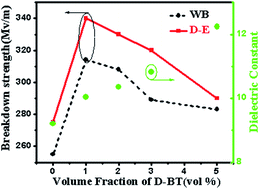
BaTiO3/poly(vinylidene fluoride) (BT/PVDF) composite material, a promising dielectric material for capacitor, has recently attracted much attention because of the promising dielectric performance and its abundant availability. Insufficient control of the hierarchal morphology of the blend has yielded a precipitous decline in breakdown strength at high BT nanoparticles volume fractions. Here, we demonstrate that breakdown strength and energy storage density can be increased up to higher value by creating uniform distribution of low content of BT nanoparticles in PVDF matrix. The dielectric properties of BT/PVDF nanocomposite were measured as a function of BT nanoparticles loading. The nanocomposite displayed a 150% increase in dielectric breakdown strength and energy density increased to more than triple that of the pure PVDF even at the 1 vol% BT nanoparticles loading. It was attributed to the uniform distribution of low content BT nanoparticles in PVDF matrix, which lead to superior dielectric breakdown strength and energy storage density than those of composites filled with high content of BT nanoparticles. Furthermore, the nanocomposites films with low content of fillers were more flexible and cost-effective. The finding based on this research provides a low-cost method to achieve high performance in capacitor.
Dielectric polymer, while routinely exhibiting breakdown strength of >200 MV m−1, are limited in storage energy density by the low dielectric constant (∼2–3).3 The energy storage density of the best commercial capacitor film represented by biaxially oriented polypropylenes (BOPP) is only about 1.2 J cm−1.3,4 Polymer–inorganic composites are being considered as potential materials for capacitive energy storage systems requiring high breakdown strength, large energy storage density, low dielectric loss, and fast charge–discharge capability.5,6 In particular, the underlying motivation behind using these hybrid composites is that the potential combination of increased breakdown strength and dielectric constant. However, by traditional methods (e.g., melt blending or solution mixing), the realization of high enough dielectric constant in composites needs a high loading of ceramic filler (i.e., >50 vol%)7,8 which inevitably raises the issues of inhomogeneity and aggregation filler in the polymer matrices, resulting in deteriorated mechanical properties, high dielectric loss, and low breakdown strength. At the same time, the non-uniform dispersion caused by high concentration of ceramic fillers would result in dropped dielectric constant with further increase of particles to higher loading.9–11
Recently, several strategies for nanocomposites with high dielectric constant, low dielectric loss and maintained or improved breakdown strength has been developed, such as grafting the end-functionalized polymer chains onto nanoparticles surfaces,12–14 modifying the nanoparticles as core–shell structure,10,15,16 and in situ polymerization of monomer onto nanoparticles surfaces.17,18 The purpose of these methods is to improve the dispersion of the high content of nanoparticles, further improve the dielectric constant while maintaining certain breakdown strength and the energy storage density of the composites. For instance, the work of Perry et al. reported that the poly(vinylidene fluoride-co-hexafluoropropylene) nanocomposites filled with phosphonic acid modified BaTiO3 exhibit an increase of dielectric constant and decrease of breakdown strength resulting in an extractable energy density of 3.2 J cm−3 at 164 MV m−1 with a nanoparticle volume fraction of 50%.8 Zhu et al.19 used surface-initiated reversible-addition-fragmentation chain transfer (RAFT) polymerization onto BaTiO3 nanoparticles surfaces and noted an improved dielectric constant for nanocomposites with PVDF resulting in an energy density of 2.5 J cm−3 with a nanoparticles volume fraction of 20%. No matter the polymer is filled with treated fillers or untreated fillers, the breakdown strength relative to the neat polymer still decreased beginning with only 5 vol% fillers loading leading to an energy density ∼5 J cm−3 even a nanoparticles volume fraction higher to 50%. The improvement of energy density in nanocomposites is limited. The flexibility of nanocomposite is poor when the content of nanoparticles is higher. To maintain high breakdown strength and consequently a high energy storage density of capacitor, the nanocomposites are prepared at a low volume fraction of nanofillers. The addition of low content of nanofillers into polymer matrices provides a means to enhance the dielectric properties beyond that of the matrix material.20–22 Fillery20 found the addition of a small amount of MMT results in a gradual increase in breakdown strength. Beier23 first reported an enhancement in breakdown strength from Ba0.7Sr0.3TiO3 (BST) nanoparticles in 1,3-bis(4-aminophenoxy) benzene (BAPB) and pyromellitic dianhydride (PMDA), and the energy density represented an increase of 107% compared with pure polyimide. These reports highlight a possible way to enhance dielectric breakdown strength and energy storage properties.
In this paper, flexible polymer composite films were prepared by a casting process with PVDF as the polymer matrix and modified BT as fillers. Song et al.7,24,25 did some researches and found that dopamine-modified fillers have significant effect on dielectric properties and energy density of polymer composites. We did a further study on the modification effect of dopamine on phase composition, breakdown strength, and energy storage density. Based on the modification effect we also investigated the role of nanoparticles in the PVDF films through microstructure observation, phase analysis, dielectric properties, and energy storage properties analytical. When the content of fillers was low, uniform distribution of BT nanoparticles in PVDF matrix could lead to superior dielectric breakdown strength and energy storage density than that of composites filled with high content of BT nanoparticles. At the same time, this method not only makes the dielectric nanocomposites film more flexible but also saves cost.
![]() | ||
Fig. 2 (a) The thermogravimetric analysis (TGA) measurements and (b) FTIR spectra of BT and D-BT nanoparticles. |
The FTIR was used to check whether the dopamine was bonded with BT nanoparticles. Fig. 2b shows the FTIR spectra of the BT nanoparticles and D-BT nanoparticles. The peaks at 1480 cm−1 and 1270 cm−1 of D-BT can be assigned to aromatic C–C stretching vibrations and aromatic amine C–N stretching vibrations, respectively, which confirms the existence of aromatic and amido groups from dopamine on D-BT nanoparticles. The appearance of 1425 cm−1 peak from BT nanoparticles represents O–H in-plane deformation vibration from water molecules or the CO band stretching vibration from CO32−. O–H stretching vibration peaks locate at the 3600–3100 cm−1 range, which were observed from both BT and D-BT nanoparticles. XPS spectra of BT nanoparticles before and after dopamine modification were employed to give further information on the interaction between dopamine and BT nanoparticles as shown in Fig. 3. The intensities of XPS signals from BT nanoparticles, i.e., Ba 4p and Ti 2p electrons were greatly reduced after dopamine was modified on their surface as shown in Fig. 3a and b. Since XPS is a surface sensitive characterization method, a thin dopamine layer outside the BT nanoparticle would largely reduce the photoelectron yield. Seen from Fig. 3c, the O atom bonding state has changed from O–H bond to C–O bond after dopamine modification, which indicates surface modification by dopamine has produced chemical bonding (BT)–O–C. Photoelectron signal from N 1s electron appeared after dopamine modification as shown in Fig. 3d. Together with the FTIR spectra the results prove that dopamine is chemically bonded with BT nanoparticles forming robust interface.7,24 The calculated weight loss is 0.52% of the D-BT nanoparticles from thermogravimetric analysis. All the discussions indicate that the dopamine hydrochloride has been successfully coated on BT nanoparticles.
![]() | ||
Fig. 3 The XPS spectra of (a) Ba 3d3 and 3d5, (b) Ti 2p1/2 and 2p2/3, (c) O 1s, and N 1s electrons before and after the surface modification by dopamine. |
Fig. 4a and b showed the cross-section SEM images of pure PVDF film and the surface SEM imagers of pure PVDF film respectively. It revealed a striking feature in the microstructure of the pure PVDF films: due to the evaporation of the solvent during film formation process, pores were formed on the surface of the PVDF film. Fig. 4c–n showed the cross-section SEM images of D-BT/PVDF nanocomposites film and the surface SEM imagers of D-BT/PVDF nanocomposites film respectively. The cross-section SEM images of D-BT/PVDF nanocomposites had the same characteristics: the interface between the fillers and the matrix was well-connected and obscured. In addition, the BT nanoparticles were surrounded by the PVDF matrix, without formation of a continuous network. Fig. 4 c, e, g and m showed the surface SEM images of 1 vol% D-BT/PVDF nanocomposites, the 2 vol% D-BT/PVDF nanocomposite, the 3 vol% D-BT/PVDF nanocomposite and the 5 vol% D-BT/PVDF nanocomposite. Compared with the pure PVDF film, the D-BT/PVDF nanocomposites hardly show any holes on the surface of films and the film surface is relativity smooth. Fig. 4o and p display the surface and cross-section SEM images of 5 vol% BT/PVDF composite. As seen, the unmodified fillers and the matrix (Fig. 4o and p) are loosely bonded while the modified fillers and the matrix (Fig. 4m and n) are compactly bonded. The D-BT particles are well distributed in the PVDF polymer matrix and show little agglomeration, while agglomeration is observed in the BT/PVDF composites as shown in Fig. 4o and p. Moreover, the BT/PVDF films exhibit defects such as voids in the composites. These results indicate that interface modification between the fillers and the matrix can diminish the defects of the composites as well as minimize the haziness of the interface between the fillers and the matrix. Nan26 reported that the heat treated could eliminate the pores and voids in the composites films. While in this paper we found by a simple method that the addition of less loading of BT nanoparticles could not only improve the dielectric properties but also eliminate the pores and voids in the PVDF film. Addition of low content of D-BT nanoparticles can fill the pores, meanwhile, the low content of ceramic nanoparticles act as nucleating agents for the PVDF crystals. So no void was observed in the surface of the composite with low content of D-BT nanoparticles. At high filler loadings, aggregation of nanoparticles leads to nonuniform distribution of the fillers and introduces large voids between fillers and PVDF, so voids were observed in composites with large content of D-BT. The addition of more BT nanoparticles reduce the surface flatness of the nanocomposites film and resulted in some voids in the nanocomposites films. Those results were closely related with the dielectric properties of the nanocomposite films. The nanocomposites in Fig. 4q show excellent flexibility which is beneficial for fabricating and shaping applications.
PVDF is a ferroelectric polymer, which has a complex structure and exhibits five crystalline phases, in which α, β, and γ are the most possible phases.27 The β-phase is technically important because it has the largest dipolar moment, not only resulting in high dielectric constant but also leading to high electroactivity.28 The β-phase can be obtained by mechanical stretching of the α-phase,29 induced by highly polar solvents, and by the addition of nucleating fillers such as BaTiO3 (ref. 30) and clay.31 Therefore, it is of important to investigate the influences of the incorporation of the ceramic nanoparticles in the polymer matrix, the XRD spectra were measured as shown in Fig. 5. The β-phase presents a better defining peak at 2θ = 20.26° relative to the sum of the diffraction at (110) and (200) planes 15, 16. In the same region, α-phase presents more characteristic peaks at 2θ = 18.30° and 2θ = 19.9° relative to diffractions in planes, (020) and (110) respectively. In addition, α-phase also presents a peak at 2θ = 26.56° corresponding to the (021) diffraction plane. The XRD pattern of pure PVDF showed peaks at 2θ values of 17.66°, 18.30° and 26.56° corresponding to α-phase. After the D-BT nanoparticles doping, the diffraction peaks of the polymer matrix got flat. The increase in intensity and gradual broadening of the diffraction peaks in the PVDF polymer matrix indicate that the crystalline size and crystallinity of the PVDF polymer could be influenced by the incorporation of the ceramic fillers. Upon the addition of the D-BT fillers, the peak at 2θ = 19.90° began to change its position to higher degree, tend to the peak of β-phase at 2θ = 20.26°. This phenomenon illustrated the addition of D-BT fillers could induce the generation of β-phase.
In order to confirm the phase shift of the films, the FTIR spectra of the films were presented in Fig. 6. The FTIR spectra of PVDF film demonstrated that there were a lot of large absorption peaks (766, and 976 cm−1) and a few small absorption peaks (840 cm−1 representing the β-phase) which revealed the main crystal phase is α-phase. In BT/PVDF nanocomposites, all peaks associated with α-phase were found to be significantly reduced with concurrent increased in the β-phase.
![]() | ||
Fig. 6 FTIR spectra of pure PVDF and D-BT/PVDF nanocomposite films with different D-BT nanoparticles loading. (1 vol% D-BT/PVDF, 2 vol% D-BT/PVDF, 3 vol% D-BT/PVDF, and 5 vol% D-BT/PVDF). |
We calculated the fraction of the β-phase (Fβ) of pure PVDF and BT/PVDF nanocomposite films from infrared spectra using Lambert–Beer law which is,
![]() | (1) |
Sample | PVDF | 1% | 2% | 3% | 5% |
---|---|---|---|---|---|
Fβ (%) | 54.08 | 77.11 | 75.68 | 78.36 | 76.99 |
We summarized the interface modification process by dopamine, which acts as a bridge between PVDF matrix and BT fillers in Fig. 7. First, hydroxyl and amine of dopamine reacted with BT nanoparticles through van der Waal forces, which produced cladded BT nanoparticles as product. Then dopamine reacted with itself by means of cross-linking reaction to form polydopamine with high adhesion, to which PVDF polymer gets strongly adhered. Therefore, the tight adhesion to the PVDF results in alignment of polymer chains forming crystals so that an all-trans planar zigzag (β-phase) pattern is induced. The large polarization resulting from the cooperation of large ferroelectric β-phase domains could improve the dielectric constant of composite. The modification of two-phase interface facilities the homogenous distribution of the BT particles in the polymer matrix, introduces more interfaces and eliminates the incompatibility.
To understand the trend in breakdown strength of the nanocomposites, firstly the high BT nanoparticles content films should be considered. The decrease of breakdown strength of nanocomposites was mainly caused by the large electrical mismatch between the matrix and fillers. Next, consider the characteristic breakdown trend from the pure polymer, the addition of a small amount of BT nanoparticles resulted in a gradual increase in breakdown strength. Nanocomposites are known to possess a high interfacial area because of the high surface area of nanoparticles fillers relative to larger fillers, in turn; the interface between the nanoparticles and polymer will be dominant even at low volume fractions. In this study, self-polymerization and composite technology based on dopamine biomimetic adhesive were developed to improve the interface effect of BT/PVDF nanocomposites. The interface modification resulted in a more homogeneous distribution of the local electric field thus apparently enhanced the breakdown strength. In the composites, dopamine acted not only as a bridge between organic and inorganic phase, but also as a passivation layer. This short-range layer surrounding the nanoparticle fillers is thought to allow charge dissipation and improve the internal electric field distribution, which helps to suppress significant interfacial polarization that exists in the case of larger fillers.23 Meanwhile, the dispersed nanoparticle fillers will limit the mobility of charger carrier, inhibit the currents passing; reinforce the breakdown strength of film. All these factors contribute increase the dielectric breakdown strength.
PVDF is an excellent ferroelectric polymer, the composites of which show good ferroelectric properties. The electric displacement–electric field (D–E) loops for PVDF-based composites with different amount of BT nanoparticles were measured at frequency of 10 Hz. The D–E curves of D-BT/PVDF composites were presented in Fig. 9. The maximum polarization and remnant polarization of D-BT/PVDF composites loaded with various concentrations of fillers are shown in the inset. Due to the difference between the Pressure tester and the Premier II ferroelectric test system, the composites films were measured at the electric field (E) over the dielectric breakdown strength field. Obviously, the shape of the hysteresis loop changes with the introduction of the BT nanoparticles. Under the electric field of 275 MV m−1, the saturated polarization of pure PVDF was ∼2.3 μC cm−2 the saturated polarization of nanocomposites consisting of modified BT nanoparticles (1%, 2%, 3%, and 5% volume fraction) lied in the range of 7–12 μC cm−2 and reached a maximum value of 12.3 μC cm−2 for composites of 1 vol% BT nanoparticles under the electric field between 290 MV m−1 and 340 MV m−1. The remnant polarization is the D value in the hysteresis loop at E = 0. Because the charge cannot be fully discharged so the high remnant polarization will decrease the discharge efficiency of the capacitor. The remnant polarization of pure PVDF was ∼1.1 μC cm−2 the remnant polarization of nanocomposites consisting of modified BT nanoparticles (1%, 2%, 3%, and 5% volume fraction) lied in the range of 4–8 μC cm−2 and reached a maximum value of 7.5 μC cm−2 for composites of 1 vol% BT nanoparticles under the electric field between 290 MV m−1 and 340 MV m−1. Nan's work26 demonstrated that the electric displacements of the nanocomposites consisting of unmodified BT nanoparticles (1%, 3%, and 5% volume fraction) and PVDF lied in the range of 5–8 μC cm−2 under 500 MV m−1. Even at 600 MV m−1, the polarizations of the nanocomposites are still under 10 μC cm−2 It was attributed to the fact that dielectric constant of the BT nanoparticles was larger than that of PVDF. Moreover, the interface areas in the composites would lead to interfacial polarization, which result in an interaction zone and significantly enhance the polarization of the composites. From FITR spectrum, the D-BT nanoparticle fillers would induce more β-phase in the nanocomposites film. The film prepared by Nan' work was nonpolar γ-phase.26 The γ-phase could improve breakdown strength and the absence of early polarization saturation.34 The unite cell of β-phase has a macroscopic dipole moment rendering it ferroelectric.35 The ferroelectric is not only resulting in high dielectric constant and leading to high electroactivity but also leading to big dielectric loss. The films were plagued by the large polarization hysteresis resulting from the cooperative polarization of large ferroelectric β-phase domains. At the same time, BT nanoparticles is ferroelectric material which polarization is mainly spontaneous polarization, so the loss of ferroelectrics occurs mostly from steering ferroelectric domain external electric field generated by the spontaneous polarization, the loss of the ferroelectric is much larger than the average electrolyte, since the BT/PVDF nanocomposites dielectric loss is mainly from the BT particles contribution. The polarization hysteresis leads to significant ferroelectric loss and greatly increased the remnant polarization of the nanocomposites. That why our films had higher saturated polarization and bigger remnant polarization than that of the literature reported even at the lower electric filed.
![]() | ||
Fig. 9 D–E curves of D-BT/PVDF composites. The maximum polarization and remnant polarization of D-BT/PVDF composites loaded with various concentrations fillers are shown in the inset. |
The energy density of the linear dielectrics can be simply expressed as . Actually, the energy density is not only related to the dielectric constant and the dielectric breakdown strength, but is also related to the polarization and the applied electric field. For the ferroelectrics, the energy density of the materials can be calculated from the D–E loops using the integral ∪ = ∫EdD. The discharged energy density and stored energy density of D-BT/PVDF composites loaded with various concentrations of D-BT nanoparticles as function of the electric field calculated from D–E loops were shown in Fig. 10. Because the polarization and breakdown strength of the D-BT/PVDF composites were greatly enhanced, the stored and discharged energy densities were both improved. The stored and discharged energy densities of nanocomposites consisting of modified BT nanoparticles (1%, 2%, 3%, and 5% volume fraction) lied in the range of 19–32 J cm−3 and 5–7 J cm−3 respectively, then reached a maximum value of 32.2 J cm−3 and 6.4 J cm−3 for composites of 1 vol% D-BT nanoparticles, which was more than three times as compared with pure PVDF.
![]() | ||
Fig. 10 The discharged energy density and stored energy density of D-BT/PVDF composites loaded with various concentrations fillers. |
As a result of the concurrent increase in breakdown strength and electric displacement, a high discharged energy density of ∼6.37 J cm−3 and stored energy density of ∼32.18 J cm−3 was achieved at 340 MV m−1 in the D-BT/PVDF nanocomposite filled with 1 vol% of BT nanoparticles, as shown in Fig. 11. The discharged energy density was 3.04 J cm−3 and stored energy density was 7.69 J cm−3 of BT/PVDF nanocomposite under a field of 275 MV m−1. For comparison, the discharged energy density of pure PVDF was 1.46 J cm−3 achieved at 275 MV m−1.
This journal is © The Royal Society of Chemistry 2015 |