Fabrication of porous g-C3N4/Ag/Fe2O3 composites with enhanced visible light photocatalysis performance

Jinjuan Xue ab, Shuaishuai Maab, Yuming Zhou*ab, Zewu Zhangab and Xiangyu Liuc
aSchool of Chemistry and Chemical Engineering, Southeast University, Nanjing 211189, P. R. China. E-mail: ymzhou@seu.edu.cn; Fax: +86 25 52090617; Tel: +86 25 52090617
bJiangsu Optoelectronic Functional Materials and Engineering Laboratory, Nanjing 211189, P. R. China
cHangzhou Silan Integrated Circuit Co., Ltd, Hangzhou 310018, P. R. China

Received 27th May 2015 , Accepted 30th June 2015

First published on 1st July 2015


Abstract

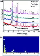
Porous graphitic carbon nitride (pg-C3N4) synthetized by pyrolysis of urea was hybridized with Ag-doped Fe2O3 to form a visible-light-driven photocatalyst pg-C3N4/Ag/Fe2O3 via a simple chemical adsorption method. The obtained pg-C3N4/Ag/Fe2O3 composites with different Ag/Fe2O3 content were characterized in terms of composition, morphology, and optical properties by XRD, EDS, FT-IR, TEM and UV-vis DRS. The photocatalytic activities were evaluated by degradation of Rhodamine B (RhB) as a representative organic pollutant under visible light irradiation. The results showed Ag/Fe2O3 (5 wt%) modified pg-C3N4 exhibited excellent photocatalytic activity in the degradation of RhB and the degradation rate was 2.74 times higher than that of pure pg-C3N4. The heterostructured coupling of pg-C3N4 with a novel metal, Ag, and semiconductor, Fe2O3, in the aspect of energy level matching would effectively improve visible-light absorption capability and facilitate photogenerated electron–hole pairs separation, synergistically accounting for the enhancement of photocatalytic activity. A possible photocatalytic mechanism was also tentatively proposed.


Introduction

Organic dyes are extensively used in many industry fields and their release into the environment causes water contamination. The presence of organic dyes in aqueous systems is harmful to human health and living ecosystems due to the non-biodegradability, toxicity, and carcinogenic nature of the dyes.1 So the removal of such toxic organic pollutants in wastewater is a highly essential issue. Semiconductor photocatalysis appears to be a green and efficient technology to deal with water purifying in comparison with other conventional techniques such as physical, chemical, and biological methods.2–5

Recently, graphitic carbon nitride (g-C3N4), a promising polymeric metal-free photocatalyst, has attracted increasing attention due to its unique two-dimensional structure, excellent chemical stability and tunable electronic structure.6 g-C3N4 has been well employed in the photocatalysis field such as degradation of organic pollutants and hydrogen production by water splitting.7–10 However, low visible light utilization efficiency, fast recombination of photogenerated electron–hole pairs and small specific surface area of pure g-C3N4 still limit its photocatalytic activity. Some efforts have been devoted to enhance the visible light photocatalytic performance of g-C3N4, such as doping,11–13 nanostructuring,14,15 cocatalyzing,16,17 copolymerization18,19 and so forth. In particular, the fabrication of heterostructured composites by combining g-C3N4 with other materials, such as semiconductors (TiO2, ZnO, CdS) with matched energy levels,20–22 noble metals (Au, Ag, Pd),23–25 and carbon materials (rGO, CNT, C60)26–28 can effectively enhance photocatalytic activity by improving the optical adsorption ability and/or promoting photogenerated electron–hole pairs separation. In addition, it is reported that porous structure introduced in g-C3N4 by soft or hard templates would make it possess increased surface area and provide more active sites for adsorption and photocatalytic reaction,29–31 which are beneficial to the enhancement of photocatalytic efficiency. Although porous g-C3N4 (denoted as pg-C3N4) has showed enhanced visible light photocatalysis compared to bulk g-C3N4, there are still some shortages that need to be overcomed. Constructing pg-C3N4 based heterostructured photocatalysts is a promising way to further improve the photocatalytic activity of pg-C3N4. Hematite (α-Fe2O3), as a semiconductor with a band gap of 2.2 eV, is widely used in photocatalysis due to its low cost, non-toxicity and high resistance to corrosion. And recent studies have revealed that the photocatalytic performances of g-C3N4 in the degradation of organic pollutants can be improved by forming Fe2O3/g-C3N4 heterostructures.32–34 Besides, not only g-C3N4 but also α-Fe2O3 can act as an idea support material for noble metals35 and the surface plasmon resonance (SPR) effect of the deposited noble metals can facilitate visible-light harvesting and induce a strong localized electric field, which may enhance the activities of the semiconductors for photocatalytic reactions.36–38

Herein, for the first time, a new type of hybrid architecture, pg-C3N4/Ag/Fe2O3 composites have been fabricated as an effective visible-light-driven photocatalyst. The photocatalytic performances of a series of pg-C3N4/Ag/Fe2O3 composites with different mass ratios of Ag/Fe2O3 were investigated by photodegradating a typical organic dye RhB under visible light irradiation. The results demonstrated that the obtained pg-C3N4 based composites with a optimal content of Ag/Fe2O3 exhibited enhanced photocatalytic activity compared to pure pg-C3N4. Furthermore, the corresponding photocatalytic mechanism is proposed and discussed.

Experimental section

Synthesis of pg-C3N4

The pg-C3N4 power is achieved by polymerization of precursor urea according to the literature.39 In a typical procedure, 25 g urea was placed into a crucible and dried at 80 °C for 12 h, then the covered crucible with urea was put in a muffle furnace and heated at 550 °C for 3 h to complete the reaction. Gas bubbles produced during the reaction could be used as a soft template to introduce porous structure in the sample.40 The synthesized powder washed with nitric acid (0.1 M) and distilled water, finally dried at 80 °C for 12 h to obtain the light yellow-colored product.

Synthesis of Ag-doped Fe2O3 (Ag/Fe2O3)

Ag-doped Fe2O3 was prepared through a hydrothermal method. 2 g of PVP was dissolved in 30 mL of deionized water. The PVP solution was mixed with a 10 mL Fe2(NO3)3·9H2O (0.135 M) aqueous solution and stirred for 20 min. Then, 10 mL of AgNO3 (0.1 M) queous solution was added dropwise to the mixed solution and stirred for another 20 min. After that, 2.4 mL of NH3·H2O (25%) was slowly added into above solution to form a mixture. The mixture was stirred at room temperature for 1 h and then transferred to a 100 mL Teflon-lined stainless-steel autoclave, sealed, and heated at 160 °C for 3 h. The precipitate was filtered, washed with distilled water and ethanol, dried in air at 60 °C overnight to get Ag/Fe2O3 with a calculated mass ratio of about 1[thin space (1/6-em)]:[thin space (1/6-em)]2.

Synthesis of pg-C3N4/Ag/Fe2O3 composites

pg-C3N4/Ag/Fe2O3 composites were prepared through a chemical adsorption method. Generally, 0.2 g of pg-C3N4 and the calculated amount of Ag/Fe2O3 were dispersed in 50 mL of methanol with ultrasonication for 30 min, then the suspension stirred and heated at 60 °C to evaporate the methanol, and the solid product was obtained after dried at 80 °C for 12 h. pg-C3N4/Ag/Fe2O3 composites with different mass ratios 2 wt%, 5 wt% and 10 wt% of Ag/Fe2O3 were prepared and are denoted in this manuscript as pg-C3N4/Ag/Fe2O3-1, pg-C3N4/Ag/Fe2O3-2, pg-C3N4/Ag/Fe2O3-3, respectively.

Sample characterizations

X-ray diffraction (XRD) measurements were performed on a SmartLab XRD spectrometer (Rigaku) with Cu Kα radiation in the range of 10–80° (2θ). Energy dispersive X-ray spectroscopy (EDS) was used to analyze the composition of samples. Fourier transform infrared (FT-IR) spectra were recorded on a BRUKER-ALPHA FT-IR spectrometer. Transmission electron microscopy (TEM) and high resolution TEM (HRTEM) images were taken with a JEM-2100 high-resolution transmission electron microscope. The nitrogen adsorption and desorption isotherms were measured at 77 K on an ASAP 2020 (Micromertics USA). UV-vis diffuse reflectance spectra (DRS) of the samples were recorded on a UV-vis spectrophotometer (UV-3600, Shimadzu) with an integrating sphere attachment. PL spectra were measured at room temperature on a Shimadzu RF-5301 fluorescence spectrophotometer with 385 nm excitation wavelength.

Photocatalytic activity test

The photocatalytic activities of the as-prepared samples were evaluated by photodegradation of RhB under visible light irradiation. The photocatalytic reaction was carried out at room temperature in a Pyrex reactor with reflux water to keep its temperature constant. In the experiment, the photocatalyst (25 mg) was dispersed in 100 mL of RhB aqueous solution (5 mg L−1) with ultrasonication for 10 min. Prior to irradiation, the mixed suspension was magnetically stirred for 60 min in the dark to achieve absorption–desorption equilibrium. Subsequently, the above suspension was irradiated by a 500 W xenon lamp (Philips) with a 420 nm cutoff filter, which was employed for the light source. At 30 min intervals, 3 mL suspension was sampled and filtered through a 0.45 μm PTFE syringe filter to get clear liquid. The quantitative determination of RhB in the supernatant was then monitored by measuring its intensity of the absorption peak at 552 nm with a UV-vis spectrophotometer (UV-3600; Shimadzu).

Results and discussion

Structure and morphology

The XRD patterns of the as-prepared pg-C3N4, Ag/Fe2O3 and a series of pg-C3N4/Ag/Fe2O3 composites are shown in Fig. 1. As can be seen, the pure pg-C3N4 sample shows two characteristic diffraction peaks at 27.2° and 12.9°, which can be indexed to the (002) and (100) planes of the graphite-like carbon nitride.13 The XRD pattern of Ag/Fe2O3 exhibits diffraction peaks corresponding to both metallic Ag and α-Fe2O3 (hematite), in well agreement with the literature values of JCPDS no. 65-2871 and JCPDS no. 33-0664,41,42 respectively, and no other impurity peaks were observed. Moreover, the diffraction peaks of pg-C3N4, metallic Ag and α-Fe2O3 are all appeared in the curves of pg-C3N4/Ag/Fe2O3 composites, indicating that the three components were successfully hybridized. In addition, it should be noted that the relative intensity of Ag/Fe2O3 diffraction peaks in pg-C3N4/Ag/Fe2O3 composites became stronger with an increase of Ag/Fe2O3 content. The EDS pattern (Fig. 1(b)) further demonstrated that the pg-C3N4/Ag/Fe2O3 sample was composed of C, N, O, Ag and Fe atoms.
image file: c5ra09978a-f1.tif
Fig. 1 XRD patterns of (a) pg-C3N4 (1), Ag/Fe2O3 (2), pg-C3N4/Ag/Fe2O3-1 (3), pg-C3N4/Ag/Fe2O3-2 (4) and pg-C3N4/Ag/Fe2O3-3 (5), and (b) EDS spectrum of pg-C3N4/Ag/Fe2O3-2 composites.

Fig. 2 depicts the FTIR spectra of pure pg-C3N4 and a series of pg-C3N4/Ag/Fe2O3 composites. In the spectrum of pure pg-C3N4, three main absorption regions can be observed clearly. The broad peak at 3000–3500 cm−1 can be assigned to the stretching vibration of N–H and the stretching vibration of O–H of the physically adsorbed water.43 The strong band of 1200–1700 cm−1 presents the characteristic peaks of the typical stretching vibration of C–N heterocycles. And the peak at 806 cm−1 corresponds to the characteristic breathing mode of triazine units.9 Furthermore, the FTIR spectra of pg-C3N4/Ag/Fe2O3-2 and pg-C3N4/Ag/Fe2O3-3 composites represent the overlap of the spectra of both pg-C3N4 and Fe2O3, whose absorption band at 545 cm−1 assigned to the characteristic stretching vibrations of the Fe–O bond in hematite particles.44 Nevertheless, the characteristic peak of Fe2O3 is not detected in pg-C3N4/Ag/Fe2O3-1 sample due to its low loading content.


image file: c5ra09978a-f2.tif
Fig. 2 FTIR spectra of prepared pg-C3N4, pg-C3N4/Ag/Fe2O3-1, pg-C3N4/Ag/Fe2O3-2 and pg-C3N4/Ag/Fe2O3-3.

The detailed morphologies of and microstructures of pg-C3N4, Ag/Fe2O3 and pg-C3N4/Ag/Fe2O3 composites were investigated by TEM and HRTEM, and demonstrated in Fig. 3. As shown in Fig. 3(a), pg-C3N4 shows a two-dimensional structure consisting of small flat sheets with wrinkles and irregular shape and a typical porous morphology of the sample is also exhibited, which was highly similar to previously reported results.40 The TEM image (Fig. 3(b)) of Ag/Fe2O3 displays that Ag nanoparticles with a diameter of 10–25 nm deposited on the surfaces of larger Fe2O3 nanoparticles. Besides, when coupling Ag/Fe2O3 with pg-C3N4, close interfacial connections would be formed among the three components of pg-C3N4, Ag, and Fe2O3 in the composites, as shown in Fig. 3(c). Furthermore, the interplanar distances of 0.235 and 0.25 nm measured out in the HRTEM image (Fig. 3(d)) can be indexed to the lattice spacing of the Ag (111) and Fe2O3 (110) planes,45 respectively. All of the above observations indicated that the heterostructured pg-C3N4/Ag/Fe2O3 was indeed formed.


image file: c5ra09978a-f3.tif
Fig. 3 Typical TEM images of (a) pg-C3N4, (b) Ag/Fe2O3, (c) pg-C3N4/Ag/Fe2O3-2 and HRTEM (d) image of pg-C3N4/Ag/Fe2O3-2 composites.

Nitrogen adsorption–desorption isotherm is measured in order to investigate the porous nature and specific surface area of the sample. As shown in Fig. 4, both of the pg-C3N4 and pg-C3N4/Ag/Fe2O3-2 samples exhibit a type IV with a H3 hysteresis loop according to the IUPAC classification, reflecting the presence of a mesoporous structure within the samples.29 The parameters obtained from nitrogen desorption isotherms of different samples are given in Table 1. The synthesized pg-C3N4 shows a BET surface area of 83.50 m2 g−1, a single-point total pore volume of 0.47 cm3 g−1 and an average pore size of 24.97 nm. The BET surface area, the single-point total pore volume and the mean pore size for pg-C3N4/Ag/Fe2O3-2 sample came out to be 54.05 m2 g−1, 0.34 cm3 g−1 and 22.65 nm, respectively. Compared with pure pg-C3N4, the pg-C3N4/Ag/Fe2O3-2 sample exhibit a decrease in BET surface areas and pore volumes due to the incorporation of Ag/Fe2O3 might load in the porous structure.


image file: c5ra09978a-f4.tif
Fig. 4 N2 adsorption–desorption isotherms of the as-prepared pg-C3N4 and pg-C3N4/Ag/Fe2O3-2 composites.
Table 1 Parameters obtained from the nitrogen desorption isotherm experiments
Sample Surface area m2 g−1 Pore volume cm3 g−1 Mean pore size nm
Pg-C3N4 83.50 0.47 24.97
Pg-C3N4/Ag/Fe2O3-2 54.05 0.34 22.65


The optical absorption plays an important role in the photocatalysis, especially in the visible-light-induced photodegradation of contaminants as visible light constitutes a large fraction of solar energy.46 Fig. 5 shows the optical absorption properties of pure pg-C3N4 and a series of pg-C3N4/Ag/Fe2O3 composites in visible light region measured by UV/Vis DRS. As can be seen, pure pg-C3N4 shows a steep adsorption edge located at 460 nm and an absorption band lower than 460 nm, resulting in a low visible light utilization efficiency. Whereas the pg-C3N4/Ag/Fe2O3 composites exhibit significant enhancement on visible light absorption capacities and the absorption intensities increased with an increase in the content of Ag/Fe2O3. Meanwhile, the appearance of SPR absorption of Ag at around 537 nm which is attributed to the dipole resonance peak of large Ag nanoparticles clearly proves the existence of large Ag nanoparticles in the composites.47 The results demonstrate that the pg-C3N4/Ag/Fe2O3 composites achieve more efficient utilization of visible light and therefore can be expected to show improved visible-light-driven photocatalytic performance.


image file: c5ra09978a-f5.tif
Fig. 5 UV/Vis diffuse reflectance spectra of pg-C3N4, pg-C3N4/Ag/Fe2O3-1, pg-C3N4/Ag/Fe2O3-2 and pg-C3N4/Ag/Fe2O3-3 composites.

PL spectral analysis is applied to investigate the recombination rate of photogenerated electron–hole pairs. It was generally believed that a lower PL emission intensity is an indication of a lower recombination of photogenerated electron–hole pairs. The PL spectra of pg-C3N4, pg-C3N4/Ag/Fe2O3-1, pg-C3N4/Ag/Fe2O3-2 and pg-C3N4/Ag/Fe2O3-3 composites under the excitation wavelength of 385 nm are shown in Fig. 6. As can be seen, all of the samples have the same wide emission peak at about 460 nm, which is ascribed to the band-gap recombination of photoexcited electron–hole pairs in g-C3N4. Moreover, the PL intensity of the samples follows an order of pg-C3N4 > pg-C3N4/Ag/Fe2O3-1 > pg-C3N4/Ag/Fe2O3-3 > pg-C3N4/Ag/Fe2O3-2. Such order demonstrated that the recombination rate of photogenerated electron–holes first decreased with an increase of Ag/Fe2O3 content in the composites, and then increased when in incorporation with excess amount of Ag/Fe2O3, which may act as recombination centers to cover the active sites on the pg-C3N4 surface and thus lower the charge separation efficiency.33,34


image file: c5ra09978a-f6.tif
Fig. 6 PL emission spectra of pg-C3N4, pg-C3N4/Ag/Fe2O3-1, pg-C3N4/Ag/Fe2O3-2 and pg-C3N4/Ag/Fe2O3-3 composites.

Photocatalytic performance

Fig. 7(a) inset shows the RhB adsorption capacities of pg-C3N4 and a series of pg-C3N4/Ag/Fe2O3 composites. All of the photocatalysts exhibited excellent adsorption capacities of about 58–60% for RhB after adsorption–desorption equilibrium reached in the dark. The presence of excellent adsorption capacities is probably resulted from the porous structure within the samples. Fig. 7(a) shows the visible-light-driven photocatalytic degradation of RhB monitored according to the concentration change versus time for the samples. The blank experiment demonstrates that the direct photolysis of RhB can be ignored since the target pollutant is only slightly degraded without photocatalyst in the reaction. It is observed that pg-C3N4/Ag/Fe2O3-2 composites exhibited remarkable photocatalytic performance among all of the samples. In the photocatalytic reaction, the RhB degradation rate for pg-C3N4/Ag/Fe2O3-2 have reached 66.8% after the first 10 min visible light irradiation, while pure pg-C3N4 can only approach 34.5% in the same time. Further, almost 100% of RhB could be degraded by pg-C3N4/Ag/Fe2O3-2 photocatalyst after irradiated for 50 min. Generally, the degradation efficiency displayed an order of pg-C3N4/Ag/Fe2O3-2 > pg-C3N4/Ag/Fe2O3-1 > pg-C3N4/Ag/Fe2O3-3 ≈ pg-C3N4, indicating the photocatalytic activity increased with increasing the Ag/Fe2O3 content in the composites at first, however, the followed over-loading of Ag/Fe2O3 would have a negative effect on the photocatalytic activity, which also has been confirmed in the PL part. Consequently, a suitable loading amount of Ag/Fe2O3 in the composites is significant for effectively enhancing the photocatalytic activity. Furthermore, to quantitatively investigate the reaction kinetics of RhB degradation by the as-prepared pg-C3N4 based photocatalysts, we plotted the experimental data in Fig. 7(b) according to the pseudo-first-order kinetic model as expressed by eqn (1), which is generally used for photocatalytic reactions of degrading organic pollutants when Co is within the millimolar concentration range.
 
ln(Co/C) = kt (1)
where Co is the initial concentration of RhB before irradiation, C is the concentration after irradiation time of t and k is the kinetic rate constant. The kinetic rate constants of pg-C3N4, pg-C3N4/Ag/Fe2O3-1, pg-C3N4/Ag/Fe2O3-2 and pg-C3N4/Ag/Fe2O3-3 samples are calculated to be 0.0327 min−1, 0.0432 min−1, 0.0895 min−1 and 0.0341 min−1, respectively. Obviously, pg-C3N4/Ag/Fe2O3-2 sample shows the highest rate constant among all of the samples, giving a 2.74 times higher rate constant of RhB degradation than pure pg-C3N4. Therefore, the as-prepared pg-C3N4/Ag/Fe2O3-2 composites with a suitable Ag/Fe2O3 loading amount of 5 wt% can be regard as an effective photocatalyst for RhB degradation under visible light irradiation. The probable reason for the enhanced photocatalytic activity will be discussed in the following proposed photocatalytic mechanism section in detail. Moreover, the photocatalytic performance of the as-prepared pg-C3N4/Ag/Fe2O3 with optimal Ag/Fe2O3 content is obviously better than the previously reported Fe2O3/g-C3N4 composites, as shown in Table 2. In addition, repeated degradation reactions were performed to determine the stability of pg-C3N4/Ag/Fe2O3-2 photocatalyst, as shown in Fig. 8. It is observed that the pg-C3N4/Ag/Fe2O3-2 sample exhibits a slight decline rather than any significant loss of activity after four consecutive reaction cycles, where the photocatalytic efficiency reduces only 5.9%, indicating good stability of this photocatalyst.

image file: c5ra09978a-f7.tif
Fig. 7 (a) Photocatalytic activities and adsorption capacities (Inset), and (b) kinetics of the as-prepared pg-C3N4, pg-C3N4/Ag/Fe2O3-1, pg-C3N4/Ag/Fe2O3-2 and pg-C3N4/Ag/Fe2O3-3 composites for degradation of RhB under visible light irradiation.
Table 2 RhB photodegradation performance comparisons between previously reported Fe2O3/g-C3N4 and the as-prepared pg-C3N4/Ag/Fe2O3 composites
Photocatalyst Photocatalyst concn (mg mL−1) Initial RhB concn (mg L−1) Experiment condition Degradation rate Ref.
Fe2O3/g-C3N4 0.25 10 250 W high-pressure sodium lamp provides visible light After 120 min of irradiation: 85% 33
Fe2O3/g-C3N4 0.83 5 500 W Xenon lamp (λ > 420 nm) After 160 min of irradiation: almost 100% 34
Pg-C3N4/Ag/Fe2O3 0.25 5 500 W Xenon lamp (λ > 420 nm) After 50 min of irradiation: almost 100% This paper


image file: c5ra09978a-f8.tif
Fig. 8 Four photocatalytic degradation cycles of RhB by pg-C3N4/Ag/Fe2O3-2 under visible light irradiation.

Proposed mechanism for enhanced photocatalytic activity

On the basis of the above results, a possible photocatalytic mechanism of the as-prepared pg-C3N4/Ag/Fe2O3 composites under visible light irradiation was proposed. Fig. 9 shows a schematic for electron–hole separation and transportation at the pg-C3N4/Ag/Fe2O3 photocatalyst interface. Under visible light irradiation, pg-C3N4 and Fe2O3 both could be excited to produce electrons (e) and holes (h+) due to the narrow band gap of 2.69 eV and 2.2 eV, respectively. At the same time, the incident visible light was absorbed by the surface plasmon resonance (SPR) of Ag nanoparticles. The SPR effect of Ag can not only enhance visible light adsorption, but also cause intense local electromagnetic fields, which would speed up the formation rate of holes and electrons within the semiconductors.24,25,48,49 Additionally, the SPR-excitation of Ag generated hot electron–hole pairs, with the hot electrons transiently occupying empty states in the Ag conduction band (CB) above the Fermi energy. As the Fermi level for Ag is about 0.4 eV, and the CB values of pg-C3N4 and Fe2O3 are −1.13 eV and +0.28 eV, respectively, the hot electrons generated by the SPR can transfer from Ag to the CB of the nearby pg-C3N4 and Fe2O3.42 Since ECB of pg-C3N4 (−1.12 eV) was more negative than that of Fe2O3 (+0.28 eV), and EVB of Fe2O3 (+2.48 eV) was more positive than that of pg-C3N4 (+1.57 eV),34 the photogenerated electrons in pg-C3N4 had a tendency to diffuse to the CB of Fe2O3 via the interface, while the photogenerated holes in Fe2O3 had an opposite transfer direction and they injected into the VB of pg-C3N4. This caused an efficient separation of photogenerated electrons and holes and the lifetime of the excited electrons and holes could be prolonged in the transfer process. Meanwhile, some of the photogenerated electrons in pg-C3N4 migrated to the surface and can react with dissolved oxygen molecules O2 to generate active species ˙O2 owning to ECB of pg-C3N4 (−1.12 eV) is more negative than the redox potential of O2/˙O2 (−0.33 eV), and ˙OH are then formed by the reaction of ˙O2 with H2O (2˙O2 + 2H2O → 2˙OH + 2OH + O2). However, the holes transferred from Fe2O3 to the VB of pg-C3N4 and photogenerated holes in the VB of pg-C3N4 could not oxidize H2O to produce active species ˙OH due to the EVB value of pg-C3N4(+1.57 eV) were lower than the redox potential of ˙OH/H2O (+2.68 eV).50 Hence, the photogenerated holes would react with the target pollutant directly since RhB owns relatively low redox potential of 1.43 eV.51 Moreover, since the potential for multi-electron reduction of O2 is more positive (O2 + 2H+ + 2e = H2O2 (aq), +0.682 eV) than the CB value of Fe2O3, the electrons transferred from pg-C3N4 to the CB of Fe2O3 and photogenerated electrons in Fe2O3 theoretically would react with O2 to produce H2O2, which is known to be a strong oxidant and also can further react with electrons to form ˙OH (H2O2 + e → ˙OH + OH).52,53 Besides, some photogenerated holes left in the VB of Fe2O3 could react with OH to produce active species ˙OH due to EVB of Fe2O3 (+2.48 eV) is more positive than the potential of ˙OH/ OH (+1.99 eV).33 Generally, photoinduced active species including h+, ˙OH and ˙O2 radicals are expected to be involved in the photocatalysis process and play an important role in the degradation of the pollutant.50 In order to distinguish the roles of the active species, the trapping experiment with scavenger investigation was performed. Here, t-BuOH, p-benzoquinone and EDTA were used as the scavengers of ˙OH, ˙O2 and h+, respectively. Fig. 10 shows the degradation rates of RhB by pg-C3N4/Ag/Fe2O3 photocatalyst in the conditions of adding various scavengers. As can be seen, the photodegradation rate of RhB by pg-C3N4/Ag/Fe2O3 was almost 100% without scavengers after 50 min visible light irradiation. When t-BuOH (1 mM) was added into reaction solution, the photocatalytic efficiency was moderately affected and the degradation rate was reduced to 82.8%. However, the photocatalytic efficiency exhibited a significant decrease with the addition of p-benzoquinone (1 mM) or EDTA (1 mM), and the degradation rates of RhB were reduced to 30.4% and 11.6% after the same irradiation time, respectively. Obviously, the results suggested that ˙O2 and h+ are the main active species in the current pg-C3N4/Ag/Fe2O3 photocatalytic degradation system. According to all of the above characterization, test and discussion, it is concluded that the combination of Ag/Fe2O3 with pg-C3N4 would improve the visible light utilization efficiency, facilitate the separation of photogenerated electron–hole pairs and promote the interfacial electron transfer process, resulting in the enhanced photocatalytic activity. Nevertheless, over loading Ag/Fe2O3 in the composites may cover the active sites on the pg-C3N4 surface and create recombination centers to increase the recombination rate of photogenerated electron–holes, which is disadvantageous to the photocatalytic activity.
image file: c5ra09978a-f9.tif
Fig. 9 Proposed photocatalytic mechanism for degradation of RhB by pg-C3N4/Ag/Fe2O3 composites under visible light irradiation.

image file: c5ra09978a-f10.tif
Fig. 10 Effects of a series of scavengers on the degradation efficiency of RhB by pg-C3N4/Ag/Fe2O3 photocatalyst.

Conclusions

In summary, we have successfully fabricated a novel visible-light-driven photocatalyst pg-C3N4/Ag/Fe2O3, which consisted of two semiconductors with different frameworks but matched energy levels and doped novel metal nanoparticles. The obtained pg-C3N4/Ag/Fe2O3 composites with an appropriate Ag/Fe2O3 content of 5 wt% exhibit remarkable photocatalysis enhancement in the degradation of RhB compared to pure pg-C3N4 under visible light irradiation. The SPR effect of Ag nanoparticles and the suitable heterostructure formed among the three components of pg-C3N4, Ag and Fe2O3 via interfacial connections with energy level matching could improve the visible light harvesting ability as well as charge separation efficiency, synergistically facilitating the photocatalysis process. In all, we believe that the pg-C3N4/Ag/Fe2O3 composites are expected to be an effective and stable photocatalytic material in the applications of environmental remediation and even hydrogen production by efficiently utilizing solar energy.

Acknowledgements

The authors are grateful to the financial supports of National Natural Science Foundation of China (Grant No. 21376051, 21306023, 21106017), Natural Science Foundation of Jiangsu (Grant No. BK20131288), Fund Project for Transformation of Scientific and Technological Achievements of Jiangsu Province of China (Grant No. BA2014100) and the Fundamental Research Funds for the Central Universities (3207045301).

References

  1. O. Kerkez and I. Boz, Chem. Eng. Commun., 2015, 202, 534–541 CrossRef CAS PubMed.
  2. S. Kaur and V. Singh, J. Hazard. Mater., 2007, 141, 230–236 CrossRef CAS PubMed.
  3. B. N. Lee, W. D. Liaw and J. C. Lou, Environ. Eng. Sci., 1999, 16, 165–175 CrossRef CAS.
  4. M. A. Rauf and S. S. Ashraf, Chem. Eng. J., 2009, 151, 10–18 CrossRef CAS PubMed.
  5. K. Soutsas, V. Karayannis, I. Poulios, A. Riga, K. Ntampegliotis, X. Spiliotis and G. Papapolymerou, Desalination, 2010, 250, 345–350 CrossRef CAS PubMed.
  6. Z. W. Zhao, Y. J. Sun and F. Dong, Nanoscale, 2015, 7, 15–37 RSC.
  7. X. C. Wang, K. Maeda, X. F. Chen, K. Takanabe, K. Domen, Y. D. Hou, X. Z. Fu and M. Antonietti, J. Am. Chem. Soc., 2009, 131, 1680–1681 CrossRef CAS PubMed.
  8. J. G. Yu, S. H. Wang, B. Cheng, Z. Lin and F. Huang, Catal. Sci. Technol., 2013, 3, 1782–1789 CAS.
  9. S. C. Yan, Z. S. Li and Z. G. Zou, Langmuir, 2009, 25, 10397–10401 CrossRef CAS PubMed.
  10. Y. J. Cui, J. H. Huang, X. Z. Fu and X. C. Wang, Catal. Sci. Technol., 2012, 2, 1396–1402 CAS.
  11. X. H. Li, J. S. Zhang, X. F. Chen, A. Fischer, A. Thomas, M. Antonietti and X. C. Wang, Chem. Mater., 2011, 23, 4344–4348 CrossRef CAS.
  12. G. Liu, P. Niu, C. H. Sun, S. C. Smith, Z. G. Chen, G. Q. Lu and H. M. Cheng, J. Am. Chem. Soc., 2010, 132, 11642–11648 CrossRef CAS PubMed.
  13. S. C. Yan, Z. S. Li and Z. G. Zou, Langmuir, 2010, 26, 3894–3901 CrossRef CAS PubMed.
  14. X. C. Wang, S. Blechert and M. Antonietti, ACS Catal., 2012, 2, 1596–1606 CrossRef CAS.
  15. J. H. Sun, J. S. Zhang, M. W. Zhang, M. Antonietti, X. Z. Fu and X. C. Wang, Nat. Commun., 2012, 3, 1139 CrossRef PubMed.
  16. Y. J. Wang, R. Shi, J. Lin and Y. F. Zhu, Energy Environ. Sci., 2011, 4, 2922–2929 CAS.
  17. Y. Liu, G. Chen, C. Zhou, Y. D. Hu, D. G. Fu, J. Liu and Q. Wang, J. Hazard. Mater., 2011, 190, 75–80 CrossRef CAS PubMed.
  18. J. S. Zhang, G. G. Zhang, X. F. Chen, S. Lin, L. Mohlmann, G. Dolega, G. Lipner, M. Antonietti, S. Blechert and X. C. Wang, Angew. Chem., Int. Ed., 2012, 51, 3183–3187 CrossRef CAS PubMed.
  19. J. S. Zhang, X. F. Chen, K. Takanabe, K. Maeda, K. Domen, J. D. Epping, X. Z. Fu, M. Antonietti and X. C. Wang, Angew. Chem., Int. Ed., 2010, 49, 441–444 CrossRef CAS PubMed.
  20. X. S. Zhou, B. Jin, L. D. Li, F. Peng, H. J. Wang, H. Yu and Y. P. Fang, J. Mater. Chem., 2012, 22, 17900–17905 RSC.
  21. J. X. Sun, Y. P. Yuan, L. G. Qiu, X. Jiang, A. J. Xie, Y. H. Shen and J. F. Zhu, Dalton Trans., 2012, 6756–6763 RSC.
  22. J. Fu, B. B. Chang, Y. L. Tian, F. N. Xi and X. P. Dong, J. Mater. Chem. A, 2013, 1, 3083–3090 CAS.
  23. N. Y. Cheng, J. Q. Tian, Q. Liu, C. J. Ge, A. H. Qusti, A. M. Asiri, A. O. Al-Youbi and X. P. Sun, ACS Appl. Mater. Interfaces, 2013, 5, 6815–6819 CAS.
  24. X. J. Bai, R. L. Zong, C. X. Li, D. Liu, Y. F. Liu and Y. F. Zhu, Appl. Catal., B, 2014, 147, 82–91 CrossRef CAS PubMed.
  25. C. Chang, Y. Fu, M. Hu, C. Y. Wang, G. Q. Shan and L. Y. Zhu, Appl. Catal., B, 2013, 142, 553–560 CrossRef PubMed.
  26. Y. B. Li, H. M. Zhang, P. R. Liu, D. Wang, Y. Li and H. J. Zhao, Small, 2013, 9, 3336–3344 CAS.
  27. Y. G. Xu, H. Xu, L. Wang, J. Yan, H. M. Li, Y. H. Song, L. Y. Huang and G. B. Cai, Dalton Trans., 2013, 7604–7613 RSC.
  28. B. Chai, X. Liao, F. K. Song and H. Zhou, Dalton Trans., 2014, 982–989 RSC.
  29. D. L. Jiang, L. L. Chen, J. J. Zhu, M. Chen, W. D. Shi and J. M. Xie, Dalton Trans., 2013, 15726–15734 RSC.
  30. M. Zhang, J. Xu, R. L. Zong and Y. F. Zhu, Appl. Catal., B, 2014, 147, 229–235 CrossRef CAS PubMed.
  31. J. C. Shen, H. Yang, Q. H. Shen, Y. Feng and Q. F. Cai, CrystEngComm, 2014, 16, 1868–1872 RSC.
  32. J. Theerthagiri, R. A. Senthil, A. Priya, J. Madhavan, R. J. V. Michael and M. Ashokkumar, RSC Adv., 2014, 4, 38222–38229 RSC.
  33. S. Z. Hu, R. R. Jin, G. Lu, D. Liu and J. Z. Gui, RSC Adv., 2014, 4, 24863–24869 RSC.
  34. S. Ye, L. G. Qiu, Y. P. Yuan, Y. J. Zhu, J. Xia and J. F. Zhu, J. Mater. Chem. A, 2013, 1, 3008–3015 CAS.
  35. J. Zhang, X. H. Liu, X. Z. Guo, S. H. Wu and S. R. Wang, Chem.–Eur. J., 2010, 16, 8108–8116 CrossRef CAS PubMed.
  36. S. Linic, P. Christopher and D. B. Ingram, Nat. Mater., 2011, 10, 911–921 CrossRef CAS PubMed.
  37. Z. W. Seh, S. H. Liu, M. Low, S. Y. Zhang, Z. L. Liu, A. Mlayah and M. Y. Han, Adv. Mater., 2012, 24, 2310–2314 CrossRef CAS PubMed.
  38. Y. C. Pu, G. M. Wang, K. D. Chang, Y. C. Ling, Y. K. Lin, B. C. Fitzmorris, C. M. Liu, X. H. Lu, Y. X. Tong, J. Z. Zhang, Y. J. Hsu and Y. Li, Nano Lett., 2013, 13, 3817–3823 CrossRef CAS PubMed.
  39. J. H. Liu, T. K. Zhang, Z. C. Wang, G. Dawson and W. Chen, J. Mater. Chem., 2011, 21, 14398–14401 RSC.
  40. Y. W. Zhang, J. H. Liu, G. Wu and W. Chen, Nanoscale, 2012, 4, 5300–5303 RSC.
  41. J. S. Jang, K. Y. Yoon, X. Y. Xiao, F. R. F. Fan and A. J. Bard, Chem. Mater., 2009, 21, 4803–4810 CrossRef CAS.
  42. L. L. Sun, W. Wu, S. L. Yang, J. Zhou, M. Q. Hong, X. H. Xiao, F. Ren and C. Z. Jiang, ACS Appl. Mater. Interfaces, 2014, 6, 1113–1124 CAS.
  43. M. Xu, L. Han and S. J. Dong, ACS Appl. Mater. Interfaces, 2013, 5, 12533–12540 CAS.
  44. B. Zhao, Y. Wang, H. Guo, J. Wang, Y. He, Z. Jiao and M. Wu, Mater. Sci., 2007, 25, 1143–1148 CAS.
  45. X. J. Liu, Z. Chang, L. Luo, X. D. Lei, J. F. Liu and X. M. Sun, J. Mater. Chem., 2012, 22, 7232–7238 RSC.
  46. Z. G. Zou, J. H. Ye, K. Sayama and H. Arakawa, Nature, 2001, 414, 625–627 CrossRef CAS PubMed.
  47. W. Y. Gao, M. Q. Wang, C. X. Ran, X. Yao, H. H. Yang, J. Liu, D. L. He and J. B. Bai, Nanoscale, 2014, 6, 5498–5508 RSC.
  48. Y. X. Yang, Y. N. Guo, F. Y. Liu, X. Yuan, Y. H. Guo, S. Q. Zhang, W. Guo and M. X. Huo, Appl. Catal., B, 2013, 142, 828–837 CrossRef PubMed.
  49. X. H. Li, X. C. Wang and M. Antonietti, Chem. Sci., 2012, 3, 2170–2174 RSC.
  50. H. T. Ren, S. Y. Jia, Y. Wu, S. H. Wu, T. H. Zhang and X. Han, Ind. Eng. Chem. Res., 2014, 53, 17645–17653 CrossRef CAS.
  51. T. Shen, Z. G. Zhao, Q. Yu and H. J. Xu, J. Photochem. Photobiol., A, 1989, 47, 203–212 CrossRef CAS.
  52. K. Katsumata, R. Motoyoshi, N. Matsushita and K. Okada, J. Hazard. Mater., 2013, 260, 475–482 CrossRef CAS PubMed.
  53. C. S. Pan and Y. F. Zhu, Environ. Sci. Technol., 2010, 44, 5570–5574 CrossRef CAS PubMed.

Footnote

J. J. Xue and S. S. Ma contributed equally to this work.

This journal is © The Royal Society of Chemistry 2015
Click here to see how this site uses Cookies. View our privacy policy here.