
 Open Access Article
 This Open Access Article is licensed under a Creative Commons Attribution-Non Commercial 3.0 Unported Licence
Novel nanostructured hematite–spongin composite developed using an extreme biomimetic approach†
Tomasz
Szatkowski
a,
Marcin
Wysokowski
a,
Grzegorz
Lota
b,
Daria
Pęziak
b,
Vasili V.
Bazhenov
c,
Grzegorz
Nowaczyk
d,
Juliane
Walter
c,
Serguei L.
Molodtsov
cef,
Hartmut
Stöcker
c,
Cameliu
Himcinschi
g,
Iaroslav
Petrenko
c,
Allison L.
Stelling
h,
Stefan
Jurga
di,
Teofil
Jesionowski
*a and
Hermann
Ehrlich
*c
aInstitute of Chemical Technology and Engineering, Faculty of Chemical Technology, Poznan University of Technology, Berdychowo 4, 60965 Poznan, Poland. E-mail: teofil.jesionowski@put.poznan.pl; Fax: +48 61 665 36 49; Tel: +48 61 665 37 20
bInstitute of Chemistry and Technical Electrochemistry, Poznan University of Technology, 60965 Poznan, Poland
cInstitute of Experimental Physics, TU Bergakademie Freiberg, Leipziger Str. 23, 09599 Freiberg, Germany. E-mail: hermann.ehrlich@physik.tu-freiberg.de; Fax: +49 3731394314; Tel: +49 393731392867
dNanoBioMedical Centre, Adam Mickiewicz University in Poznan, Umultowska 85, 61614 Poznan, Poland
eInstitut für Oberflächenphysik und Mikrostrukturphysik, TU Dresden, 01062 Dresden, Germany
fITMO University, Kronoverskiy pr. 49, 197101 St. Petersburg, Russia
gInstitute of Theoretic Physics, TU Bergakademie Freiberg, Leipziger Str. 23, 09596 Freiberg, Germany
hDepartment of Mechanical Engineering and Materials Science, Duke University, Hudson Hall, 27708 Durham, NC, USA
iDepartment of Macromolecular Physics, Faculty of Physics, Adam Mickiewicz University, Umultowska 85, Poznan, Poland
First published on 10th September 2015
Abstract
The marine sponge Hippospongia communis (Demospongiae: Porifera) is a representative of bath sponges, which possess characteristic mineral-free fibrous skeletons made of a structural protein – spongin. This fibrous skeleton is mechanically robust, resistant to acidic treatment, and thermally stable up to 160 °C. Due to these properties, we decided to use this biological material for the first time for the hydrothermal synthesis of hematite (α-Fe2O3) via catalyzed hydrolysis of FeCl3 to obtain a hematite–spongin composite. The material obtained was studied with Scanning Electron Microscopy (SEM), High-Resolution Transmission Electron Microscopy (HR-TEM), X-ray Photoemission Spectroscopy (XPS) and Raman spectroscopy. The α-Fe2O3–spongin-based composite was tested for its potential application as an anode material in a capacitor. The results indicate that components constructed using this novel composite material have a positive effect on the capacitance of energy storing devices.
Introduction
Extreme biomimetics is a novel scientific direction that deals with the application of chemically and thermally stable biological materials (cellulose, chitin) in a broad variety of reactions related to hydrothermal synthesis between 60 °C and 400 °C.1–5 Due to the three dimensional structure of biological skeletal formations, such as those seen in chitin-based sponges of the Verongida order,6–9 recently, it was possible to develop a novel generation of metal oxide-containing scaffolds with specific properties.3–5However, most of marine keratose demosponges possess three dimensional skeleton made of proteinaceous spongin,10,11 and not of chitin. Although principally of collagenous nature, the spongin (called also fibrous skeleton, pseudokeratin, neurokeratin, horny protein, collagen-like protein, and scleroprotein) was, until now, chemically unidentified. Despite the fact that spongin is reported to be an ancestor of collagen of the present metazoans,12,13 its resistance to enzymatic hydrolysis by collagenase, pepsin, trypsin, chymotrypsin, pronase, papain, elastase, lysozome, cellulase and α-amylase make this unlikely. Mild acid or alkaline hydrolysis are ineffective as well.14 To provide skeletal support to the bulk of sponge cell tissue, spongin fibers are anastomosed to form a network organized as sets of unconnected and diversely dendritic structures.15 These organic matrices have been characterized with high porosity as well as specific structural and mechanical properties.16
Hematite (α-Fe2O3) is extremely stable iron oxide and is widely spread in rocks and soils.17 Nowadays, it draws much attention owing to its multiple applications as pigments,18 gas sensors,19–22 photoelectrodes,23–26 starting materials for the synthesis of magnetic iron oxide nanoparticles,27,28 water splitting catalysts,23–25 electrode materials for lithium-ion batteries,29–31etc. Recently, Thanikaivelan et al. reported on the synthesis of a nanocomposite of collagen and superparamagnetic iron oxide.32 They showed that iron oxide is not only well adsorbed on the collagen fibrils, but also it increases thermal stability of the nanocomposite by as much as 20 °C.
The first criterion determining the application of spongin as a template for iron precipitation via the extreme biomimetic route is its thermal stability. Usually, biomimetic syntheses involving proteinous materials are carried out at temperatures between 20 and 37 °C, and at pH close to neutral, mimicking conditions of the application site (e.g. human body). The investigations performed in our preliminary research have shown that the basic range of thermal degradation of spongin comprising the skeleton of bath sponges begins at 160 °C.
The second criterion is based on reports about the presence of iron containing compounds in the skeleton of demosponges, which was already noticed in 1705.33 The evidence of nanocrystalline iron mineralization among the Keratosa (horny sponges) was reported as well, thus proving the high affinity of the skeleton of sponges for iron compounds.34 The spherical microparticles of lepidocrocite (γ-FeO(OH)) were also reported previously: they were intimately attached to, and completely embedded into spongin fibers, leaving little doubt as to their biological origin.35 The reported results strongly suggested that the marine sponge skeleton is able to form direct bonds with other iron oxides such as hematite, and create novel hybrid materials.
In this study we decided to use, for the first time, the three-dimensional fibrous spongin skeleton of Mediterranean bath sponge Hippospongia communis (Fig. 1) for in vitro hydrothermal synthesis of hematite using FeCl3 in harsh conditions (90 °C, pH 2) according to the principles of extreme biomimetics for the synthesis of α-Fe2O3–spongin composite.15 Due to the possibility of cultivation of this commercial sponge under marine farming conditions,36 spongin may be viewed as a renewable biological source with high biomimetic potential.
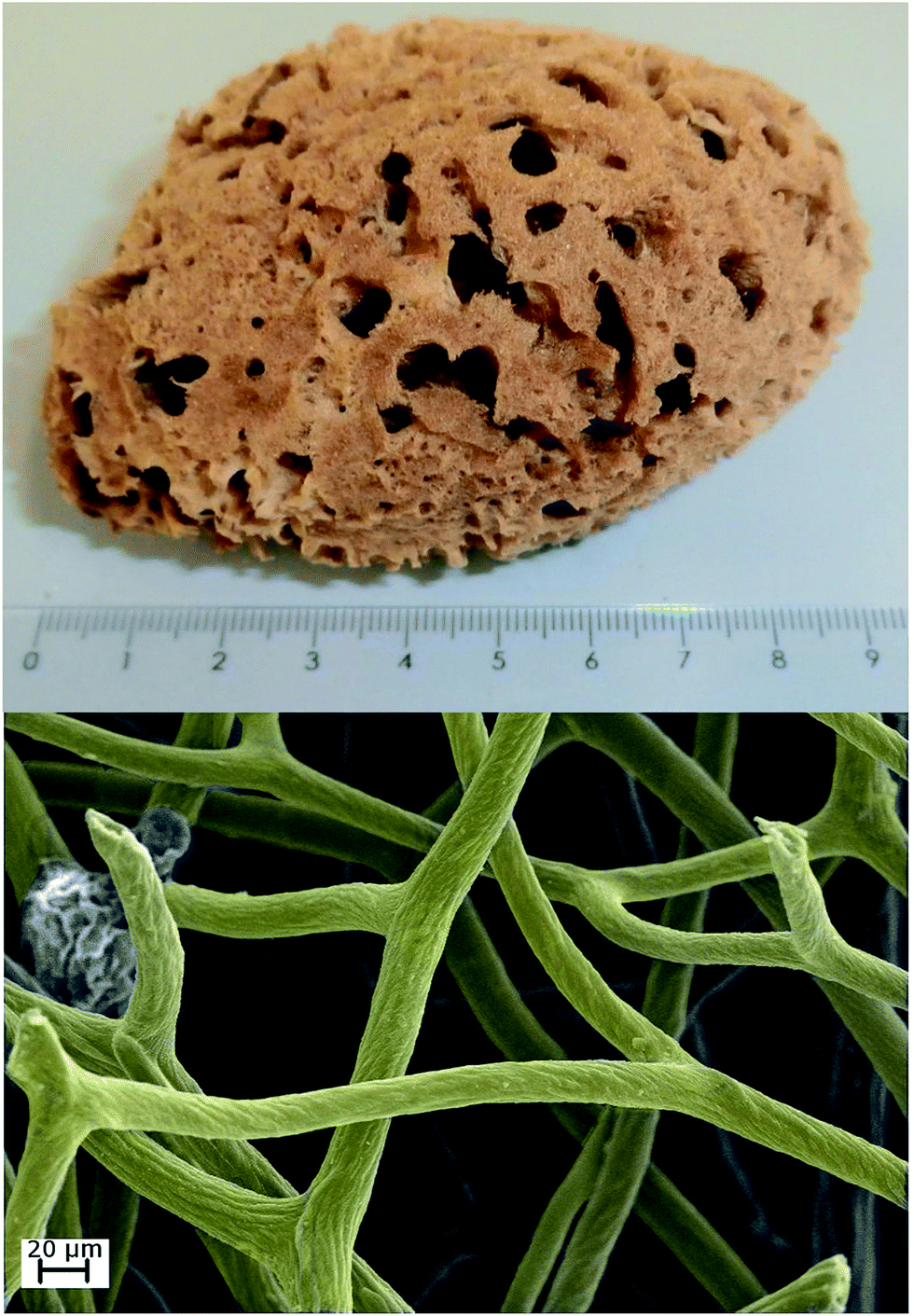 | ||
| Fig. 1 A photograph of H. communis marine sponge (up); colored SEM photograph of three-dimensional porous structure of H. communis spongin-based skeleton (down). | ||
Experimental
Fragments of sponge skeleton were collected from the Mediterranean sea at Tunisia's coast and cleaned according to standard procedures of sponge treatment, during which they are allowed to decay for 2 days while washing in sea water. The thoroughly washed sponge skeletons were directly provided by INTIB GmbH (Germany).Prior to the use of sponge in the synthesis of the composite, the sponge fragments were thoroughly washed with running water in order to remove any major contamination in form of sand, rocks and shell fragments. Afterwards, the specimens were purified with use of 3 M HCl in order to remove natural impurities in form of calcium carbonates.
Iron(III) chloride and hematite standard was obtained from Sigma-Aldrich (Germany). Deionized ultrapure water was used in all experiments.
Hydrothermal synthesis of the α-Fe2O3–spongin composite
Synthesis of the α-Fe2O3–spongin composite was performed by forced hydrolysis of iron(III) chloride and consisted of two stages. Firstly, the synthesis of hematite nucleation sites via hydrolysis of ferric chloride, and secondly the growth of hematite crystals onto fibers of the marine sponge skeleton under hydrothermal conditions.Synthesis of hematite particles was based on the procedure reported by Jiang et al.37 Synthesis procedure of iron oxide particles was composed of three steps. Firstly, 0.3 g of anhydrous FeCl3 was dissolved in 10 ml of ultra-pure water, followed by vigorous stirring to ensure that all the powder was dissolved. The transparent brownish solution was added to a conical flask containing 90 ml of hot ultra-pure water (90 °C) and 0.75 ml of 1.0 M HCl, and stirred with a magnetic stirrer. The mixture and a H. communis sponge skeleton specimen (1 × 1 × 3 cm) was transferred into Teflon-lined stainless steel (200 ml) hydrothermal reactor (Parr, USA) and maintained at 90 °C for 48 h. The obtained α-Fe2O3–spongin composite was washed ultrasonically in distilled water for 20 min in an ultrasound bath (Elmasonic GmbH, Germany) to remove any unattached particles of iron oxide, and dried in an air dryer at 50 °C for 24 h.
X-ray photoelectron spectroscopy
X-ray photoelectron spectroscopy was performed using an ESCALAB 250Xi (Thermo Scientific, USA) equipped with a monochromatic Al Kα X-ray source (1486.6 eV) which was focused to spot size of 650 μm, and operated at 14.8 kV and 19.1 mA. Scans were taken with a pass energy of 20 eV. The binding energies were corrected for the charge shift using the C 1s peak (BE = 284.6 eV) as reference.Raman measurements
The Raman measurements were performed using a LabRam HR 800 spectrometer (Horiba Jobin Yvon, France) equipped with a 600 grooves per mm grating and a Peltier cooled CCD detector. The spectra were measured in the backscattering configuration with the laser light being focused on the samples and collected through a 100× objective of an Olympus microscope. For excitation the 785 nm line of a diode laser was used. The laser power was chosen in order to avoid damage of the sample surface during the measurements, and was set at 1.2 mW for the measurements of the hematite structures and 10 mW for the measurements of the α-Fe2O3–spongin composite. For spongin containing samples 50 scans were accumulated with 10 s of acquisition time per each accumulation.High resolution transmission electron microscopy
HR-TEM was carried out using a spherical corrected JEOL ARM200F High Resolution Transmission Electron Microscope (Japan) at an accelerating voltage of 200 kV. Specimens for the HR-TEM analysis were prepared according to the standard procedures; i.e. a single drop of nanocomposite ultrasonically suspended in ethanol was placed on the electron microscopy grid of carbon (Ted Pella), and dried at room temperature under reduced pressure.Scanning electron microscopy
Morphological and microstructural properties of the selected spongin fragments before and after hydrothermal synthesis of hematite were examined using SEM images recorded with an Ultra 55 microscope (Carl Zeiss AG, Germany). Prior to testing, the samples were coated with carbon over a period of 45 s using an Edwards S150B sputter coater.Electrochemical measurements
For electrochemical studies, the capacitors have been assembled in a Swagelok® type cells by sandwiching two electrodes and using fiber glass material as a separator. The pellets for electrochemical measurements consisted of 85% of the α-Fe2O3–spongin composite, 10% of binder (polyvinylidene fluoride – PVDF Kynar Flex 2801) and 5% of acetylene black. The active materials used were commercially available activated carbon Norit® DLC Supra 30 (S30) with a surface area of 1588 m2 g−1, the α-Fe2O3–spongin composite, and a mixture of 80% activated carbon Norit® DLC Supra 30 with 20% of the obtained composite (S30 (80%) + α-Fe2O3–spongin composite (20%)).The mass of the electrodes was in the range of 7 to 9 mg and a geometric surface area of one electrode was 0.8 cm2. As an electrolyte for electrochemical measurements 6 mol l−1 KOH was used.
The studies of electrochemical properties were carried out on a multichannel potentiostat/galvanostat (Biologic VSP, France) to evaluate the capacitance properties of symmetric and asymmetric electrode systems. The capacitance properties were estimated by galvanostatic charge/discharge (100–1000 mA g−1), cycling voltammetry (CV; 1–100 mV s−1) and by electrochemical impedance spectroscopy (100 kHz to 1 mHz).
Results and discussion
SEM
SEM photographs (Fig. 2) show the fibrous spongin-based skeleton of H. communis before (Fig. 2A) and after (Fig. 2B–D) hydrothermal synthesis of hematite. The remaining photographs (Fig. 2C and D) reveal that the spongin fibers are completely covered with hematite nanoparticles, leaving little doubts as to the affinity of spongin for the iron compounds. Importantly, the hematite was formed exclusively on the surface of spongin fibers, not inside in contrary to chitin template, as shown by Wysokowski et al.38 The α-Fe2O3 particles are embedded into the spongin fibers strongly enough that they are not removed even during washing in an ultrasonic bath. Though individual nanoparticles are significantly small (see HR-TEM results, Fig. 3), the presence of agglomerates was detected. The size of the hydrodynamic diameter of agglomerates in a control sample (dispersion of Fe2O3 without spongin template) was measured with use of Non-Invasive Back Scattering method (NIBS) (see Fig. S1 ESI†). The results indicate that the highest volumetric contribution can be assigned to the agglomerates with sizes of 105.7 nm, equal to 22.2%.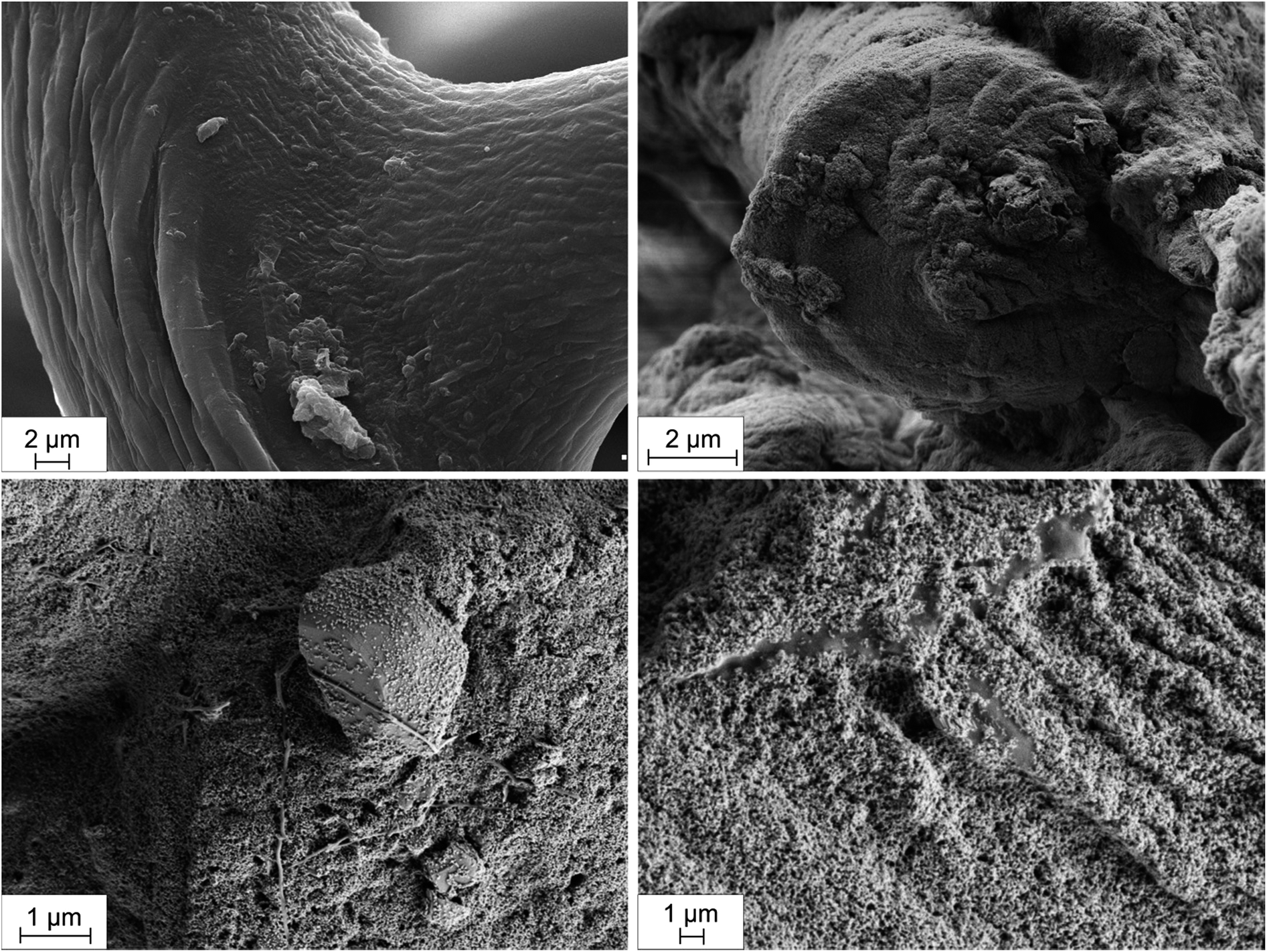 | ||
| Fig. 2 SEM photographs of H. communis spongin fibers before (A) and after (B–D) hydrothermal reaction with respect to obtaining of hematite. | ||
 | ||
| Fig. 3 HR-TEM photographs of the hematite nanoparticles on selected spongin nanofiber with spacing measurement of lattice and FFT digital diffractogram calculated from the marked area. | ||
Intriguingly, Fig. 2d shows a well-developed crystal of hematite which is surrounded by a single fibril of spongin. The photograph indicates that the spongin fibril was stretched out from the fiber due to hematite nanoparticle, pointing at possible grafting and growth of crystals directly on the surface of spongin fibers.
HR-TEM and XRD
The analysis of the diffraction pattern and the Fast Fourier Transformed (FFT) HR-TEM images was performed using the Digital Micrograph package. For confirmation of the presence of crystalline hematite in the α-Fe2O3–spongin composite we used HR-TEM analysis. Particles observed in Fig. 3 possess spherical shape with an average size of 5 nm in diameter. The indexed FFT from the HR-TEM micrograph refers to a particle with [001] zone axis orientation. The interplanar distances between the adjacent lattice fringes is 2.51 Å, corresponding to d(110). According to the ICDD PDF-4+ database the obtained data suggest the presence of crystalline α-Fe2O3. Additionally, XRD patterns of the α-Fe2O3–spongin composite, compared with hematite standard sample, were measured in order to investigate the crystallographic parameters of the obtained material, and identify typically occurring contaminations e.g. γ-Fe2O3 and Fe3O4 (Fig. S2 ESI†). The pattern obtained for the composite material matches the hematite standard sample, showing all the characteristic peaks according to the 33-664 JCPDS card. Moreover, the presence of other types of iron oxides was not detected.Thermogravimetric analysis
Important information regarding the thermal behavior of the α-Fe2O3–spongin composite were delivered by thermogravimetric analysis performed in air conditions, which was compared with the pure sponge skeleton and a hematite standard (Fig. S3 ESI†). The TG curve for the hematite standard shows a moderate decline of sample mass, most likely related to a loss of chemically and physically adsorbed water molecules. Thermograms of spongin as well as of the α-Fe2O3–spongin composite shows a behavior similar to each other. In the temperature range from room temperature to 160 °C, a mass loss of adsorbed water by as much as 3.7% can be observed which is then followed by a major loss of samples mass equal to about 50.8% corresponding to a thermal degradation of natural skeleton in range from 160 to 450 °C. The majority of total loss of sample mass can be attributed to the degradation of organic matrix of the composite. However, from the curve of sponge skeleton (blue line) it can be noticed that 27% of the initial mass sample still remains after heating up to 1000 °C. The remaining mass of α-Fe2O3–spongin composite sample, equal to about 49.2%, subtracted by the retained mass of pure sponge skeleton provide an important information about the composition of the final composite, showing that 22.2% of the α-Fe2O3–spongin composite is composed of hematite.XPS
The XPS analysis delivers important information regarding the formation mechanism of hematite onto the spongin support. XPS wide scan (Fig. S4 ESI†) of spongin identifies carbon, nitrogen, and oxygen as the main constituents of the collagenous skeleton. The photoelectron peaks corresponding to O 1s, N 1s, and C 1s orbitals are found at binding energies of 533 eV, 401 eV, and 285 eV, respectively. Moreover, a peak of smaller intensity at binding energy 164 eV relates to the presence of sulfur (orbital S 2p) involved in disulfide bonds of cystine, which presence was also found in spongin.13,37 The spectrum is very similar to the results obtained for keratin, which justifies use of term pseudokeratin as an early name of spongin.40–42In the Fig. 4, the XPS spectrum corresponding to the Fe 2p orbital of the hematite standard was compared with the spectrum of α-Fe2O3–spongin composite. The hematite standard shows characteristic peaks at 713.1 (Fe 2p3/2) and 727.3 eV (Fe 2p1/2) which are in agreement with reported values for a typical α-Fe2O3.43–46 Additionally, a satellite peak, located at 718.2 eV, approximately 8 eV above the Fe 2p3/2 main peak of hematite, is clearly distinguishable and does not overlap with any of the main peaks of iron.47,48 Interestingly, peaks corresponding to the same orbitals observed for the α-Fe2O3–spongin composite are shifted toward lower values of binding energy, respectively, down to 710.7 and 725.0 eV. The observation indicates a decrease in the oxidation state of iron from Fe3+ to Fe2+. This might result from the reaction of the sulfur from cystine residues present in spongin, with the iron of hematite, similar to the case described by Vieira et al. and Linert et al.49,50
 | ||
| Fig. 4 High-resolution XPS spectra presenting Fe 2p peaks of the hematite standard (red line) and the α-Fe2O3–spongin composite (green line). | ||
In the high resolution XPS spectrum of S 2p orbital (Fig. 5) of pure spongin (blue line) two peaks can be identified: one at 164 eV, attributed to disulfide bonds of cystine residues (–C–S–S–C–; S2+); and one at 168 eV, which indicates either sulfenic (Cys-SOH; S2+), sulfinic (Cys-SO2H; S4+) or sulfonic (Cys-SO3H; S6+) acid.51–53
 | ||
| Fig. 5 High-resolution XPS spectra showing S 2p peaks of spongin and the α-Fe2O3–spongin composite. | ||
Numerous reports have shown evidence that spongin of demosponges is similar to the collagen type IV of metazoans,13,39,54–56 in terms of the classic collagenous Gly–Xaa–Yaa motif, where hydroxyproline (Hyp) occupies any one of the positions in the triplet motif, other than that of glycine (Gly).57,58 However, the fibrillar spongin contains cysteine and/or cystine residues of varying content (0.5–1.0% wt), as well.39,59–61 Therefore, spongin, similarly to other polymeric organic substances, contains a large number of hydrophilic functional groups (–COO–, –OH, –CONH2, –RO–, –RS–, etc.). These functional groups containing electron donor elements (O, N and S) are capable of complex formation with metal ions.62,63 We believe that functional groups originating from amino acids, including sulfur of cystine/cysteine might play a crucial role in the process of iron mineralization; which is a common phenomenon for demosponges in nature.34,35
Based on the obtained results and reported studies we propose a plausible mechanism of formation of interactions between α-Fe2O3 nanoparticles and spongin fibers (Fig. 6). The mechanism of the composite formation would involve adsorption of nucleation sites on the surface of the fibers, and subsequent bond formation between Fe(III) atoms and oxygen atoms through hydrogen and covalent bonds, as well as a plausible chelation effect, as reported by Wysokowski et al.38 The hematite particles might be additionally bonded with sulfur moieties present in cysteine residues, as reported by previous studies.49,50,64
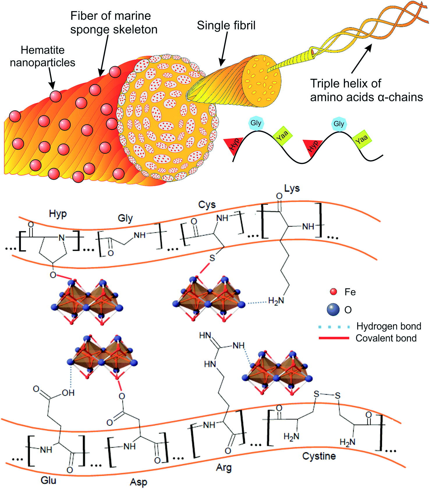 | ||
| Fig. 6 A scheme for a plausible mechanism of interaction between α-Fe2O3 and fibrous skeleton of H. communis after hydrothermal synthesis at 90 °C. | ||
Raman spectroscopy
Raman spectroscopy, as a fast and nondestructive analytical technique, was used to determine qualitative properties of the crystalline product. The analysis was performed for the α-Fe2O3–spongin composite and compared with hematite standard as well as unmodified spongin fibers (Fig. 7). Raman spectra for hematite crystals are characteristic, and can be easily distinguished from the common impurities such as Fe3O4 or γ-Fe2O3. In the Raman spectrum of hematite seven peaks are expected, namely two A1g modes (226 cm−1 and 497 cm−1), and five Eg modes (245 cm−1, 293 cm−1, 298 cm−1, 412 cm−1 and 613 cm−1). The position of peaks in the spectrum measured for hematite standard fit the expectations and are in a good agreement with literature data.65–67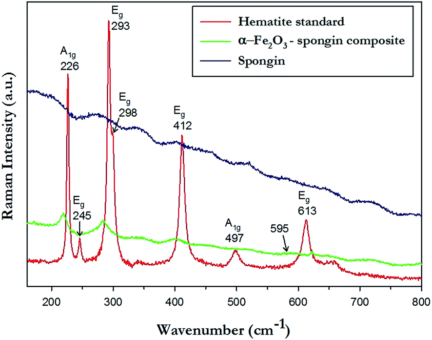 | ||
| Fig. 7 Raman spectra of hematite standard, spongin and α-Fe2O3–spongin composite. | ||
The Raman spectra of α-Fe2O3–spongin composite demonstrates four important peaks which fit the characteristic peaks of hematite standard, namely one A1g mode (220 cm−1), and three Eg modes (236 cm−1, 283 cm−1, 400 cm−1). The very small intensity of the peak around 595 cm−1 which is related to the crystal structure disorder, and contamination with meghemite or magnetite, suggest good homogeneity within the obtained crystalline material.68,69
Electrochemical studies
The electrochemical studies (Fig. 8) were performed in order to examine the potential usability of the obtained material as a component for a capacitor. According to the configuration of electrodes, capacitors can be divided into symmetric and asymmetric types. In this study, both types were constructed for comparison of operating parameters. Two- and three-electrode cells were examined using alkaline (6 M KOH) electrolyte. The electrolyte was chosen based on the literature data, and considering the fact that α-Fe2O3 operates well in high pH.70 | ||
Fig. 8 (A) Cyclic voltammograms of pellets of composite (α-Fe2O3–spongin composite) mixed with activated carbon Supra DLC 30 (20![[thin space (1/6-em)]](https://www.rsc.org/images/entities/char_2009.gif) :80) at 10 mV s−1 scan rate (two-electrode cell); (B) capacitance vs. frequency dependence of the composite blend (α-Fe2O3–spongin composite) with activated carbon Supra DLC 30 (20:80); (C) cyclic voltammograms at 5 mV s−1 scan rate for the three-electrode cell. :80) at 10 mV s−1 scan rate (two-electrode cell); (B) capacitance vs. frequency dependence of the composite blend (α-Fe2O3–spongin composite) with activated carbon Supra DLC 30 (20:80); (C) cyclic voltammograms at 5 mV s−1 scan rate for the three-electrode cell. | ||
The cycle voltammetry and electrochemical impedance spectroscopy studies were carried out to measure the capacity of the system. In the asymmetric capacitor, the α-Fe2O3–spongin composite was used as a negative electrode (anode). The considerable increase of capacitance of this kind of electrode system in comparison to a symmetric system with two electrodes made of activated carbon is presented in the voltammetry characteristics at 10 mV s−1 (Fig. 8A). The capacitance of the asymmetric capacitor containing the composite was equal to 100 F g−1 while for the symmetric capacitor of activated carbon it amounted to 86 F g−1.
Activated carbon was used as an enhancer of the electrode porosity and specific surface area. Since the energy of capacitors is stored in the electrical double layer, increased porosity directly influences its capacity. The capacitance of the symmetric system based only on α-Fe2O3–spongin composite was equal to 0.4 F g−1. Similar results were obtained by Zhao et al.70 for electrodes composed of Fe2O3 with multiwall nanotubes applied in symmetric and asymmetric systems. They reached the 33 F g−1 for asymmetric, and 8.5 F g−1 for the symmetric electrode of MWNTs.70 Low values of capacitance can be explained by the low conductivity of hematite.71,72 However, the addition of activated carbon enhanced this parameter. Moreover, the supplementation of the electrode with activated carbon improves the available surface area for electrolyte ions, and results in better exploitation.
The materials were tested over 5000 cycles using 1 A g−1. After cycleability measurements (made only in symmetric system) with α-Fe2O3–spongin composite as the electrode material, a 10% decrease of specific capacitance was observed.
As was already mentioned, the use of a negative electrode with the addition of the α-Fe2O3–spongin composite is very useful. The capacitance of the anode in asymmetric system is about 20% larger than in a symmetric capacitor of activated carbon, while the value of this parameter for positive electrode does not change.
As has been demonstrated above, the asymmetric capacitors have the best operative parameters. This was also shown with electrochemical impedance spectroscopy study (Fig. 8). An improvement of charge propagation for the electrode system with anodes based on the α-Fe2O3–spongin composite can be observed. Moreover the capacitance vs. frequency response showed probable pseudocapacitance reactions, as described by Wang et al.71
A shift of the cyclic voltammogram of the anode in the asymmetric system, and reduction of the peak resembling gaseous oxygen extraction, is observable. Moreover, both electrodes in the asymmetric capacitor showed a regular rectangle shape and perfect charge propagation (Fig. 8C).
Several notes concerning use of sponge-like structures in respect to electrochemical studies are found in the current literature. For instance, Luo et al. obtained a structure similar to natural sponge by carbonization of tartrate sodium, and used this material as electrodes in symmetric capacitors. Materials based on the tartrate sodium carbonized at different temperatures showed capacities between 84 to 53 F g−1. The further modification of these types of carbon materials is important to improve their electrochemical properties.73
Zhong et al. showed that the carbon spongy structure can be used as base for compound deposition.74 The 3-D, highly porous carbon nanotube sponges can be prepared by using chemical vapor deposition method. These materials were obtained using polyaniline deposition. They have shown good conductive properties and capacitance (1.85–1.62 F cm−2). Zhong et al. showed that the sponge structure is a very useful base for further modification.
The other example of capacitor materials using hematite mixed with carbon material was examined by Abdi and Trari.75 As a carbon material they used graphite powder. They synthesized nonstoichiometric hematite using a sol–gel method. The electrodes from synthesized materials were characterized by low values of capacitance: 4.915 F g−1 in 1 M NaOH electrolyte and 48.21 F g−1 in 1 M Na2SO3 electrolyte (at scan rate of 5 mV−1).
Conclusions
Both bio-inspired materials science and extreme biomimetics are evolving rapidly, and give birth to a broad variety of functional materials with designed mechanical and physicochemical properties. The anastomosed three-dimensional structure of H. communis marine sponge skeleton might be of particular use to incorporate inorganic nanomaterials exhibiting electronic, photonic, catalytic or bioactive properties. In this study we used the marine sponge spongin as a template for synthesis of hematite under hydrothermal conditions. The α-Fe2O3 crystals seem to entirely cover the surface of spongin fibers, and be tightly embedded into their external fragments; indicating high affinity of the skeleton of H. communis toward iron oxide nanoparticles.The presented results have shown that the spongin is a thermally stable biopolymer and capable of withstanding harsh conditions maintained during the whole procedure. Thus it is a very attractive material for a wide range of applications, including nanotechnology and biomaterials science. It was also shown that α-Fe2O3–spongin composite enhanced the electrochemical properties of the capacitor electrode, though still more research to fully characterize its properties remains to be accomplished.
Acknowledgements
This work was financially supported by European grant POKL.04.01.01-00-049/13, “Developing education in the field of nanotechnology at Poznan University of Technology based on cooperation with the NanoBioMedical Centre UAM and Universita degli Studi di Trieste”, National Centre for Research and Development research grant “Nanomaterials and their application to biomedicine” contract number PBS1/A9/13/2012, PUT research grants 03/32/DSPB/0506/2015 and 03/31/DSPB/0298, DFG Grant EH 394/3, BHMZ Programme of Erich-Krüger-Foundation (Germany) at TU Bergakademie Freiberg, and BMBF within the project CryPhys Concept (03EK3029A).Notes and references
- M. Wysokowski, I. Petrenko, A. Stelling, D. Stawski, T. Jesionowski and H. Ehrlich, Polymers, 2015, 7, 235–265 CrossRef CAS.
- M. Wysokowski, M. Motylenko, J. Beyer, A. Makarova, H. Stöcker, J. Walter, R. Galli, S. Kaiser, D. Vyalikh, V. V. Bazhenov, I. Petrenko, A. L. Stelling, S. L. Molodtsov, D. Stawski, K. J. Kurzydłowski, E. Langer, M. V. Tsurkan, T. Jesionowski, J. Heitmann, D. C. Meyer and H. Ehrlich, Nano Res., 2015, 8, 2288–2301 CrossRef CAS.
- H. Ehrlich, P. Simon, M. Motylenko, M. Wysokowski, V. V Bazhenov, R. Galli, A. L. Stelling, D. Stawski, M. Ilan, H. Stöcker, B. Abendroth, R. Born, T. Jesionowski, K. J. Kurzydłowski and D. C. Meyer, J. Mater. Chem. B, 2013, 1, 5092–5099 RSC.
- M. Wysokowski, M. Motylenko, V. V. Bazhenov, D. Stawski, I. Petrenko, A. Ehrlich, T. Behm, Z. Kljajic, A. L. Stelling, T. Jesionowski and H. Ehrlich, Front. Mater. Sci., 2013, 7, 248–260 CrossRef.
- M. Wysokowski, M. Motylenko, H. Stöcker, V. V. Bazhenov, E. Langer, A. Dobrowolska, K. Czaczyk, R. Galli, A. L. Stelling, T. Behm, Ł. Klapiszewski, D. Ambrożewicz, M. Nowacka, S. L. Molodtsov, B. Abendroth, D. C. Meyer, K. J. Kurzydłowski, T. Jesionowski and H. Ehrlich, J. Mater. Chem. B, 2013, 1, 6469–6476 RSC.
- H. Ehrlich, M. Maldonado, K. Spindler, C. Eckert, T. Hanke, R. Born, C. Goebel, P. Simon, S. Heinemann and H. Worch, J. Exp. Zool., 2007, 356, 347–356 CrossRef PubMed.
- H. Ehrlich, M. Ilan, M. Maldonado, G. Muricy, G. Bavestrello, Z. Kljajic, J. L. Carballo, S. Schiaparelli, A. Ereskovsky, P. Schupp, R. Born, H. Worch, V. V. Bazhenov, D. Kurek, V. Varlamov, D. Vyalikh, K. Kummer, V. V. Sivkov, S. L. Molodtsov, H. Meissner, G. Richter, E. Steck, W. Richter, S. Hunoldt, M. Kammer, S. Paasch, V. Krasokhin, G. Patzke and E. Brunner, Int. J. Biol. Macromol., 2010, 47, 132–140 CrossRef CAS PubMed.
- H. Ehrlich, E. Steck, M. Ilan, M. Maldonado, G. Muricy, G. Bavestrello, Z. Kljajic, J. L. Carballo, S. Schiaparelli, A. Ereskovsky, P. Schupp, R. Born, H. Worch, V. V Bazhenov, D. Kurek, V. Varlamov, D. Vyalikh, K. Kummer, V. V Sivkov, S. L. Molodtsov, H. Meissner, G. Richter, S. Hunoldt, M. Kammer, S. Paasch, V. Krasokhin, G. Patzke, E. Brunner and W. Richter, Int. J. Biol. Macromol., 2010, 47, 141–145 CrossRef CAS PubMed.
- H. Ehrlich, J. K. Rigby, J. P. Botting, M. V. Tsurkan, C. Werner, P. Schwille, Z. Petrášek, A. Pisera, P. Simon, V. N. Sivkov, D. V. Vyalikh, S. L. Molodtsov, D. Kurek, M. Kammer, S. Hunoldt, R. Born, D. Stawski, A. Steinhof, V. V. Bazhenov and T. Geisler, Sci. Rep., 2013, 3, 3497 CAS.
- R. Garrone, Phylogenesis of connective tissue: morphological aspects and biosynthesis of sponge intercellular matrix, S. Karger, Basel; New York, 1978 Search PubMed.
- J. Gross, Z. Sokal and M. Rougvie, J. Histochem. Cytochem., 1956, 4, 227–246 CrossRef CAS PubMed.
- J.-Y. Exposito, C. Larroux, C. Cluzel, U. Valcourt, C. Lethias and B. M. Degnan, J. Biol. Chem., 2008, 283, 28226–28235 CrossRef CAS PubMed.
- A. Aouacheria, C. Geourjon, N. Aghajari, V. Navratil, G. Deléage, C. Lethias and J.-Y. Exposito, Mol. Biol. Evol., 2006, 23, 2288–2302 CrossRef CAS PubMed.
- S. Junqua, L. Robert, J. Vacelet, R. Garrone, M. P. De Ceccatty and J. Vacelet, Connect. Tissue Res., 1974, 2, 193–203 CrossRef CAS PubMed.
- H. Ehrlich, Biological Materials of Marine Origin: Invertebrates, Springer, Dordrecht, Heidelberg, London, New York, 2010 Search PubMed.
- D. Louden, S. Inderbitzin, Z. Peng and R. de Nys, Aquaculture, 2007, 271, 275–285 CrossRef.
- R. M. Cornell and U. Schwertmann, The Iron Oxides, Wiley-VCH, Weinheim, 2003 Search PubMed.
- T. Jesionowski and F. Ciesielczyk, in Encyclopedia of Color Science and Technology, ed. R. Luo, Springer, 2014, pp. 1–21 Search PubMed.
- Y. Wang, J. Cao, M. Yu, G. Sun, X. Wang and H. Bala, Mater. Lett., 2013, 100, 102–105 CrossRef CAS.
- G. Picasso, M. R. S. Kou, O. Vargasmachuca, J. Rojas, C. Zavala, A. Lopez and S. Irusta, Microporous Mesoporous Mater., 2014, 185, 79–85 CrossRef CAS.
- Q. Liu, Y. Yang, B. Sun, D. Su, Z. Li, Q. Xia and G. Wang, Sens. Actuators, B, 2014, 194, 27–32 CrossRef CAS.
- H.-J. Song, X. Jia and X.-Q. Zhang, J. Mater. Chem., 2012, 22, 22699–22705 RSC.
- K. Sivula, F. Le Formal and M. Grätzel, ChemSusChem, 2011, 4, 432–449 CrossRef CAS PubMed.
- Y. Hu, A. Kleiman-Shwarsctein, A. J. Forman, D. Hazen, J. Park, E. W. Mcfarland and S. Barbara, Chem. Mater., 2008, 20, 3803–3805 CrossRef CAS.
- K. Sivula, R. Zboril, F. Le Formal, R. Robert, A. Weidenkaff, J. Tucek, J. Frydrych and M. Grätzel, J. Am. Chem. Soc., 2010, 132, 7436–7444 CrossRef CAS PubMed.
- A. Kay, I. Cesar and M. Grätzel, J. Am. Chem. Soc., 2006, 128, 15714–15721 CrossRef CAS PubMed.
- N. D. Phu, D. T. Ngo, L. H. Hoang, N. H. Luong, N. Chau and N. H. Hai, J. Phys. D. Appl. Phys., 2011, 44, 345002 CrossRef.
- H. Itoh and T. Sugimoto, Colloid Interface Sci., 2003, 265, 283–295 CrossRef CAS.
- J. Chen, L. Xu, W. Li and X. Gou, Adv. Mater., 2005, 17, 582–586 CrossRef CAS.
- Y. Wan, X. Shi, H. Xia and J. Xie, Mater. Res. Bull., 2013, 48, 4791–4796 CrossRef CAS.
- D. Chen, H. Quan, J. Liang and L. Guo, Nanoscale, 2013, 5, 9684–9689 RSC.
- P. Thanikaivelan, N. T. Narayanan, B. K. Pradhan and P. M. Ajayan, Sci. Rep., 2012, 2, 230–237 Search PubMed.
- C. J. Geoffroy, Mémoires de l'Académie Royale des Sciences, 1705, 660–661 Search PubMed.
- K. M. Towe and K. Rützler, Science, 1968, 162, 268–269 CAS.
- J. Vacelet, B. Verdenal and G. Perinet, Biol. Cell, 1988, 62, 189–198 CrossRef CAS.
- R. Pronzato, Aquat. Conserv. Mar. Freshw. Ecosyst., 1999, 493, 485–493 CrossRef.
- X. C. Jiang, a. B. Yu, W. R. Yang, Y. Ding, C. X. Xu and S. Lam, J. Nanoparticle Res., 2009, 12, 877–893 CrossRef.
- M. Wysokowski, M. Motylenko, J. Walter, G. Lota, J. Wojciechowski, H. Stöcker, R. Galli, A. L. Stelling, C. Himcinschi, E. Niederschlag, E. Langer, V. V. Bazhenov, T. Szatkowski, J. Zdarta, I. Pertenko, Z. Kljajić, T. Leisegang, S. L. Molodtsov, D. C. Meyer, T. Jesionowski and H. Ehrlich, RSC Adv., 2014, 4, 61743–61752 RSC.
- J.-Y. Exposito, C. Cluzel, R. Garrone and C. Lethias, Anat. Rec., 2002, 268, 302–316 CrossRef CAS PubMed.
- R. Molina, P. Jovančić, D. Jocić, E. Bertran and P. Erra, Surf. Interface Anal., 2003, 35, 128–135 CrossRef CAS.
- R. J. J. Ward, H. A. Willis, G. A. George, G. B. Guise, R. J. Denning, D. J. Evans and R. D. Short, Text. Res. J., 1993, 63, 362–368 CrossRef CAS.
- A. Hesse, H. Thomas and H. Höcker, Text. Res. J., 1995, 65, 371–378 CrossRef CAS.
- Z. An, J. Zhang, S. Pan and G. Song, Powder Technol., 2012, 217, 274–280 CrossRef CAS.
- X. Fei, Z. Shao and X. Chen, J. Mater. Chem. B, 2013, 1, 213–220 RSC.
- H. Srivastava, P. Tiwari, A. K. Srivastava and R. V. Nandedkar, J. Appl. Phys., 2007, 102, 054303 CrossRef.
- M. Mahadik, S. Shinde, V. Mohite, S. Kumbhar, K. Rajpure, A. Moholkar, J. Kim and C. Bhosale, Mater. Express, 2013, 3, 247–255 CrossRef CAS.
- B. Ahmmad, K. Leonard, S. Islam, J. Kurawaki, M. Muruganandham, T. Ohkubo and Y. Kuroda, Adv. Powder Technol., 2013, 24, 160–167 CrossRef CAS.
- A. A. Tahir, K. G. U. Wijayantha, S. Saremi-Yarahmadi, M. Mazhar and V. Mckee, Chem. Mater., 2009, 21, 3763–3772 CrossRef CAS.
- A. P. Vieira, G. Berndt, I. G. de Souza Junior, E. Di Mauro, A. Paesano, H. de Santana, A. C. S. da Costa, C. T. B. V. Zaia and D. A. M. Zaia, Amino Acids, 2011, 40, 205–214 CrossRef CAS PubMed.
- W. Linert, R. F. Jameson and E. Herlinger, Inorg. Chim. Acta, 1991, 187, 239–247 CrossRef CAS.
- R. H. Bradley, I. L. Clackson and D. E. Sykes, Surf. Interface Anal., 1994, 22, 497–501 CrossRef CAS.
- C. M. Carr, I. H. Leaver and A. E. Hughes, Text. Res. J., 1986, 56, 457–461 CrossRef CAS.
- G. Wen, J. A. Rippon, P. R. Brady, X. G. Wang, X. Liu and P. G. Cookson, Powder Technol., 2009, 193, 200–207 CrossRef CAS.
- R. Garrone, P. Guenin and M. Mazzorana, Ann. N. Y. Acad. Sci., 1985, 460, 434–438 CrossRef.
- J. Y. Exposito, R. Ouazana and R. Garrone, Eur. J. Biochem., 1990, 190, 401–406 CrossRef CAS PubMed.
- J. Y. Exposito, M. van der Rest and R. Garrone, J. Mol. Evol., 1993, 37, 254–259 CrossRef CAS PubMed.
- R. Pallela, S. Bojja and V. R. Janapala, Int. J. Biol. Macromol., 2011, 49, 85–92 CrossRef CAS PubMed.
- N. Boute, J. Y. Exposito, N. Boury-Esnault, J. Vacelet, N. Noro, K. Miyazaki, K. Yoshizato and R. Garrone, Biol. Cell, 1996, 88, 37–44 CrossRef CAS PubMed.
- P. R. Bergquist and D. W. Hartman, Mar. Biol., 1969, 3, 247–268 CrossRef CAS.
- K. A. Piez and J. Gross, Biochim. Biophys. Acta, 1959, 34, 24–39 CAS.
- J.-Y. Exposito and R. Garrone, Proc. Natl. Acad. Sci. U. S. A., 1990, 87, 6669–66673 CrossRef CAS.
- D. A. M. Zaia, Amino Acids, 2004, 27, 113–118 CrossRef CAS PubMed.
- K. Kandori, M. Sakai, S. Inoue and T. Ishikawa, J. Colloid Interface Sci., 2006, 293, 108–115 CrossRef CAS PubMed.
- L. Michaels and E. S. Guzman Barron, J. Biochem., 1929, 83, 191–210 Search PubMed.
- D. L. A. de Faria, S. V. Silva and M. T. de Oliviera, J. Raman Spectrosc., 1997, 28, 873–878 CrossRef CAS.
- B. Ahmmad, K. Leonard, M. Shariful Islam, J. Kurawaki, M. Muruganandham, T. Ohkubo and Y. Kuroda, Adv. Powder Technol., 2013, 24, 160–167 CrossRef CAS.
- J. Wang, W. B. White and J. H. Adair, J. Am. Ceram. Soc., 2005, 88, 3449–3454 CrossRef CAS.
- D. Bersani, P. P. Lottici and A. Montenero, J. Raman Spectrosc., 1999, 360, 355–360 CrossRef.
- A. M. Jubb and H. C. Allen, Appl. Mater. Interfaces, 2010, 2, 2804–2812 CrossRef CAS.
- X. Zhao, C. Johnston and P. S. Grant, J. Mater. Chem., 2009, 19, 8755–8760 RSC.
- D. Wang, Q. Wang and T. Wang, Nanotechnology, 2011, 22, 135604 CrossRef PubMed.
- A. Abdia and M. Trarib, Electrochim. Acta, 2013, 111, 869–875 CrossRef.
- H. Luo, Y. Yang, X. Zhao, J. Zang and Y. Chen, Electrochim. Acta, 2015, 169, 13–21 CrossRef CAS.
- Z. Jing, Y. Zhenyu, M. Rahul, T. Abhay Varghese, Z. Ke, S. Pengzhan, L. Jie, Z. Hongwei and K. Nikhil, Nano Energy, 2013, 2, 1025–1030 CrossRef.
- A. Abderrezak and M. Trari, Electrochim. Acta, 2013, 111, 867–875 Search PubMed.
Footnote |
| † Electronic supplementary information (ESI) available. See DOI: 10.1039/c5ra09379a |
| This journal is © The Royal Society of Chemistry 2015 |