Novel flame retardant flexible polyurethane foam: plasma induced graft-polymerization of phosphonates
Maude Jimenez*,
Nicolas Lesaffre,
Séverine Bellayer,
Renaud Dupretz,
Marianne Vandenbossche,
Sophie Duquesne and
Serge Bourbigot
UMET-ISP-R2FIRE, UMR 8207, ENSCL, BP90108, 59652 Villeneuve d'Ascq cedex, France. E-mail: maude.jimenez@univ-lille1.fr; Fax: +33 3 20 33 71 96; Tel: +33 3 20 33 71 96
First published on 21st July 2015
Abstract
Flame retardancy of flexible polyurethane foams has become an issue due to very severe regulations. To overcome the challenge of incorporating flame retardant (FR) additives during the foaming process without altering the foam properties, a plasma surface treatment was used for the first time in this work: a cold plasma induced graft-polymerization of phosphonate containing precursors (diethylvinylphosphonate-DEVP) with or without a crosslinking agent (1,4 butanedioldiacrylate) was applied on open cell flexible polyurethane foams (PUF). The flame retardant properties of these foams, before and after further rinsing, were evaluated using horizontal UL-94 test for 10 s and 60 s. One of the tested systems (DEVP + crosslinker), even after sonication, completely stops the melt dripping of the foams when exposed to the flame of the butane torch and charring occurs. This efficient surface treatment was characterized before and after burning by Scanning Electron Microscopy (SEM), electron probe microanalysis (EPMA), 31P solid state NMR and X-ray Photoelectron Spectroscopy (XPS). Its FR mechanism of action was then further investigated using microscale combustion calorimetry (MCC), thermogravimetric analyses coupled with infrared Fourier transform spectroscopy (TGA-FTIR), pyrolysis gas-chromatography coupled with mass spectrometry (GC-MS pyrolysis) and 31P solid state NMR. The results obtained show that it is necessary (i) to use the crosslinking agent, as DEVP mainly reacts with this crosslinker and (ii) to activate the PU foam before graft-polymerization to promote further reaction with the crosslinker. The characterizations also proved that before sonication, non-reacted DEVP precursors mainly act in the gas phase, preventing ignition, whereas after sonication the covalently grafted phosphorus containing species mainly act in the condensed phase to form phosphonic acid which will promote charring and thus will limit dripping and flame spread.
Introduction
Flexible polyurethane foams (PUF) are primarily used in furniture and the automotive industry. These foams burn rapidly, producing a large amount of heat and smoke. For example, flexible PUF in furniture and bedding is capable of setting a room to flashover in 5–10 min once ignited.1 As a result, in recent years, great attention has been paid in some countries to improve flame-retardant (FR) properties of flexible PUF due to strict standards being established both in home furniture safety and in traffic safety regulations.Flexible PUF flammability is usually minimized by incorporating during processing flame retardant additives, acting as flame retardants either on the basis of condensed-phase or gas-phase mechanisms. However, the most common FRs (e.g., brominated or chlorinated small molecules) for flexible PUF have been proven to be harmful both to human health and the environment,2,3 resulting in worldwide bans on the use of some of these compounds.4–6
These concerns have resulted in numerous studies addressing the issue of foam flammability with new FRs (phosphorus, silicon, …) in an attempt to achieve both minimal environmental impact and reduced foam flammability.7–10
Incorporating flame retardant additives in the bulk during FPUF processing is however a challenge, as both the foaming process and the mechanical behavior of the foam can be altered by these fillers.11,12 For that reason, another approach consisting in applying a surface treatment to concentrate the FR effect where it is crucially needed, i.e. on the surface of the material, appears as promising since it eliminates the issues related to the incorporation of FR. However, only few examples of this approach exist in the literature. In particular, recent major advances were published by Grunlan et al.13 and Laufer et al.14 on the development of layer-by-layer assembled carbon nanofiber-filled coatings and of sulfur based layer by layer assemblies to efficiently flame retard flexible PUF. Following this work, recent papers were published using this multilayer concept or a one pot coating concept.15–17 Other techniques, such as cold plasma, however exist to graft-polymerize functional precursors on various substrates such as textiles to bring some flame retardant properties to the materials. This technique was for example successfully applied to flame retard cotton, using plasma induced graft polymerization (PIGP) of acrylate phosphates,18–20 but the concept has never been applied to foams. Some papers also report the interesting use of phosphonate based compounds21 to flame retard flexible PUF in the bulk.9,10 For example, Wang et al. recently incorporated dimethyl methylphosphonate in a flexible PUF during foam processing.22
According to these different studies, our idea consists in graft-polymerizing by cold plasma a precursor containing both a vinyl function to favor the graft-polymerization onto the foam and a phosphonate function to provide a durable flame retardant action. The objective is indeed to keep this flame retardant effect even if the coated foam is washed. Liepins et al.23,24 and Sato et al.25 reported that dimethylvinylphosphonate (DMVP) and diethylvinylphosphonate (DEVP) exhibit fire retardant properties of interest. We chose in this paper to investigate the plasma graft-polymerization of diethylvinylphosphonate (DEVP) on open cell flexible polyurethane foams.
In the papers reporting the grafting of precursors such as acrylate phosphates on cotton fabrics, it is however mentioned that a crosslinking agent (e.g. ethyleneglycoldiacrylate or EGDA) is usually added to the precursor in order to obtain a good grafting rate after Soxhlet washing.19,26 A photoinitiator or plasma activation are also reported to increase the grafting rate.
In this paper, the influence of (i) the pre-activation of the foams, (ii) the use of a crosslinker and (iii) the plasma treatment conditions on the FR properties of the foams before and after sonication will thus be investigated. The flame retardant properties of the functional foams will first be evaluated by horizontal flame spread test and are presented in the first part of this paper. The characterizations by Scanning Electron Microscopy (SEM), electron probe microanalysis (EPMA), X-ray Photoelectron Spectroscopy (XPS) and 31P solid state NMR of the most efficient FR foams are then presented and the possible plasma grafting mechanism of DEVP is presented. In the last part of the paper, the flame retardant mechanisms of action of the plasma polymer are investigated using Microscale Combustion Calorimetry (MCC), thermogravimetric analyses coupled with infrared spectroscopy (TGA-FTIR), pyrolysis gas-chromatography coupled with mass spectrometry (py-GC/MS) and 31P solid state NMR.
Experimental
Materials
Samples (15 cm × 5 cm × 1.5 cm) were cut from open-cell flexible molded polyurethane (PU) foams provided by Saira Seats, France and cleaned in an ethanol–water ultrasonic bath for one hour before use. They were then dried for 12 hours in a heating chamber at 60 °C.The Saira Seats foams are composed of more than 98 wt% polyurethane and less than 2 wt% bis-chloromethylene bis(bis-2-chloroethyl)phosphate (Amgard V6, CAS no. 38051-10-4). They are obtained by (i) polymerization of a polyol on an isocyanate and (ii) release of carbon dioxide resulting from the polycondensation of an isocyanate on a water molecule. Both reactions occur simultaneously, and the components are added in stoichiometric amounts, in order to guarantee total polymerization and neutrality of each reactive function (hydroxyle, amine, isocyanate) and the obtention of an inert polymer, without any free monomer.
Surface modification
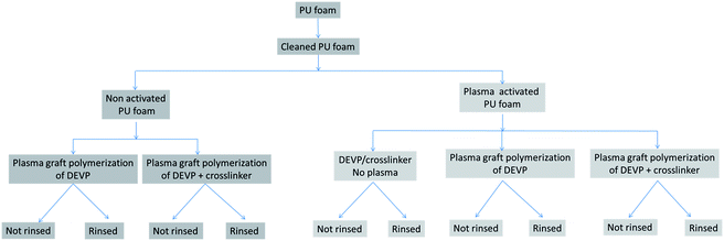
The scheme summarizing the experimental strategy is detailed in Fig. 1.Half of the clean and dried PUF samples panel was activated by low pressure plasma (Europlasma apparatus CD1200-400 COMBI MC, Radio Frequency generator Dressler, 13.56 MHz) with a pure argon flow (100 W, 180 s, 15 sccm). Both non activated and activated samples were then immersed for one minute in methanol containing 300 g L−1 diethyl vinyl phosphonate (DEVP) (provided by Sigma Aldrich) (Fig. 2a), containing or not a crosslinker: 20 wt% of 1-4 butanediol diacrylate (provided by Sigma Aldrich) (Fig. 2b). The samples were then padded one time using a roll-padder (KMS Colortech Service Co., Ltd) at 0.2 MPa.
They were then again submitted to pure argon low pressure cold plasma (100 W, 1200 s, 50 sccm) to graft-polymerize the DEVP onto and possibly inside the foam. In order to look at the grafting durability, some samples were finally sonicated for one hour in an ethanol–water bath and dried at ambient temperature whereas some others were not rinsed after plasma treatment.
One sample activated by plasma, immersed in the solution containing DEVP and the crosslinker but simply dried in an oven without plasma post-treatment was taken as reference.
All samples were weighed before activation and after DEVP plasma induced graft polymerization (without and with sonication) in order to evaluate the weight gain.
Surface characterizations
The morphologies of the virgin foam and of the most efficient DEVP-coated foam after rinsing were observed using a Scanning Electron Microscope Hitachi S4700 at an accelerating voltage of 6 kV and a current of 10 μA. Images were taken at ×30, ×500 and ×2000 magnifications.To analyse the chemical composition of samples, Electron Probe Microscopy Analyses (EPMA) were carried out on a CAMECA SX100. The samples were mainly analysed in cross-sections: they were embedded into an epoxy resin, polished (up to 1/4 μm) and carbon coated by means of a Bal-Tec SCD005 sputter coater. Back scattered electron (BSE) images of the cross sections were obtained at 15 kV, 15 nA. On BSE pictures, the darkest parts correspond to the “lightest” elements. Low and high magnification images were taken in various parts of the samples in order to have a representative picture. Phosphorus X-ray mappings were carried out at 15 kV and 40 nA.
Residues after burning were analysed by 31P solid-state NMR measurements using a Bruker Avance II 400 spectrometer. Bruker probe heads equipped with 4 mm MAS (Magic Angle Spinning) assembly were used. The experiments were carried out at 162 MHz using these parameters: number of scans was 16, recycling delay was 120 s, pulse length was 2.5 μs and spinning rate was 10 kHz. H3PO4 in aqueous solution (85%) was used as reference.
XPS analyses were performed on an Axis ultra DLD (Kratos analytical) using a monochromatic Al KR X-ray source (hm = 1486.6 eV). The emission voltage and the current of this source were set to 15 kV and 10 mA, respectively. The pressure in the analyzing chamber was maintained at 107 Pa or lower during analysis, and the size of the analyzed area was 300 × 700 μm2, with a depth of 10 nm.
Survey (0–1300 eV) spectra were recorded at pass energies of 160 eV with a step of 1 eV, and high-resolution (C1s) spectra were recorded at pass energies of 40 eV with a step of 0.1 eV.
Data treatment and peak-fitting procedures were performed using Casa XPS software. Obtained spectra were rescaled by shift of C1s C–C at 285 eV. The C1s peaks were decomposed using Gaussian–Lorentzian peak shapes and the full-width at half maximum (fwhm) of each line shape was maintained below 1.3 eV.
Fire testing
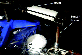
The samples were horizontally mounted in a support (Fig. 3) and the smallest side of the rectangle was exposed to a Bunsen burner flame for 10 s. In some cases, a second sample was exposed in the same conditions to the flame for 60 s. During both tests, (i) the dripping and the potential cotton ignition, (ii) the time of combustion after removing the flame, (iii) the char length and (iv) the self-extinguishment of the sample when the flame is removed were assessed.Videos of the tests were recorded, and pictures of the samples were taken before and after the test.
Thermal analyses
TG analyses were performed on a Q-5000 TA instruments apparatus. The thermograms were recorded in the 40–800 °C temperature range with a heating rate of 10 °C min−1 under nitrogen flow, Air Liquide grade (100 mL min−1). For each experiment, samples of 10 mg material were positioned on a gold sheet in alumina open pans.Gases released during the degradation of the virgin foam and of the coated foams were analysed using a TGA apparatus (TGA Q5000, TA Instrument) connected to a Fourier transformed infrared (FTIR) spectrometer (ThermoScientific) Nicolet iS10. The IR spectra were recorded between 400 cm−1 to 4000 cm−1 (spectra recorded every 5 s). For each experiment, samples of 10 mg material were positioned on a gold sheet in alumina open pans. All the analyses were carried out in nitrogen flow, Air Liquide grade (100 mL min−1). Combustion flow calorimeter (PCFC) (Fire Testing Technology, UK) was used to determine on a milligram scale the flammability characteristics of PUFs, following ASTM D7309. PCFC is a useful instrument to determine the fuel content of the decomposing volatile products and can also offer valuable insight into the action mechanism of the FRs. Each sample (approximately 7 mg) was exposed to a heating rate of 1 °C s−1 from 150 to 750 °C in the pyrolysis zone. Through MCC, the peak of heat release rate (pHRR) was measured in W g−1. All experiments were repeated in triplicate. Pyrolysis-GC/MS provides an extremely sensitive tool to determine the nature of gases evolved during the thermal decomposition of a material. The pyrolysis-GC/MS measuring system was provided by Shimadzu. A micro-furnace pyrolyzer (Frontier Lab PY-2020iD), a gas chromatograph equipped with a capillary column and a quadrupole mass spectrometer equipped with an Electron-Impact (EI) ionization source (Shimadzu GC/MS QP2010 SE) are directly connected in series. About 0.2 mg of the samples is added in a stainless steel sample cup. The latter is first placed at the upper position of the pyrolyzer, and then introduced into the center of the furnace (inside a quartz tube vial) under a helium gas flow. In the pyrolyzer furnace, the temperature was initially set at 35 °C and then raised to a defined temperature with a selected heating rate (generally 5 °C min−1). The temperature of the interface between the pyrolyzer and the GC injection port and the injection port were respectively set at 320 °C and 280 °C. A fused silica capillary column (30 m × 0.25 mm × 0.25 μm film thickness) was used and the linear velocity of helium as a carrier gas was 40 cm s−1. The GC column temperature was maintained at 35 °C during the whole temperature ramp of samples in the pyrolyzer and then programmed up to 300 °C at the rate of 5 °C min−1, followed by an isotherm of at least 10 min at 300 °C. The studied PU foam and DEVP-coated PU foam (rinsed or not) were submitted to a ramp of 10 °C min−1 from 35 to 800 °C in inert atmosphere (He) in the pyrolyzer, while volatile compounds were observed, and then the heavier compounds were desorbed. Electron-impact spectra were recorded at 85 eV with a mass scan rate of 2 scan per s. Pyrograms and mass spectra were treated using a GC/MS post-run analysis program (Shimadzu). The NIST and FSearch mass spectral databases were used for the identification of products. MSFragmenter tool, from ACDlabs, was used to help identifying synthesis molecules (not belonging to databases).
Results
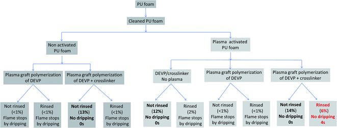
A screening of the samples described in Fig. 1 was carried out: the samples were weighed after plasma treatment, before and after sonication, and were then tested to the 10 s horizontal UL94 test. The results in terms of weight uptake and fire retardant properties are summarized in the Fig. 4.Most of the samples show an uptake percentage less than 1% after sonication. Only four samples lead to higher weight gain: three non-rinsed samples (14, 13 and 12% weight gain) and only one sonicated sample, i.e. the rinsed pre-activated plasma graft-polymerized foam using the solution containing both DEVP and the crosslinker, which shows a weight gain of 6%. This is the only sample that shows a significant weight gain after rinsing.
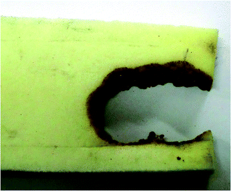
The FR performances of the samples were also evaluated using the horizontal UL 94 test for 10 s. The results in terms of dripping, which is a critical parameter, are summarized in Fig. 4 for all samples. Virgin PU foam ignites very rapidly and the molten PU drips and ignites the cotton placed in an aluminum pan under the foam. Since the dripping is very intense, the sample self-extinguishes. If the flame is applied on the foam a second time, the same phenomenon occurs. An example of burnt sample is shown in Fig. 5.
All coated samples exhibit dripping except the four foams with a weight uptake percentage above 6%. Dripping leads to self-extinguishment of the flame but in all cases the cotton placed beneath the foam ignites.
On the contrary, the foams with weight gains of 13%, 12%, 14% and 6% do not drip. Moreover, when the flame is removed from these samples after 10 s, flame stops quite instantaneously (0 s for the samples with weight uptakes of 13, 12 and 14% and 4 s for the washed sample with weight uptake of 6%).
According to the weight gain results, it seems that both pre-activation, plasma post-treatment and the use of the crosslinking agent are necessary to anchor the coating on the foam whereas in other cases only impregnation is obtained. Indeed, it is possible to assume that when the coating is not durable to washing, the polymer or monomers are present at the surface of the foam but without chemical bonding with the polyurethane foam, which explains the drop of weight gain after rinsing.
There is also a clear relationship between the uptake rate and fire test results. It is noteworthy that only 2% weight uptake is not sufficient enough to prevent dripping whereas 6% is, even after sonication.
In order to understand if the DEVP is covalently grafted on the PUF having a weight uptake of 6% after sonication and what is the FR mechanism of DEVP on the PUF before and after sonication, two characteristic samples were chosen for further investigation: the activated plasma graft-polymerized samples using the solution containing both DEVP and the crosslinking agent, before sonication (14% uptake) and after sonication (6% uptake). It has to be underlined that the visual aspect of these two foams is not altered by the plasma and rinsing treatments.
As a consequence, in the following parts of this paper, only these two samples will be considered and will be referenced as “coated PU foam” and “coated PU foam after rinsing”.
It was previously assumed that when using plasma induced graft polymerization of DEVP in presence of a crosslinker, chemical bonding between the foam and the coating occurs since this coating is stable to sonication. It is thus of interest to first understand the DEVP potential grafting mechanism. In order to do that, characterizations were carried out using (i) SEM analyses to evaluate the quality of the grafting and the aspect of the foam cells after grafting and rinsing, (ii) solid state 31P NMR to analyze the phosphorus species graft-polymerized on the activated PUF samples and (iii) XPS analyses in order to evaluate the influence of the activation and of the grafting on the chemistry of the samples.
Fig. 6 presents the SEM pictures of the virgin PU foam at three magnifications. The pictures show typical open-cell foam structure. It is observed that the walls of the foam are pretty smooth and that there is no gradient within the foam.
The coated and sonicated foam was then analyzed and the pictures are presented in Fig. 7.
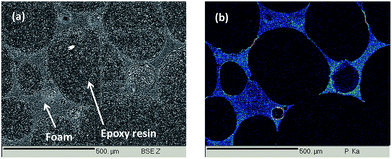
At magnification ×30, the open-cell structure is similar to that observed for the virgin foam structure. However, at higher magnifications, a thin homogeneous coating is observed on and around the PU cells. To confirm this homogeneous coating, phosphorus X-ray mapping of a cross-section of the foam was carried out using EPMA and is presented in Fig. 8. To facilitate the cross-section preparation, cells were filled in with an epoxy resin. On the Back Scattering Electron (BSE) picture presented in Fig. 8a, the light grey parts correspond to the coated PU structure whereas dark grey parts correspond to the embedding epoxy resin.
On Fig. 8b it is clearly visible that the phosphorus containing coating is homogeneously spread everywhere in and on the whole polyurethane foam structure after sonication. It so confirms our previous assumption that the foam is homogeneously coated and that the coating is homogeneous on the whole foam, both inside and on the surface of the PU foam. It also corroborates the hypothesis that the graft-polymerized precursor is strongly anchored to the polyurethane foam.
In order to try to identify the species present at the foam surface, 31P solid state NMR was carried out on both non rinsed and rinsed coated PU foams.
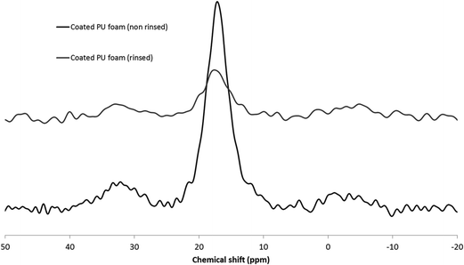
The spectra obtained for the coated PU foams before and after rinsing are presented in Fig. 9.
When DEVP is plasma graft-polymerized on the PU foam, an intense and broad peak at 17 ppm is observed, corresponding to phosphonate units.27 The smaller and large peaks around 33 ppm and −2 ppm can be attributed to phosphonate derivatives28 resulting from the plasma gas action (chain scission, recombination, etc.). The peak at 17 ppm characteristic of phosphonates still exists after rinsing, with lower intensity as well as the two other peaks. It demonstrates that the phosphorus containing species still remain on the PU foam after rinsing.
Cold plasma is a very efficient process to graft-polymerize monomers containing vinyl groups by reaction between hydrophilic functions present at the surface of a sample with the vinyl group of a monomer through covalent bonding. These hydrophilic functions can be introduced through an activation treatment as it was previously shown in various works.19,29,30 Such activation will create hydroxide, peroxide and hydroperoxide groups on the surface of the sample. This is in good agreement with the results obtained in this work: when no activation was done before coating, the DEVP coated foam did not show any FR properties after rinsing.
A simplified PU foam activation mechanism is shown in Fig. 10.
Moreover, it was shown that when no crosslinker is added, the weight gain is very low and consequently no FR effect is observed (Fig. 4). It could then reasonably be assumed that the crosslinker reacts with the hydroperoxide functions of the activated PU and that this crosslinker grafting favors further immobilization of the DEVP precursor in the plasma by radical reaction.31 To try to go further in the mechanism of formation of the deposit, XPS analyses were carried out on two representative samples: virgin PUF and coated PUF after rinsing.
The atomic percentages obtained for both samples are summarized in Table 1.
| C1s (%) | O1s (%) | N1s (%) | P2p (%) | O1s/C1s (%) | P2p/C1s (%) | |
|---|---|---|---|---|---|---|
| Neat PUF | 75.3 | 22.2 | 2.5 | 0.0 | 29.5 | 0.0 |
| Coated PUF (after rinsing) | 72.0 | 26.8 | 0.1 | 1.1 | 37.2 | 1.5 |
Looking at the phosphorus percentage, it is clear that some phosphorus is still present on the PUF surface after rinsing. It confirms the results obtained by EPMA (Fig. 8). Considering the nitrogen content, the polyurethane surface is not detected anymore since a negligible amount of nitrogen is observed. It must be reminded that with the XPS technique, only the extreme surface (10 nm depth) is analyzed. Thus, when a new layer is present on the foam, the underlying layer cannot be detected.
The decompositions of C1s peaks obtained for both materials were then carried out. The percentage of each bond was calculated and results are shown in Table 2.
| C1s | ||
|---|---|---|
| Bonds | eV | % |
| Virgin PU foam | ||
C![[double bond, length as m-dash]](https://www.rsc.org/images/entities/char_e001.gif) C C |
283.6 | 35.35 |
| C–C | 285 | 53.73 |
| C–O/C–N | 285.7 | 6.75 |
O![[double bond, length as m-dash]](https://www.rsc.org/images/entities/char_e001.gif) C(–N)–O C(–N)–O |
287.6 | 4.17 |
![[thin space (1/6-em)]](https://www.rsc.org/images/entities/char_2009.gif) |
||
| Coated and rinsed PU | ||
| C–C | 285 | 47.84 |
| C–O/C–N | 286.2 | 29.28 |
| O–C–O | 287 | 11.66 |
| C–P | 288.8 | 11.22 |
On the coated and rinsed PU foam, no C![[double bond, length as m-dash]](https://www.rsc.org/images/entities/char_e001.gif) C bonds are detected. The absence of C
C bonds are detected. The absence of C![[double bond, length as m-dash]](https://www.rsc.org/images/entities/char_e001.gif) C bonds confirms again that the PU surface is not detected by XPS analysis and it can thus be assumed that (i) all non-reacted precursor has been removed from foam surface and that (ii) only reacted crosslinker is present. Moreover, a large amount of C–P (11%) bonds are identified, confirming the presence at the surface of the DEVP derivatives previously observed by 31P NMR.
C bonds confirms again that the PU surface is not detected by XPS analysis and it can thus be assumed that (i) all non-reacted precursor has been removed from foam surface and that (ii) only reacted crosslinker is present. Moreover, a large amount of C–P (11%) bonds are identified, confirming the presence at the surface of the DEVP derivatives previously observed by 31P NMR.
Considering NMR and XPS results, the following mechanism of action can be suggested: the crosslinker could covalently bind the PUF, and then the vinyl group of DEVP could react with the radical formed on the crosslinker (Fig. 11).
However, this figure gives only a hint of the principle mechanisms, and the last figure does not completely correspond to the coating obtained at the end of the process, as the C![[double bond, length as m-dash]](https://www.rsc.org/images/entities/char_e001.gif) C bonds react in the plasma, and the residual radicals tend to react with oxygen from air after the process.
C bonds react in the plasma, and the residual radicals tend to react with oxygen from air after the process.
It is possible that some phosphonates also directly graft onto the PUF, but as no FR effect is observed when no crosslinker is added, the configuration presented in Fig. 11 is more likely.
As observed in the previous parts, the presence of only 6% weight uptake is sufficient to obtain a clear fire retardant effect. The next step of this study thus consists in understanding the flame retardant mode of action of DEVP based coating on both sonicated and non-sonicated coated PU foams.
First, on both non sonicated and sonicated samples, fire performances were evaluated using the UL94 horizontal burning test, applying a flame for 10 s but also for 60 s.
The results are summarized in the Table 3.
| PU foam | DEVP-coated foam-no rinsing | DEVP-coated foam-rinsed | ||||
|---|---|---|---|---|---|---|
| Time to exposure to flame | 10 s | 60 s | 10 s | 60 s | 10 s | 60 s |
| Dripping | Yes, cotton ignition | Yes, cotton ignition | No | No | No | No |
| Time of combustion after removing of the flame | 1 s (dripping) | 1 s (dripping) | 0 s | 0 s | 4 s (on a 5 mm2 zone) | 5 s (on a 5 mm2 zone) |
| Charring length while PU foam in contact with the flame | NC | NC | 5 mm | 1.5 cm | 2 cm | 2 cm |
| Self-extinguishment when flame out | Yes (due to dripping) | Yes (due to dripping) | NC | NC | Yes | Yes |
Pictures of the coated samples after 10 s and 60 s exposure to the flame are presented in Fig. 12.
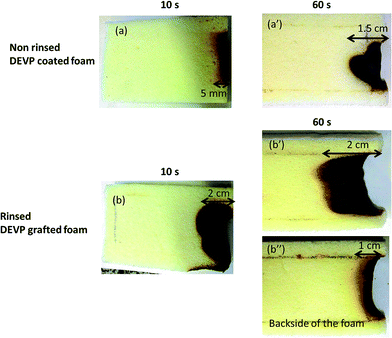 | ||
| Fig. 12 Numerical pictures of the samples obtained after 10 s and 60 s exposure to horizontal burning test of the non-washed coated foam (a and a′) and of the washed coated foam (b, b′ and b′′). | ||
The non-sonicated coated PUF does not ignite or drip when put in contact with the Bunsen burner, only the part in contact with the flame becomes black on a 5 mm wide zone when the sample is exposed for 10 s to the flame and on a 1.5 cm wide zone when it is exposed to the flame for 60 s. In both cases, when the flame is removed, no flame or ignited part is visible and charring phenomenon stops immediately.
The sonicated coated PUF ignites, and flame spreads on about 2 cm whatever the time of exposure (10 s or 60 s). When the char is formed the flame remains on the charred part and does not spread on the rest of the foam. When the burner is removed, small flames remain on tiny zones (about 5 mm2) of the charred part, which self-extinguish very rapidly and no additional charring is observed.
In order to understand the fire retardant mechanism of action, thermal decompositions of virgin PUF and coated PUF (before and after sonication) were first studied by TGA. TG and DTG curves as well as corresponding data of virgin and coated PUF (before and after sonication) are presented respectively in Fig. 13a and b and Table 4.
 | ||
| Fig. 13 (a) TGA curves and (b) DTG curves of pure PUF, pure DEVP, non-rinsed DEVP coated foam and rinsed DEVP coated foam. | ||
| Sample | T5%* (°C) | Tmax** 1 (°C) | Tmax 2 (°C) | Tmax 3 (°C) | Tmax 4 (°C) | Char residue 600 °C (wt%) | Char residue 800 °C (wt%) |
|---|---|---|---|---|---|---|---|
| DEVP | 64 | 111 | 0 | 0 | |||
| Neat PU foam | 246 | 259 | 290 | 394 | 3.8 | 2.4 | |
| Coated PUF (no sonication) | 113 | 113 | 270 | 311 | 398 | 4 | 3 |
| Coated PU foam (sonication) | 242 | 118 | 270 | 311 | 394 | 7 | 3.8 |
The thermal decomposition of virgin PUF and the formation of its various decomposition products are well described in the literature.32,33 The first stage of decomposition leads to depolymerization reactions which are characteristic of urethane and substituted urea bond cleavage, to form isocyanate, polyol, primary or secondary amine. Surprisingly it is observed that both treated foams start to degrade at lower temperature as compared to that of virgin PUF. This might also be attributed to the catalytic effect of phosphonic acid derivatives formed during the thermal decomposition of phosphonates, thus accelerating the depolymerization of the urethane moiety.34,35 The following stages of decomposition are mainly due to subsequent degradation of the remaining polyol chains and dimerization and trimerization of isocyanates.36,37
TG data of the coated PUF before sonication indicate a degradation step in the range of 100–200 °C compared to the virgin PUF and thus a higher weight loss (see T5% in Table 4). This could be attributed to the presence of non-coated DEVP, which is completely degraded at 123 °C. The rinsed coated PUF also shows a higher weight loss in the range of 100–200 °C, but much lower than for the non-rinsed foam.
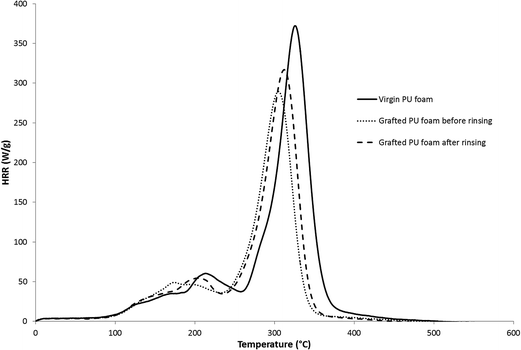
The different foams were then evaluated by microscale combustion calorimetry (MCC)38 (Fig. 14). The data are summarized in Table 5.
| pHRR (W g−1) | |
|---|---|
| Virgin PU | 375 ± 5 |
| Coated PU foam before rinsing | 289 ± 6 |
| Coated PU foam after rinsing | 312 ± 3 |
In MCC technique, the gases released during the pyrolysis are evacuated into an oven at 900 °C containing a 80/20 N2/O2 mixture. In these conditions, a total combustion of these gases takes place. The MCC calculates the heat release rate by measuring the consumption of oxygen.
The virgin PU foam exhibits a maximum pHRR of 375 W g−1 and a corresponding decomposition temperature of 325 °C. The combustion of flexible polyurethane foams is known to be a two main steps process. The first step corresponds to the melting and degradation of the foam into a tar and the second step to the combustion of the tar previously produced.33,39 These two degradation steps lead to two distinct peaks of rate of heat release.
The graft-polymerized sample before rinsing shows a decrease of pHRR of about 23% and a shift to lower temperatures in comparison with the reference PU foam, which is explained by the fact that phosphonate containing flame retardants catalyze the char formation by their decomposition in phosphonic acid.40–42 The sample after sonication presents a decrease of pHRR of about 17%, which is slightly lower than the sample before sonication, but which can be also related to the difference in term of weight uptake (14% before sonication against 6% after sonication).
These microcalorimeter results can be explained by two hypotheses: (i) the phosphonate based coatings partly flame retard the foam by a gas phase mechanism or (ii) the FR mechanism is a condensed phase mechanism with only a small amount of gases released. To confirm one of these hypotheses, MCC curves were overlapped with TGA curves. For the three formulations, the second combustion step observed by MCC around 300 °C corresponds to the third main degradation step observed by TGA (Fig. 13). Looking at this third step, no particular difference in term of weight loss between the three samples is observed, whereas a decrease of HRR is observed at the same temperature using MCC. If the FR mechanism was only a condensed phase mechanism, the degradation rate would have been different between the samples. This proves that this decrease of HRR is at least partly driven by a gas phase mechanism.
Taking into account these results and the results obtained in the previous section, one hypothesis is thus that the non-grafted DEVP present on non-sonicated coated PUF may get vaporized earlier for possible flame-poisoning or gas phase actions at low temperature (100–150 °C), while the grafted DEVP might act mainly in the condensed phase at higher temperature.
To distinguish both condensed or gas phase action phenomena and understand the FR mechanism of action of DEVP, further analyses were carried out.
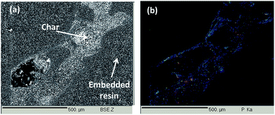
The char obtained after flame spread test of the rinsed DEVP-coated sample was analyzed by phosphorus X-ray mapping in cross-section using EPMA. Again, the char was embedded in an epoxy resin to facilitate the cross-section preparation (Fig. 15).
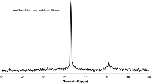
Phosphorus is still present after burning and is homogeneously dispatched in the char. In order to identify the phosphorus species, a 31P solid state NMR was then carried out on the char residue (Fig. 16).
One very thin peak is observed at 17 ppm, same chemical shift as the one observed before burning, characteristic of phosphonates (cf. Fig. 9). However, based on literature review, this chemical shift also corresponds to well crystallized phosphonic acid derivatives.43,44 The attribution of this peak to phosphonic acid is in accordance with the literature, thermal decomposition of phosphonates leading to the formation of phosphonic acid.45 The other small peak at −1 ppm corresponds to orthophosphates, which is also in accordance with the mechanism of degradation of phosphonates.
As phosphorus species, and in particular phosphonic acid, are still present in the char after burning, it is possible to conclude that, after sonication the phosphorus grafted species act, at least partly, as FR in the condensed phase.
The gaseous degradation products were first investigated during thermal degradation by FTIR analyses (TGA-FTIR). The virgin PU foam decomposes between 200 and 450 °C when heated and produces numerous compounds containing for example C![[double bond, length as m-dash]](https://www.rsc.org/images/entities/char_e001.gif) O and NCO functions due to depolymerization and chain scissions. Some of the gases released during degradation of virgin PU foam, such as CO2 (2200–2400 cm−1), CO (2100–2200 cm−1), or other compounds including NCO (2275 cm−1), RC
O and NCO functions due to depolymerization and chain scissions. Some of the gases released during degradation of virgin PU foam, such as CO2 (2200–2400 cm−1), CO (2100–2200 cm−1), or other compounds including NCO (2275 cm−1), RC![[double bond, length as m-dash]](https://www.rsc.org/images/entities/char_e001.gif) O (1720–1740 cm−1) or aliphatic groups' bands (2700–3200 cm−1) can be identified on FTIR spectra of neat PU foam and coated PU foams before and after rinsing (not presented in the paper).46–48 However, as already mentioned according to TGA data, the products released by the grafted DEVP appear at lower temperatures than those of the virgin PUF.
O (1720–1740 cm−1) or aliphatic groups' bands (2700–3200 cm−1) can be identified on FTIR spectra of neat PU foam and coated PU foams before and after rinsing (not presented in the paper).46–48 However, as already mentioned according to TGA data, the products released by the grafted DEVP appear at lower temperatures than those of the virgin PUF.
The Fig. 17 presents a comparison of the FTIR spectra of pure DEVP collected at T = 20 °C with the one of the gases collected at T = 135 °C during the TGA-FTIR analyses. Spectra of the degradation gases of DEVP-coated PUF before and after rinsing at T = 135 °C are also compared. The peaks obtained for DEVP at 20 °C and DEVP at 135 °C are relatively similar. The same peaks are retrieved in the case of the PU coated foams before rinsing. It thus confirms our previous assumption: the first step of degradation corresponds to the release of non-grafted and non-polymerized DEVP. The absorbance is however much lower and the peaks are hardly detected when the foam has been rinsed, confirming that most of the residual non-grafted DEVP has been removed during rinsing.
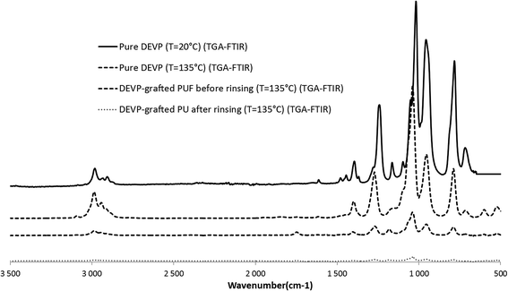 | ||
| Fig. 17 Comparison between FTIR-ATR of pure DEVP at 20 °C and FTIR (obtained by TGA-FTIR) of DEVP and DEVP-coated PUF before and after rinsing at T = 135 °C. | ||
The majority of non-grafted DEVP is thus vaporized at low temperature (100–150 °C) for flame-poisoning or gas phase action.37 This is in accordance with the behavior of the non-rinsed PUF during flame spread test: the sample does not ignite, which is characteristic of a gas phase mechanism.
This gas phase mode of action of non-grafted DEVP is confirmed by Liang et al. who show by mass spectrometry analyses37 and more recently by vacuum ultraviolet ionization49 that in the case of allyl-substituted phosphonates the formation of the important PO˙ fragment during the foam degradation is favored. These radicals play an important role in the flame inhibition cycle in which the H˙ and OH˙ radicals (formed from the decomposition of the substrate) are readily scavenged. This reduces the fuel (H˙ and OH˙ radicals) available to propagate the flame, and further results in the decrease of heat production.
At higher temperatures, no differences in the FTIR spectra (results not presented) between neat PU foam and non-rinsed and rinsed coated PU foams are observed.
It seems that no phosphorus containing species other than those from DEVP precursor are identified in the FTIR spectrum of the rinsed PU foam. Thus it is likely that the remaining amount of phosphorus containing species is retained in the residue, exhibiting subsequently mainly condensed phase activity.
To confirm this, pyrolysis-GC/MS was carried out on the same samples. The chromatograms are presented on Fig. 18.
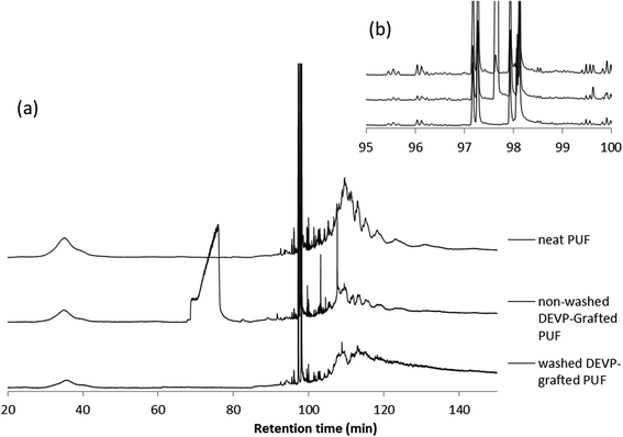 | ||
| Fig. 18 (a) py-GC/MS of PU foam and DEVP-coated PU foam (rinsed or not), (b) zoom on the 95–100 min region. | ||
In the chromatogram of neat PU foam, three parts are identified. The broad band between 30 and 42 min corresponds to small aliphatic fragments probably produced by the decomposition of the polyol. The fine peaks between 97 and 99 min correspond to the isocyanate units obtained by a depolymerization processes. Over 100 min, a broad band containing some undefined structures would correspond to various PU fragments (mixture of aromatic structures and aliphatic structures).
The chromatogram of non-rinsed DEVP-coated PU foam reveals the same bands as for neat PU foam except one between 70 and 80 min corresponding to free DEVP, and one at 97.6 min characteristic of the crosslinker (Fig. 18b). Small peaks around 105 and 110 min also correspond to structures derived from the crosslinker.
Finally, the chromatogram of rinsed DEVP-coated PU foam evidences the absence of DEVP as the characteristic band previously observed disappears. The band from 100 to 130 min is slightly different from that of neat PU foam. The band is thinner and more resolved and the earlier retention time suggests a possible shift to shorter mass elements and thus a change in the degradation pathway of PU foam. py-GC/MS analysis allowed showing the degradation of rinsed DEVP-coated PU foam may be slightly modified, and all the volatile DEVP has been removed, which means that if any phosphorus was observed, the compound would be grafted at the surface.
As phosphonic acid is depicted by 31P solid state NMR in the char of the rinsed coated PU foam (Fig. 16), this proves that the grafted phosphorus containing species mainly play a FR role in the condensed phase.
Discussion
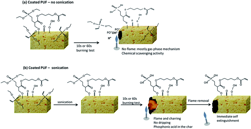
The analyses of the condensed and gas phase of the non-sonicated and sonicated coated PU foams show two different FR modes of action, represented in the Fig. 19.When the foam is plasma treated and tested to UL94 horizontal test without any sonication (Fig. 19a), its surface is covered with (i) non grafted DEVP and (ii) grafted DEVP, with a total weight gain of about 14%. Under the action of the flame, non-grafted DEVP is vaporized at low temperature (100–150 °C), as it was proven by TGA-FTIR and py-GC/MS. The PO˙ radicals formed play an important role in the flame inhibition cycle in which the H˙ and OH˙ radicals (formed from the decomposition of the substrate) are readily scavenged. This explains why during the 10 s or 60 s burning test no flame is produced.
The FR mechanism is different after sonication (Fig. 19b). Indeed, after sonication, only grafted DEVP (as it was proven by XPS) is present at the PUF surface, and the total weight gain is 6%. When the sonicated sample is submitted to the horizontal burning test, a flame appears, but charring occurs very rapidly, without any dripping. Analyses of the char show the presence of phosphonic acid (degradation product of phosphonates) and an homogeneous repartition of phosphorus in the char. In that case, the most probable FR mechanism of action is a condensed phase mechanism: the presence of phosphorus promotes the char formation, which protects the underlying PU foam from burning. When the flame is removed, the flame thus self-extinguishes.
Conclusion
Flexible open-cell polyurethane foams were coated, using cold plasma induced graft polymerization treatments, with DEVP precursors. These PUF were then sonicated and their weight uptake and behavior to UL-94 horizontal test were investigated. The results obtained show that in order to obtain a sufficient weight gain after sonication it is necessary (i) to use a crosslinker, as DEVP mainly reacts with this crosslinker and (ii) to activate the PU foam before graft-polymerization to promote further reaction with the crosslinker. One coating system reaches 14% grafting rate before sonication and 6% after sonication. Both these coatings prevent foam dripping during horizontal burning test and promote charring and self-extinguishment after flame removal.Microscopic analyses after sonication show that the coating is homogeneously spread everywhere in and on the whole polyurethane foam structure. Considering solid state NMR and XPS results, the following mechanism of action can be suggested: the crosslinker reacts with the PUF, and simultaneously the phosphorus containing species (i.e. mainly phosphonates) covalently react with the crosslinker, which explains the good resistance to sonication.
The condensed and gas phase analyses proved that before rinsing, non-reacted DEVP precursors mainly act in the gas phase, preventing ignition, whereas after rinsing the covalently grafted phosphorus containing species mainly act in the condensed phase to form phosphonic acid which will promote charring and thus will limit dripping and flame spread.
Conflict of interest
The authors declare no competing financial interest.Acknowledgements
The authors would like to thank Bertrand Revel and Bertrand Doumert for NMR analyses, Dr Arnaud Beaurain for XPS analyses and SAIRA SEATS SAS for providing the polyurethane foam samples.References
- R. H. Krämer, M. Zammarano, G. T. Linteris, U. W. Gedde and J. W. Gilman, Polym. Degrad. Stab., 2010, 95, 1115–1122 CrossRef PubMed.
- I. Watanabe and S. I. Sakai, Environ. Int., 2003, 29, 665–682 CrossRef CAS.
- V. Babrauskas, A. Blum, R. Daley and L. Birnbaum, 10th International Symposium on Fire Safety Science, College Park, MD, 2011.
- California state assembly, Assembly Bill 302, 2003.
- EUROPA, Official Journal of the European Union, 2003, Directive 2003/11/EC, OJ L42/45.
- R. Renner, Environ. Sci. Technol., 2004, 38(24), 481A CrossRef CAS.
- S. V. Levchik and E. D. Weil, Polym. Int., 2004, 53, 1585–1610 CrossRef CAS PubMed.
- M. Modesti and A. Lorenzetti, Polym. Degrad. Stab., 2002, 78, 167–173 CrossRef CAS.
- H. Singh and A. K. Jain, J. Appl. Polym. Sci., 2009, 111, 1115–1143 CrossRef CAS PubMed.
- D. K. Chattopadhyay and D. C. Webster, Prog. Polym. Sci., 2009, 34, 1068–1133 CrossRef CAS PubMed.
- J. Jang, H. Chung, M. Kim and H. Sung, Polym. Test., 2000, 19, 269–279 CrossRef CAS.
- M. Demirel, V. Pamuk and N. Dilsiz, J. Appl. Polym. Sci., 2010, 115, 2550–2555 CrossRef CAS PubMed.
- Y. S. Kim, R. Davis, A. A. Cain and J. C. Grunlan, Polymer, 2011, 52, 2847–2855 CrossRef CAS PubMed.
- G. Laufer, C. Kirkland, A. B. Morgan and J. C. Grunlan, ACS Macro Lett., 2013, 2, 361–365 CrossRef CAS.
- R. Davis, Y. C. Li, M. Gervasio, J. Luu and Y. S. Kim, ACS Appl. Mater. Interfaces, 2015, 7, 6082–6092 CAS.
- H. Pan, W. Wang, Y. Pan, L. Song, Y. Hu and K. M. Liew, ACS Appl. Mater. Interfaces, 2015, 7, 101–111 CAS.
- Y. H. Yang, Y. C. Li, J. Shields and R. D. Davis, J. Appl. Polym. Sci., 2015, 132(14), 41767 Search PubMed.
- M. J. Tsafack and J. Levalois-Grützmacher, Surf. Coat. Technol., 2007, 201, 5789–5795 CrossRef CAS PubMed.
- M. J. Tsafack and J. Levalois-Grützmacher, Surf. Coat. Technol., 2006, 201, 2599–2610 CrossRef CAS PubMed.
- B. Edwards, A. El-Shafei, P. Hauser and P. Malshe, Surf. Coat. Technol., 2012, 209, 73–79 CrossRef CAS PubMed.
- S. Duquesne, J. Lefebvre, G. Seeley, G. Camino, R. Delobel and M. Le Bras, Polym. Degrad. Stab., 2004, 85, 883–892 CrossRef CAS PubMed.
- C. Q. Wang, F. Y. Ge, J. Sun and Z. S. Cai, J. Appl. Polym. Sci., 2013, 130(2), 916–926 CrossRef CAS PubMed.
- R. Liepins, J. R. Surles, N. Morosoff, V. Stannett, J. J. Duffy and F. H. Day, J. Appl. Polym. Sci., 1978, 22, 2403–2414 CrossRef CAS PubMed.
- R. Liepins, J. R. Surles, N. Morosoff, V. T. Stannett and R. H. Barker, Radiat. Phys. Chem., 1977, 9, 465–474 CrossRef CAS.
- T. Sato, M. Hasegawa, M. Seno and T. Hirano, J. Appl. Polym. Sci., 2008, 109, 3746–3752 CrossRef CAS PubMed.
- M. J. Tsafack and J. Levalois-Grützmacher, Surf. Coat. Technol., 2006, 200, 3503–3510 CrossRef CAS PubMed.
- J. Köhler, H. Keul and M. Möller, Chem. Commun., 2011, 47, 8148–8150 RSC.
- X. Yu, N. P. Price, B. S. Evans and W. W. Metcalf, J. Bacteriol., 2014, 196, 1768–1779 CrossRef PubMed.
- S. Degoutin, M. Jimenez, M. Casetta, S. Bellayer, F. Chai, N. Blanchemain, C. Neut, I. Kacem, M. Traisnel and B. Martel, Biomed. Mater., 2012, 7, 035001 CrossRef CAS PubMed.
- M. Vandenbossche, M. Jimenez, M. Casetta, S. Bellayer, A. Beaurain, S. Bourbigot and M. Traisnel, React. Funct. Polym., 2013, 73, 53–59 CrossRef CAS PubMed.
- H.-S. Choi, Y.-S. Kim, Y. Zhang, S. Tang, S.-W. Myung and B.-C. Shin, Surf. Coat. Technol., 2004, 182, 55–64 CrossRef CAS.
- M. Ravey and E. M. Pearce, J. Appl. Polym. Sci., 1997, 63, 47–74 CrossRef CAS.
- J. Lefebvre, B. Bastin, M. le Bras, S. Duquesne, R. Paleja and R. Delobel, Polym. Degrad. Stab., 2005, 88, 28–34 CrossRef CAS PubMed.
- T. Mao, Z. Guan, H. Luo, Z. Liang, X. Wang, Z. Jia and L. Wang, Modification of terylene fabric by homogeneous discharge in air at atmospheric pressure, 2007 Annual Report – Conference on Electrical Insulation and Dielectric Phenomena, CEIDP, Vancouver, BC, 2007, pp. 124–127 Search PubMed.
- S. Gaan, G. Sun, K. Hutches and M. H. Engelhard, Polym. Degrad. Stab., 2008, 93, 99–108 CrossRef CAS PubMed.
- A. W. Benbow and C. F. Cullis, Combust. Flame, 1975, 24, 217–230 CrossRef CAS.
- S. Liang, M. Neisius, H. Mispreuve, R. Naescher and S. Gaan, Polym. Degrad. Stab., 2012, 97, 2428–2440 CrossRef CAS PubMed.
- R. E. Lyon and R. N. Walters, J. Anal. Appl. Pyrolysis, 2004, 71, 27–46 CrossRef CAS.
- J. Lefebvre, B. Bastin, M. le Bras, S. Duquesne, C. Ritter, R. Paleja and F. Poutch, Polym. Test., 2004, 23, 281–290 CrossRef CAS PubMed.
- G. Laufer, C. Kirkland, A. B. Morgan and J. C. Grunlan, Biomacromolecules, 2012, 13, 2843–2848 CrossRef CAS PubMed.
- Y.-C. Li, S. Mannen, A. B. Morgan, S. Chang, Y.-H. Yang, B. Condon and J. C. Grunlan, Adv. Mater., 2011, 23, 3926–3931 CrossRef CAS PubMed.
- S. Duquesne, M. Le Bras, C. Jama, E. D. Weil and L. Gengembre, Polym. Degrad. Stab., 2002, 77, 203–211 CrossRef CAS.
- R. Tayouo, G. David, B. Améduri, J. Rozière and S. Roualdès, Macromolecules, 2010, 43, 5269–5276 CrossRef CAS.
- F. Laoutid, L. Bonnaud, M. Alexandre, J. M. Lopez-Cuesta and P. Dubois, Mater. Sci. Eng., R, 2009, 63, 100–125 CrossRef PubMed.
- K. Troev, in Chemistry and application of H-phosphonate, Elsevier, 2006, pp. 5–19 Search PubMed.
- U. Braun, A. I. Balabanovich, B. Schartel, U. Knoll, J. Artner, M. Ciesielski, M. Döring, R. Perez, J. K. W. Sandler, V. Altstädt, T. Hoffmann and D. Pospiech, Polymer, 2006, 47, 8495–8508 CrossRef CAS PubMed.
- K. Wu, Y. Hu, H. L. L. Song and Z. Wang, Ind. Eng. Chem. Res., 2009, 48, 3150–3157 CrossRef CAS.
- K. Wu, L. Song, Y. Hu, H. Lu, B. K. Kandola and E. Kandare, Prog. Org. Coat., 2009, 65, 490–497 CrossRef CAS PubMed.
- S. Liang, P. Hemberger, N. M. Neisius, A. Bodi, H. Grützmacher, J. Levalois-Grützmacher and S. Gaan, Chem.–Eur. J., 2015, 21, 1073–1080 CrossRef CAS PubMed.
| This journal is © The Royal Society of Chemistry 2015 |

