An unusual spherulite morphology induced by nano-fillers from a concentrated cellulose/ionic liquid solution

Meichun Dingab, Jian Yu*a, Jiasong Hea and Jun Zhang*a
aBeijing National Laboratory for Molecular Sciences, CAS Key Laboratory of Engineering Plastics, Institute of Chemistry, Chinese Academy of Sciences (CAS), Beijing, 100190, China. E-mail: yuj@iccas.ac.cn; jzhang@iccas.ac.cn
bUniversity of Chinese Academy of Sciences, Beijing, 100039, China

Received 15th April 2015 , Accepted 8th May 2015

First published on 8th May 2015


Abstract

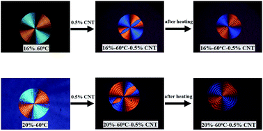
An unusual spherulite morphology consisting of an eye-like region surrounded by a normal region was found in concentrated cellulose solutions in the ionic liquid AmimCl, especially in the presence of 0.5 wt% MWCNTs. In comparison with the normal region, the eye-like region had a different growth rate and different morphology, such as birefringence and band spacing, although both regions had similar crystalline modification and microstructure. On heating, the regions with an initial positive birefringence transformed to more thermodynamically stable negative ones without influencing the band spacing, and the change was irreversible upon cooling.


Spherulites are a kind of important morphological form in the crystal structure of semicrystalline polymers. The microstructure and size of the spherulites have a great influence on the performance of polymers.1–3 For most linear semicrystalline polymers, spherulites can be formed through melt or solution crystallization. The formation and morphology of spherulites depend on many factors, such as crystallization temperature, sample thickness, polymer molar mass and additives. The influence of additives, especially nano-fillers, on polymer crystallization has attracted increasing attention during the past few decades. It can change the spherulitic size, morphology, and growth rate, consequently modulate the physical and mechanical properties of the polymer materials.4–9

Cellulose is the most abundant natural polymer on the earth, well-known for its renewable, biodegradable, and biocompatible properties. Nowadays, various cellulose-based materials, including regenerated cellulose materials (fibers and films) and cellulose derivatives (esters and ethers), are widely applied. However, cellulose cannot be melted due to its strong intramolecular and intermolecular hydrogen bonding interaction. So far, spherulites of cellulose were observed only in a very few cellulose solutions, the first report was cellulose-N-methylmorpholine-N-oxide (NMMO) system. However, whether the spherulites were formed from cellulose or NMMO is still under dispute.10–13 Recently, room temperature ionic liquids have received considerable attentions for cellulose dissolution due to their excellent dissolution ability,14–17 which provides a new and robust platform for both cellulose science in chemistry and physics and cellulose technology in processing and functionalization.18,19 In our previous study, ring-banded spherulites of cellulose were obtained from concentrated microcrystalline cellulose/1-allyl-3-methylimidazolium chloride (MCC/AmimCl) solutions,20 of which the size and morphology are associated with the crystallization temperature and the solution concentration. It would provide not only the new insight into cellulose crystallization, but also new opportunities to manipulate the properties of regenerated cellulose materials by controlling the crystallization conditions.

In this letter, an unusual ring-banded spherulite of cellulose, which contained two different regions, i.e., an eye-like region and a normal region, was observed clearly by adding 0.5 wt% multi-walled carbon nanotubes (MWCNTs) in MCC/AmimCl solution. The polarized optical microscopy (POM) images of these spherulites are shown in Fig. 1. To the best of our knowledge, this unusual morphology has never been observed in solution crystallization, while it has been reported only in melt-crystallized poly[(R)-3-hydroxyvalerate)] (PHV) at appropriate temperatures.21


image file: c5ra06740e-f1.tif
Fig. 1 POM images of cellulose spherulites crystallized from 16 wt% and 20 wt% MCC/AmimCl solution at 40 °C and 60 °C (16 wt%-40 °C (a), 20 wt%-40 °C (b), 16 wt%-60 °C (c), and 20 wt%-60 °C (d)); and with 0.5 wt% MWCNTs (16 wt%-40 °C-0.5% CNT (e), 20 wt%-40 °C-0.5% CNT (f), 16 wt%-60 °C-0.5% CNT (g), and 20 wt%-60 °C-0.5% CNT (h)).

The spherulites were obtained by keeping MCC/AmimCl solutions with high concentrations (16 and 20 wt%) and nano-fillers at certain temperatures (40 and 60 °C) and a relative humidity of 25% for 6 days. It can be seen from Fig. 1 that the eye-like region grew from the center of spherulites, which was surrounded by the normal region. Some of them were symmetrical (Fig. 1e and f), while the others were asymmetric (Fig. 1g and h). Moreover, the direction of the eye-like region changed when the cellulose spherulite was rotated in the plane (Fig. S1), indicating the eye-like region was a physical entity in the spherulite with a fixed position. And it displayed the birefringence opposite to that of the surrounding normal region independent of its direction, i.e., the eye-like region with positive birefringence was surrounded by the normal region with negative birefringence, and vice versa. And the band spacing was also different in these two regions. As shown in both Fig. 1g and h, the regions with negative birefringence had a bit smaller band spacing than those with positive birefringence. The results of the micro-Raman spectra (Fig. S2) and atomic force microscopy (Fig. S3) confirmed that these two regions have no significant difference in microstructure and crystalline modification. By comparison, the eye-like region was hardly observed in spherulites obtained from pure cellulose solutions (Fig. 1a–d), and few spherulites can be found to have the eye-like region in the samples containing less contents of MWCNTs (Fig. S4). The similar spherulite morphology was also observed for concentrated MCC/AmimCl solution containing 0.5 wt% nanoclay and graphene oxide (GO)22 (Fig. 2). Therefore, it is clear that the eye-like morphology was formed in the crystallization of cellulose from AmimCl solutions, especially in the presence of proper amount of nano-fillers.


image file: c5ra06740e-f2.tif
Fig. 2 POM images of cellulose spherulites crystallized from 20 wt% MCC/AmimCl solution at 60 °C with different fillers of 0.5 wt% nanoclay (a), and 0.5 wt% GO (b).

As indicated in the literature,21 the lamellae in the eye-like region have different growth axis from those in the normal region, and the spherulites can grow in both axes simultaneously. In the present study, due to the relatively large aspect ratio of the nano-fillers having fiber-like (MWCNTs) and sheet-like (nanoclay and GO) shapes, the nano-fillers and the baby lamellae would preferentially adopt an orientation parallel to the substrate in a thin film. Subsequently, the baby lamellae can grow along both axes without confinement to the film thickness. As revealed from POM observation, two regions developed from the center of the spherulite simultaneously. However, one region grew along the radical direction with a lower rate than the other one, and surrounded by the latter to form eye-like shape eventually. Fig. 3 shows that the eye-like region stopped growing after 5 days, and the size of normal region increased slowly and continuously. It also shows that the growth rate of spherulites reduced in the presence of 0.5 wt% MWCNTs, compared to spherulites obtained from pure MCC/AmimCl solution, due to the nano-fillers blocking the movement of cellulose chains.


image file: c5ra06740e-f3.tif
Fig. 3 Growth profiles of cellulose spherulites crystallized from 20 wt% MCC/AmimCl solution at 60 °C.

It is worth to note that the birefringence of these spherulites changed after heating. The heating process of two kinds of typical cellulose spherulites was followed by POM observation from 30 to 100 °C at a heating rate of 10 °C min−1 (Animations S1 and S2), and the images at different temperatures were shown in Fig. 4. The initial spherulites in sample 16%-60 °C-0.5% CNT (Fig. 4a) have the eye-like region with positive birefringence and the normal region with negative birefringence, while in the sample 20%-60 °C-0.5% CNT (Fig. 4d) have the negative eye-like region and the positive normal region. On heating, all the regions with positive birefringence transformed to negative regions, hence spherulites with complete negative birefringence were obtained in both cases.


image file: c5ra06740e-f4.tif
Fig. 4 POM images of cellulose spherulites during heating. Sample 16%-60 °C-0.5% CNT at 30 °C (a), 70 °C (b), and 80 °C (c); sample 20%-60 °C-0.5% CNT at 30 °C (d), 82 °C (e), and 90 °C (f).

It was shown in Fig. 4 that the transition temperature of the sample 16%-60 °C-0.5% CNT (Fig. 4a–c) was lower than that of the sample 20%-60 °C-0.5% CNT (Fig. 4d–f). At the same time, the band spacing remained unaltered as the birefringence varied. Therefore, an eye-like region can also be discerned, which had same birefringence with the surrounding region. More importantly, the changes were irreversible when the sample cooled down at 10 °C min−1. The transformation of birefringence was also observed for cellulose spherulites obtained in the presence of nanoclay and GO. Therefore, the negative region in cellulose spherulite was thermodynamically stable compared with the positive one, while the positive normal region was kinetically favorable under high temperature (60 °C), high concentration (20 wt%), and a relatively high additive content (0.5 wt%), as shown in Fig. 4d.

In conclusion, we have obtained an unusual spherulite morphology consisting of the eye-like region and the normal region from concentrated cellulose solutions in AmimCl. The morphology was observed more clearly by adding 0.5 wt% nano-fillers (MWCNTs, nanoclay and GO), which could induce the baby lamellae to preferentially adopt a flat-on orientation in the thin film. Then these lamellae grow in two different axes with different rates to form the two regions and the unusual spherulites eventually. Micro-Raman spectra and AFM images showed that the both regions had similar crystalline modification and microstructure. However, from the POM images, the normal region and the eye-like region had different birefringence and band spacing. Moreover, the regions with initial positive birefringence transformed to negative regions on heating, while the band spacing remained unaltered. Therefore, spherulites with complete negative birefringence were obtained irreversible, indicating that the negative cellulose spherulites were thermodynamically stable compared with positive ones.

Acknowledgements

This work was supported by the National Natural Science Foundation of China (no. 51425307).

References

  1. J. H. Magill, J. Mater. Sci., 2001, 36, 3143–3164 CrossRef CAS.
  2. S. Safari and T. G. M. Van de Ven, J. Mater. Sci., 2015, 50, 3686–3696 CrossRef CAS.
  3. A. Sepe, Z. Rong, M. Sommer, Y. Vaynzof, X. Sheng, P. Müller-Buschbaum, D. M. Smilgies, Z. K. Tan, L. Yang, R. H. Friend, U. Steiner and S. Hüttner, Energy Environ. Sci., 2014, 7, 1725–1736 CAS.
  4. Z. Jia, F. Zeng, Q. Yuan and R. D. K. Misra, Mater. Sci. Eng., B, 2012, 177, 666–672 CrossRef CAS PubMed.
  5. K. B. Lu, N. Grossiord, C. E. Koning, H. E. Miltner, B. Van Mele and J. Loos, Macromolecules, 2008, 41, 8081–8085 CrossRef CAS.
  6. P. Maiti, P. H. Nam, M. Okamoto, N. Hasegawa and A. Usuki, Macromolecules, 2002, 35, 2042–2049 CrossRef CAS.
  7. G. Z. Papageorgiou, M. Nerantzaki, I. Grigoriadou, D. G. Papageorgiou, K. Chrissafis and D. Bikiaris, Macromol. Chem. Phys., 2013, 214, 2415–2431 CrossRef CAS PubMed.
  8. L. Priya and J. P. Jog, J. Polym. Sci., Part B: Polym. Phys., 2002, 40, 1682–1689 CrossRef CAS PubMed.
  9. D. F. Wu, L. Wu, L. F. Wu, B. Xu, Y. S. Zhang and M. Zhang, J. Nanosci. Nanotechnol., 2008, 8, 1658–1668 CrossRef CAS PubMed.
  10. H. Chanzy, M. Dube and R. H. Marchessault, J. Polym. Sci., Polym. Lett. Ed., 1979, 17, 219–226 CrossRef CAS PubMed.
  11. M. Dube, Y. Deslandes and R. H. Marchessault, J. Polym. Sci., Polym. Lett. Ed., 1984, 22, 163–171 CrossRef CAS PubMed.
  12. S. H. Park, Y. H. Jeong, W. S. Lee and H. J. Kang, Polymer, 1998, 22, 779–785 CAS.
  13. O. Biganska, P. Navard and O. Bedue, Polymer, 2002, 43, 6139–6145 CrossRef CAS.
  14. R. P. Swatloski, S. K. Spear, J. D. Holbrey and R. D. Rogers, J. Am. Chem. Soc., 2002, 124, 4974–4975 CrossRef CAS PubMed.
  15. J. Wu, J. Zhang, H. Zhang, J. S. He, Q. Ren and M. Guo, Biomacromolecules, 2004, 5, 266–268 CrossRef CAS PubMed.
  16. H. Zhang, J. Wu, J. Zhang and J. S. He, Macromolecules, 2005, 38, 8272–8277 CrossRef CAS.
  17. Z. Z. Wan, L. Li and S. X. Cui, Biopolymers, 2008, 89, 1170–1173 CrossRef CAS PubMed.
  18. H. Wang, G. Gurau and R. D. Rogers, Chem. Soc. Rev., 2012, 41, 1519–1537 RSC.
  19. Y. Cao, J. Wu, J. Zhang, H. Li, Y. Zhang and J. He, Chem. Eng. J., 2009, 147, 13–21 CrossRef CAS PubMed.
  20. H. Z. Song, Y. H. Niu, J. Yu, J. Zhang, Z. G. Wang and J. S. He, Soft Matter, 2013, 9, 3013–3020 RSC.
  21. H. M. Ye, J. Xu, B. H. Guo and T. Iwata, Macromolecules, 2009, 42, 694–701 CrossRef CAS.
  22. D. Li, M. B. Muller, S. Gilje, R. B. Kaner and G. G. Wallace, Nat. Nanotechnol., 2008, 3, 101–105 CrossRef CAS PubMed.

Footnote

Electronic supplementary information (ESI) available: Fig. S1–S4 and Animations S1–S2. See DOI: 10.1039/c5ra06740e

This journal is © The Royal Society of Chemistry 2015
Click here to see how this site uses Cookies. View our privacy policy here.