DOI:
10.1039/C5RA05968B
(Paper)
RSC Adv., 2015,
5, 38093-38099
Synthesis and characterization of self-assembled three-dimensional flower-like iron(III) oxide–indium(III) oxide binary nanocomposites
Received
3rd April 2015
, Accepted 21st April 2015
First published on 21st April 2015
Abstract
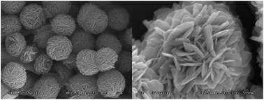
Three-dimensional (3D) flower-like iron(III) oxide–indium(III) oxide (Fe2O3–In2O3) binary metal oxide nanocomposites were successfully fabricated by a simple and economical route based on an efficient ethylene glycol mediated process. Effects of the experimental parameters such as the ratio of Fe to In, type of acid absorber, solvent, and reaction temperature and time on the morphology of the nanocomposite were discussed in detail. The nanocomposites Fe2O3–In2O3 with flower-like morphology were readily obtained by annealing the precursor. The possible reaction mechanism leading to the precursor and the self-assembly process was also proposed. The results of the thermogravimetric analyses indicated that 3D flower-like Fe2O3–In2O3 binary metal oxide nanocomposites can be used as fillers to significantly enhance the thermal resistance of silicone rubber under nitrogen.
Introduction
Iron(III) oxide (Fe2O3), as an important transition metal oxide, has been extensively used as a semiconductor compound, magnetic material, catalyst, gas sensor, and heat-resistant additive in polymer systems.1–8 Moreover, Fe2O3 is also environmentally friendly and used as a low cost adsorbent for environmental applications including decontamination of toxic metal ions, fluoride ions, and organic dyes from aqueous solutions. Compared to Fe2O3, indium(III) oxide (In2O3) is an n-type semiconductor, which exhibits good electrical conductivity and high optical transparency in the visible light region, and acts as a promising candidate in various applications, such as solar cells, liquid crystal displays, and gas sensors for detection of hazardous gases.9–14 Transition metal oxides have promising gas sensing performance due to their catalytic properties. Some transition metal oxides are stable, have low electric resistance, and good gas sensing properties. However, others have high electric resistivity and require high operating temperatures. Some of the oxides are more sensitive to oxidizing gases; however, others are more to reducing gases. Therefore, it is a natural approach to combine metal oxides with different properties in an appropriate proportion in order to modify the gas sensor performance as desired. In recent years, significant attention has been paid to the fabrication of micro- and nano-structures of Fe2O3–In2O3 binary metal oxide due to their fascinating electrical conductivity, and their potential applications, mainly in optoelectronics, catalysis, and gas sensing.9–12
Nanotechnology has attracted tremendous attention attributed to the unusual properties of the nanostructured materials known for their stability, green chemistry, and diverse technical applications. In particular, 3D nanostructures exhibit fascinating and extraordinary properties superior to their bulk and particle counterpart. Moreover, 3D binary metal oxides are obtaining progressive attention nowadays because they not only provide the synergistic effect of both the metal oxides, but also offer the advantage over the individual material in tuning the optical band gap and controlling the inter-particle electron transfer. In general, the mixed Fe2O3–In2O3 materials are prepared by conventional methods, including sol–gel procedure, hydrothermal method under critical conditions, co-precipitation method, microwave radiation method, solution combustion method, and high energy ball milling method;15–22 however, these methods result in the formation of large crystal agglomerates or low dimensional (0D, 1D, or 2D) nanoparticles. Moreover, abovementioned methods require some specials instruments in order to meet the critical conditions, thus resulting in complicated procedures.
Nowadays, an efficient polyol process, through rapid and simple economic route, has been used to fabricate a series of 3D micro/nano metal oxide materials, such as Fe2O3, Ce2O3, Co3O4, and ZnO.23–26 3D micro/nano structured metal oxide is composed of nano-sized hierarchically organized building blocks, the particle size is in the micrometer scale. Furthermore, with advancements in nanoscience and nanotechnology, multicomposite hybrid nanostructures have attracted significant attention because of their multicomponent structures which not only provide novel functions unavailable in single-composite materials or structures, but also achieve enhanced properties which break the natural constraints of single-phase materials.27 However, till date, most of the Fe2O3–In2O3 materials obtained by conventional methods have exhibited large crystal agglomerates or low dimensional nanoparticles, and the synthesis of 3D micro/nano Fe2O3–In2O3 materials, in particular, by polyol process has rarely been investigated.
In this study, 3D flower-like Fe2O3–In2O3 binary metal oxide nanocomposites were successfully fabricated by a simple and economical route based on efficient ethylene glycol mediated process. Furthermore, effects of the reaction temperature and time, solvent, different molar ratios of Fe/In, templates, and type of acid absorber on the formation of Fe2O3–In2O3 binary metal oxide phase and its shape and size were also investigated. The possible reaction mechanism leading to the precursor and self-assembly process was also proposed. Moreover, although several studies have investigated the antioxidant functions of single metal oxide as filler in silicone rubber, this study provides a new perspective to the understanding of the 3D flower-like Fe2O3–In2O3 binary metal oxide nanocomposites which can be used as fillers to significantly enhance the thermal resistance of silicone rubber under nitrogen.28–32
Results and discussion
A possible formation mechanism of the flower-like Fe and In alkoxides as the precursor was obtained based on the detailed time-dependent evolutions of morphology examined by scanning electron microscopy (SEM) at different time intervals starting from the precipitate that appeared in the reaction solution. Fig. 1a exhibits that at the early stage; the samples consist of nanoparticles with diameter of ∼50 nm. Fig. 1b shows the SEM image of the sample collected 30 min later, exhibiting the coexistence of nanoparticles and sheet-like micro/nanostructure, the length is ∼1 μm and width is ∼150 nm. With the progress in the reaction, the sheet-like structure changes from being single-layered to double-layered, and overlaps between the layers, and the size is ∼400 nm, as shown in Fig. 1c. Fig. 1d shows the coexistence of sheet-like and flower-like micro/nanostructures, with the size of ∼1 μm, respectively. Fig. 1e shows that at the reaction time of 3 h, the ratio of the flower-like micro/nanoparticles increases at the expense of the sheet-like micro/nanoparticles, and the size of flower-like particles is also ∼1 μm. Fig. 1f exhibits that at the completion of the reaction, the samples consist of only 3D flower-like micro/nanostructures with diameter of ∼1 μm, and the nanoparticles and sheet-like micro/nanoparticles are not observed. This result was consistent with the previous reports on a so-called two-stage growth process, involving a rapid nucleation of amorphous primary particles followed by a slow aggregation and crystallization of primary particles.33–35
 |
| Fig. 1 SEM images of the as-obtained Fe and In precursors with Fe/In molar ratio of 4 : 1 collected at different intervals since the precipitate occurred: (a) 5 min, (b) 30 min, (c) 1 h, (d) 2 h, (e) 3 h, and (f) 4 h. | |
Influence of the reaction temperature and calcination temperature on the morphology and size of the nanocomposite
It was observed that the reaction temperature had significant effect on the morphology and size of the as-prepared precursor. When the reaction was performed at 200 °C, the precursor exhibited the coexistence of nanoparticles and sheet-like micro/nanostructure. Even though the reaction time was increased to 12 h, the 3D flower-like structure could not be formed, similar to that at 150 °C. However, the average diameter of nanosheets was 2.5 μm at 200 °C, which was larger than that obtained at 150 °C. Moreover, compared to the single-layered nanosheets at 150 °C, the nanosheets at 200 °C were multi-layered with thickness of about 500 nm. Both of them were similar to those intermediate procedures when the reaction at 240 °C. The transformation process for Fe2O3/In2O3 precursors occurred at higher temperature and took more time than for pure Fe2O3 precursor previously reported by Wan et al.36 This is mainly attributed to the fact that low temperature (lower than 240 °C) does not possess sufficient energy to complete the Ostwald ripening process. Thus, steps 2 and 3 shown in Scheme 1 are suppressed. Therefore, the reaction temperature significantly influenced the morphology of the obtained structures. Notably, the average diameter of Fe2O3/In2O3 micro/nanostructure was 1 μm, which was lower than that of pure Fe2O3 precursor (2 μm) previously reported by Chen et al.40 This indicated that addition of In into Fe2O3 system could limit the crystal growth.
 |
| Scheme 1 Schematic illustration of the proposed mechanism of formation of 3D flower-like nanostructures. | |
Thermal decomposition of the metal alkoxides is a simple route toward the synthesis of metal oxides. In this study, sample was calcined at 300, 450, 600, and 800 °C for 3 h in air at a ramping rate of 2 °C min−1, respectively. Fig. 2 shows that the SEM images of the calcined product mainly consist of ample flower-like architecture, except at the calcination temperature of 800 °C. With the increase in the calcination temperature, the surface morphology of the product becomes relatively rough, indicating insignificant effect of the calcination temperature on the morphology of the flower-like architectures. Fig. 2e exhibits that at the calcination temperature of 800 °C, the morphology of the sample is irregular, thus exorbitant thermal treatment could destroy the flower-like architectures.
 |
| Fig. 2 Effect of different calcination temperature on the morphology of the product: (a) the as-prepared precursors, (b) 300 °C, (c) 450 °C, (d) 600 °C, and (e) 800 °C. | |
The distribution of Fe, In, and O on the surface of xFe2O3·(1 − x)In2O3 for x = 0.8 was characterized by the SEM integrated with X-ray diffraction (XRD) analysis (SEM-EDX) as shown in Fig. 3. The diagram of the sample is the image of the entire chemical element, and the spots for which the grayscales are different from the backgrounds in the other diagrams represent that the distribution of Fe, In, and O is homogeneous. The result of inductively coupled plasma-atomic emission spectroscopy (ICP-AES) was 3.99, which was almost similar to the original proportion.
 |
| Fig. 3 SEM-EDX maps of the distributions of Fe, In, and O on the surface of the Fe and In oxides. | |
Influence of tetrabutylammonium bromide (TBAB) and solvents on the morphology and size of the nanocomposite
The results indicated that TBAB played a crucial role in the synthesis of Fe2O3/In2O3 precursors in contrast to the preparation of pure Fe2O3 precursor where the absence and presence of TBAB resulted in the same morphology. However, in multicomposite hybrid nanostructures, as shown in Fig. 4a, in the absence of TBAB, mainly nanoparticles are observed and flower-like structure is not obtained. This result indicates that initial nanoparticles tend to assemble into flower-like architecture only in the presence of TBAB. This could be attributed to the fact that solution of TBAB acts as a soft template to form micelles which can direct the growth of the nanostructures and control the size of the nanosheets that constitute the flower-like structures33 (Scheme 1 step 2). According to the literature,34,35 soft-template method, using surfactants and supramolecular aggregates, such as micelles and emulsions as templates, has been proven to be an efficient technique to direct the morphology control. Moreover, TBAB molecules also facilitate the assembly of initial nanoparticles into 3D flower-like binary metal oxide nanocomposite structure through the interaction between TBAB molecules and nanoparticles, similar to that reported in the literature.36
 |
| Fig. 4 Effect of TBAB and urea on the morphology of the nanocomposite: (a) in the absence of TBAB, (b) in the presence of sodium carbonate instead of urea, and (c) in the presence of sodium acetate instead of urea. | |
Urea present in the reaction system acted as an acid absorber. Urea plays an efficient role by providing a steady supply of OH− ions which are capable of neutralizing the central metal ion releasing H+ ions, thus allowing the reaction to continue (Scheme 1 step 1). Hydroxyl groups (–OH) formed by the hydrolysis of urea neutralized the HCl and allowed the coordination reaction to be completed.21 Herein; we utilized sodium acetate and sodium carbonate to replace urea. They offered the same acid absorber action; however, with different alkalescency. Fig. 4b and c clearly show that the morphology of the as-obtained samples is not flower-like, which was similar to those intermediate procedures when the reaction with urea added as the acid absorber. It indicated that alkalescency of the acid absorber was very critical in this system.
Moreover, solvent is an important parameter for synthesis. In this study, it was found that ethylene glycol was important for the formation of hierarchically organized flower-like Fe2O3/In2O3 micro/nanostructure. When glycerol was substituted for ethylene glycol, flower-like morphology was not obtained. No obvious flower-like product was observed when ethylene glycol was replaced with 1,2-propylene glycol. This is attributed to the reductive ability of polyols which determines the formation and growth rate of nanostructures.
Influence of different molar ratios of Fe/In on the morphology and size of the nanocomposite
Seven samples were prepared under the same reaction conditions except with different molar ratios of Fe/In. When the molar ratio of Fe/In was equal to or greater than 4, the flower-like structure is obtained as shown in Fig. 5a and b. Fig. 5c shows the coexistence of sheet-like and flower-like micro/nanostructures when the molar concentration of both the metal elements is same (i.e., molar ratio is 1). Sequentially, as the molar ratio reduces to 1/4, the morphology of the obtained sample consists of sheet-like structures and nanoparticles (Fig. 5d). Finally, only nanoparticles are observed for the molar ratio of Fe/In below 1/10 (Fig. 5e). Notably, with increasing molar ratio of Fe/In, the variation in morphology of the as-prepared samples was similar to the formation mechanism of the flower-like Fe and In alkoxides as the precursor (Scheme 1).
 |
| Fig. 5 Effect of different molar ratios of Fe/In on the morphology and size of the product: (a) 10 : 1, (b) 4 : 1, (c) 1 : 1, (d) 1 : 4, and (e) 1 : 10. | |
The XRD patterns of a series of prepared samples calcined in the air at 450 °C for 3 h were analyzed to study the phase structure in relation with different molar ratios of Fe/In in this system. Fig. 6a shows the selected XRD spectra corresponding to all concentration range. For xFe2O3·(1 − x)In2O3 (x = 0.95), In2O3 phase is not detected, indicating the complete substitution of In3+ ions by Fe3+ ions in the hematite lattice. With a decrease in the concentration of Fe3+ ions, for x = 0.9 and x = 0.8, (222) faces of In2O3 appear and the diffraction intensity of (104) faces of Fe2O3 decreases. In contrast, from x = 0.5 to x = 0.05, (104) faces of Fe2O3 disappear; however, (211) faces of In2O3 are observed. Moreover, the diffraction intensity of (104) faces of In2O3 increased. Fig. 6b shows the amplified (104) and (222) diffraction peaks of the samples revealing that (222) diffraction peaks successively shift to lower degrees with the increase in the In content in the samples. This shift could be attributed to an increase in the size of the crystallographic unit cell due to the incorporation of more In possessing larger atomic size than Fe. Moreover, the diffraction lines of Fe2O3 in all the Fe–O–In system samples are shifted toward higher values with respect to those of pure Fe2O3, indicating an increase in the cell volume of Fe2O3. However, the shift of the reflection toward greater angle values is the evidence of substitution of In ions by smaller Fe ions in the In2O3 crystal lattice. The concentration regions for Fe2O3/In2O3 micro/nanostructure together with the solubility limits of In3+ ions in the hematite lattice and of Fe3+ ions in the cubic In2O3 structure have been evidenced.42
 |
| Fig. 6 (a) The XRD patterns of samples with various Fe/In ratios: H1 0.95, H2 0.9, H3 0.8, H4 0.5, H5 0.2, H6 0.1, H7 0.05; (b) the amplified diffraction peaks of the samples. | |
Nitrogen adsorption isotherms indicated that the Brunauer–Emmett–Teller (BET) specific surface area of the as-prepared xFe2O3·(1 − x)In2O3 for x = 0.8 was 29 m2 g−1. Fig. 7a and b show the complete N2 adsorption–adsorption isotherms and pore size distribution of the obtained sample. Fig. 7a shows that the isotherm can be categorized as type H3, which is characteristic of slit-type pores associated with the inter-particle porosity generated in solids having plate- or fiber-like morphology. The pore size distribution curve of the sample exhibits a broad peak around 8–40 nm.
 |
| Fig. 7 (a) N2 adsorption–adsorption isotherms and (b) pore size distribution of xFe2O3·(1 − x)In2O3 for x = 0.8. | |
3D flower-like Fe2O3–In2O3 binary metal oxide nanocomposites as fillers to enhance the thermal resistance of silicone rubber under nitrogen
Fig. 8 exhibits the TGA thermogram, revealing that the temperature at which 5% weight loss (Td5) occurs is around 415 °C for silicone rubber without metal oxide or with well dispersed common Fe2O3 as filler. However, Td5 is around 505 °C for silicone rubber with Fe2O3–In2O3 nanocomposites as fillers when the TGA analysis was performed under N2. Apparently, the common Fe2O3 filler could not improve the thermal resistance of silicone rubber; however, the thermal resistance of silicone rubber was significantly enhanced nearly by 90 °C by 3D flower-like Fe2O3–In2O3 nanocomposites. This indicated that the 3D flower-like Fe2O3–In2O3 binary metal oxide nanocomposites could efficiently inhibit the back-biting reactions at high temperature.37–42 Therefore, this study provides a new perspective to the understanding of an important method to enhance the thermal resistance of silicone rubber. Thus, the thermal resistance can be increased by controlling the morphology and structure of nanocomposites or by using different types of metal oxides. However, the mechanism has not been investigated sufficiently and it has not been clearly understood. Undeniably, a lot more systematic explorations are demanded in order to better understand the mechanism of this phenomenon which will be pursued in our successive studies.
 |
| Fig. 8 The TGA trace of silicone rubber without and with different fillers, the Fe2O3–In2O3 nanocomposites is xFe2O3·(1 − x)In2O3 for x = 0.8. | |
Conclusions
3D flower-like Fe2O3–In2O3 binary metal oxide nanocomposites were successfully fabricated by an efficient polyol process. The results indicated that it was possible to control the morphology and structure of Fe2O3–In2O3 composites by adjusting the experimental parameters such as reaction temperature and time, solvent, different molar ratios of Fe/In, templates, and acid absorber. This synthetic route allowed us to obtain the 3D flower-like composite structure and solid solutions in an extended concentration range. Furthermore, the 3D flower-like Fe2O3–In2O3 binary metal oxide nanocomposites could be efficiently used as filler to significantly enhance the thermal resistance of silicone rubber under nitrogen.
Experimental
Materials and synthesis
All the chemicals were of analytical grade and used as received without further purification. In a typical procedure involving the fabrication of Fe2O3–In2O3 binary metal oxide nanocomposite, ferric chloride (FeCl3·6H2O, 0.96 g, 3.80 mmol), indium nitrate (In(NO3)3·5H2O, 0.37 g, 0.95 mmol), urea (2.7 g), and tetrabutylammonium bromide (TBAB, 7.2 g) were dissolved in ethylene glycol (180 mL). The solution was refluxed at 220 °C for 4 h. Subsequently, the contents were cooled down and the as-synthesized Fe and In oxides precursors were collected by four centrifugation and ethanol washing cycles. The obtained samples were dried in an oven at 70 °C for 10 h, followed by calcination at 450 °C for 3 h in air at a ramping rate of 2 °C min−1. The yield of the obtained product was ca. ∼0.39 g (89.7%). (InxFe1−x)2O3 crystals with different molar ratio of Fe/In were prepared according to the typical procedure described above. The total concentration of metal ions was kept at 0.007 mol L−1; however, the initial concentrations of In and Fe in solution were varied. The silicone rubber was vulcanized by tetraethoxysilane with 25% SiO2 and 5% metal oxide as fillers.
Characterizations
The structure of the nanocomposites was characterized by the powder X-ray diffraction (XRD) measurements performed on a Shimadzu XRD-6000 X-ray diffractometer (Cu Kα radiation, λ = 15
406 Å). Morphologies of the samples were investigated using a Cambridge S-4300 scanning electron microscope (SEM). The specimens were coated with gold prior to their observation at the accelerating voltage of 15 kV. A Cambridge S-6700 SEM at the accelerating voltage of 5 kV was also employed in this study. The nitrogen adsorption–desorption isotherms at 77 K were measured using a micromeritics ASAP 2020 V3.00 H system. Inductively coupled plasma-atomic emission spectroscopy (ICP-AES) was performed on Plasma1000 to determine the composition of the nanocomposite before the samples were completely solved and the ion concentrations were kept at 50 ppm. Thermogravimetric analyses (TGA) were performed on a SII EXTRA 6300 TG/DTA apparatus, using 6–10 mg of polymer, at a heating rate of 10 K min−1 with nitrogen as the purge gas at 20.0 mL min−1.
Acknowledgements
The authors acknowledge the financial support from the National Natural Science Foundation of China (no. 50803070).
Notes and references
- Q. Guo, S. Kim, M. Kar, W. Shafarman, R. Birkmire, E. Stach, R. Agrawal and H. Hillhouse, Nano Lett., 2008, 8, 2982–2987 CrossRef CAS PubMed.
- S. Karthikeyan, C. Judia Magthalin, A. B. Mandala and G. Sekaran, RSC Adv., 2014, 4, 19183–19195 RSC.
- M. Hu, J.-S. Jiang, F.-X. Bu, X.-L. Cheng, C.-C. Lin and Y. Zeng, RSC Adv., 2012, 2, 4782–4786 RSC.
- G. X. Do, B. J. Paul, V. Mathew and J. Kim, J. Mater. Chem. A, 2013, 1, 7185–7190 CAS.
- Y. Kido, K. Nakanishi and K. Kanamori, RSC Adv., 2013, 3, 3661–3666 RSC.
- N. Basavegowda, K. Mishra and Y. R. Lee, RSC Adv., 2014, 4, 61660–61666 RSC.
- L. Gu, R. H. Fang, M. J. Sailor and J.-H. Park, ACS Nano, 2012, 6, 4947–4954 CrossRef CAS PubMed.
- Y. Kido, K. Nakanishi, A. Miyasaka and K. Kanamori, Chem. Mater., 2012, 24, 2071–2077 CrossRef CAS.
- B. Koo, S. Chattopadhyay, T. Shibata, V. B. Prakapenka, C. S. Johnson, T. Rajh and E. V. Shevchenko, Chem. Mater., 2013, 25, 245–252 CrossRef CAS.
- L. Wortmann, S. Ilyas, D. Niznansky, M. Valldor, K. Arroub, N. Berger, K. Rahme, J. Holmes and S. Mathur, ACS Appl. Mater. Interfaces, 2014, 6, 16631–16642 CAS.
- E. Boros, A. M. Bowen, L. Josephson, N. Vasdev and J. P. Holland, Chem. Sci., 2015, 6, 225–236 RSC.
- Y. Jung, S. Lee, D. Ko and R. Agarwal, J. Am. Chem. Soc., 2006, 128, 14026–14027 CrossRef CAS PubMed.
- J. Luther, M. Law, M. Beard, Q. Song, M. Reese, R. Ellingson and A. Nozik, Nano Lett., 2008, 8, 3488–3492 CrossRef CAS PubMed.
- M. G. Panthani, V. Akhavan, B. Goodfellow, J. P. Schmidtke, L. Dunn, A. Dodabalapur, P. F. Barbara and B. A. Korgel, J. Am. Chem. Soc., 2008, 130, 16770–16777 CrossRef CAS PubMed.
- H. Peng, C. Xie, D. Schoen and Y. Cui, Nano Lett., 2008, 8, 1511–1516 CrossRef CAS PubMed.
- H. Tu and D. Kelley, Nano Lett., 2006, 6, 116–122 CrossRef CAS PubMed.
- K. Park, K. Jang, S. Kim, H. Kim and S. Son, J. Am. Chem. Soc., 2006, 128, 14780–14781 CrossRef CAS PubMed.
- D. T. Schoen, H. L. Peng and Y. Cui, J. Am. Chem. Soc., 2009, 131, 7973–7975 CrossRef CAS PubMed.
- Y. Yang and Y. Chen, J. Phys. Chem. B, 2006, 110, 17370–17374 CrossRef CAS PubMed.
- M. Ng, C. Boothroyd and J. Vittal, J. Am. Chem. Soc., 2006, 128, 7118–7119 CrossRef CAS PubMed.
- X. Sun, B. Yu, G. Ng, T. Nguyen and M. Meyyappan, Appl. Phys. Lett., 2006, 89, 233121 CrossRef PubMed.
- B. Yu, S. Ju, X. Sun, G. Ng, T. Nguyen, M. Meyyappan and D. Janes, Appl. Phys. Lett., 2007, 91, 133119 CrossRef PubMed.
- M. Ettenberg, Adv. Imaging, 2005, 20, 29–32 Search PubMed.
- E. Fossum, IEEE Micro, 1998, 18, 8–15 CrossRef.
- S. Kim, Y. T. Lim, E. G. Soltesz, A. M. DeGrand, J. Lee, A. Nakayama, J. A. Parker, T. Mihaljevic, R. G. Laurence, D. M. Dor, L. H. Cohn, M. G. Bawendi and J. V. Frangioni, Nat. Biotechnol., 2004, 22, 93–97 CrossRef CAS PubMed.
- J. Tang, G. Konstantatos, S. Hinds, S. Myrskog, A. Pattantyus-Abraham, J. Clifford and E. Sargent, ACS Nano, 2008, 3, 331–338 CrossRef PubMed.
- J. Wang, M. Gudiksen, X. Duan, Y. Cui and C. Lieber, Science, 2001, 293, 1455–1457 CrossRef CAS PubMed.
- T. Suzuki, Polymer, 1989, 30, 333–337 CrossRef CAS.
- M. Cypryk, B. Delczyk, A. Juhari and K. Koynov, J. Polym. Sci., Part A: Polym. Chem., 2009, 47, 1204–1216 CrossRef CAS PubMed.
- T. H. Thomas and T. C. Kendrick, J. Polym. Sci., Part A-2, 1970, 8, 1823–1830 CrossRef CAS PubMed.
- T. H. Thomas and T. C. Kendrick, J. Polym. Sci., Part A-2, 1969, 7, 537–549 CrossRef CAS PubMed.
- P. B. Kevin, C.-M. Kuo, L. M. Robert and C. S. John, Macromolecules, 1995, 28, 790–792 CrossRef.
- J. Zhao, Y. Guo, H. Guo, Y. Chai, Y. Li, Y. Liu and C. Liu, Inorg. Chem. Commun., 2012, 18, 21–24 CrossRef CAS PubMed.
- C. Cheng, F. Xu and H. Gu, New J. Chem., 2011, 35, 1072–1079 RSC.
- M.-K. Jia, G.-J. Su, M.-H. Zhang, B. Zhang and S.-J. Lin, Sci. China: Chem., 2010, 53, 1266–1272 CrossRef CAS PubMed.
- L.-S. Zhong, J.-S. Hu, H.-P. Liang, A.-M. Cao, W.-G. Song and L.-J. Wan, Adv. Mater., 2006, 18, 2426–2431 CrossRef CAS PubMed.
- H.-F. Fei, W. Xie, Q. Wang, X. Gao, T. Hu, Z. Zhang and Z. Xie, RSC Adv., 2014, 4, 56279–56287 RSC.
- M. Nishizawa, K. Mukai, S. Kuwabata, C. R. Martin and H. J. Yoneyama, Electrochem. Soc., 1997, 144, 1923–1926 CrossRef CAS PubMed.
- Y. Wang, K. Takahashi, H. Shang and G. Cao, J. Phys. Chem. B, 2005, 109, 3085–3088 CrossRef CAS PubMed.
- J. Chen, L. N. Xu, W. Y. Li and X. L. Gou, Adv. Mater., 2005, 17, 582–586 CrossRef CAS PubMed.
- H. Morimoto, S. I. Tobishima and Y. J. Iizuka, Power Sources, 2005, 146, 315–318 CrossRef CAS PubMed.
- Q. R. Zhao, Y. Gao, X. Bai, C. Z. Wu and Y. Xie, Eur. J. Inorg. Chem., 2006, 8, 1643–1648 CrossRef PubMed.
|
This journal is © The Royal Society of Chemistry 2015 |
Click here to see how this site uses Cookies. View our privacy policy here.