DOI:
10.1039/C5RA05625J
(Paper)
RSC Adv., 2015,
5, 35909-35916
Polyvinylidene fluoride based lightweight and corrosion resistant electromagnetic shielding materials
Received
30th March 2015
, Accepted 10th April 2015
First published on 10th April 2015
Abstract
Various NixCo1−x alloys (with x varying from 0–60 wt%, Ni: nickel, Co: cobalt) were prepared by vacuum arc melting and mixed with polyvinylidene fluoride (PVDF) to design lightweight, flexible and corrosion resistant materials that can attenuate electromagnetic radiation. The saturation magnetization scaled with the fraction of Co in the alloy. Two key properties such as high-magnetic permeability and high-electrical conductivity were targeted. While the former was achieved using a Ni–Co alloy, multiwalled carbon nanotubes (CNTs) in the composites accomplished the latter. A unique approach was adopted to prepare the composites wherein PVDF powder along with CNTs and Ni–Co flakes were made into a paste, using a solvent, followed by hot pressing. Interestingly, CNTs facilitated in uniform dispersion of the Ni–Co alloy in PVDF, as manifested from synergistic improvement in the electrical conductivity. A significant improvement in the shielding effectiveness (41 dB, >99.99% attenuation) was achieved with the addition of 50 wt% of Ni40Co60 alloy and 3 wt% CNTs. Intriguingly, due to the unique processing technique adopted here, the flexibility of the composites was retained and more interestingly, the composites were resistant to corrosion as compared to only Ni–Co alloy.
1 Introduction
Electromagnetic (EM) interference has become a major concern because of increasing demand for electronic equipment and various devices operating at high frequencies.1–5 Devices like wireless computers, mobile phones, microwaves and radios emit EM radiation.3,4,6 This EM radiation can cause severe damage to the system itself and/or other electronic devices in the vicinity ultimately leading to malfunctioning of devices.1 Further, advancement in nanotechnology has resulted in densely packed2 electronic components within an instrument causing electronic noise and creating a problem of interference with other systems by radiation. These emissions, in addition, have adverse effects on the human body and causes serious damage to human tissues.1,2,6 EM frequencies ranging from low to high causes flow of current through human body and generate heat and thermal injury to the human system.1,2,6 High frequency sources such as mobile phones, WLAN1etc. affects the nervous system.2 Therefore, devices that are vulnerable to EM radiation need to be shielded to avoid their malfunctioning. It is, therefore, important to understand the properties and behavior of EM radiations in order to shield them.
EM radiations are due to synchronized oscillations of electric and magnetic fields at right angles to each other and to the direction of propagation.5,7,8 These radiations can be arrested or reduced by either absorption and/or reflection. Conducting polymer matrix composites have received significant attention in effective shielding of EM radiations due to their high conductivity and dielectric constant.5,9 The absorption loss in the shielding material is a function of magnetic permeability and the conductivity of the material.5 Therefore, incorporating magnetic particles within conducting polymer composites can promise materials that can attenuate the radiations. Therefore, these materials will possess a unique combination of both magnetic and electrical dipoles in the system. Conducting fillers such as carbon black, metallic particles, carbon nanotubes (CNTs), graphene etc. are the most widely used materials for improving the conductivity of a polymer matrix.5,7,8,10 The ability of metals to conduct heat and electricity is the reason for their widespread use in EMI shielding. However, the disadvantages with metals are their bulkiness, poor processability, and poor oxidation resistance. In addition, metallic coating is costly since it consists of at least two processing steps, such as one for the support and other for the coating. Moreover, it is very difficult to coat intricate shapes.7 In this context, low-density carbon nanostructures are effective material for EM interference shielding as it has high current density. In addition, they have high aspect ratio, which facilitates interconnected network like structure at relatively lower fractions. Overall, these properties makes CNT based polymeric composites a promising candidate8,11 over conventional materials.
In the recent past, ferromagnetic particles like Fe Co, Ni and their alloy have received a great deal of attention due to their potential use as electromagnetic shielding materials in the gigahertz frequency region. In addition, owing to their high Snoek's limit12 they are ideal candidates among the metallic and alloy magnet class of materials.13 Further, carbon/ferromagnetic composites exhibit a good balance between permittivity and permeability.14–18
In the light of the existing literature, we aim to develop lightweight, flexible, and corrosion resistant polymeric composites containing small volume fractions of ferromagnetic material with high magnetic permeability and intrinsically conducting nanomaterials like CNTs. Therefore, nickel–cobalt alloys with different compositions were prepared by vacuum arc melting process and mixed with CNTs using a unique processing technique for shielding EM radiations. Polyvinylidene fluoride (PVDF) was chosen as a matrix because of its high dielectric constant, good mechanical properties, thermal stability and chemical resistance.11 Arranz-Andrés et al. reported that a shielding effectiveness (SE) of 110 dB on addition of 25 vol% of copper in the PVDF matrix.3 Chung et al. achieved shielding effectiveness of 90 dB in the range of 1–2 GHz by coating carbon filaments with nickel (94 vol%) in polyether sulfone.19,20 Gong et al. reported ca. 25 dB with 50 wt% Ni in resin based matrix.21 Recently, we have reported SE of 30 dB with 3 wt% CNTs in PVDF matrix. The results obtained in our previous work further motivated us to systematically study the effect of Ni–Co alloy on the shielding effectiveness in PVDF based composites. Flakes of Ni–Co alloy was chosen over fine powder as they possess high permeability than the spherical particle12 especially, in the GHz range.14,22–24 The properties of CNTs and Ni–Co alloy will provide synergistic improvement in the key properties like electrical conductivity, magnetic permeability and dielectric properties that are required to design an efficient shield against EM radiation. The structure, morphology and the EMI shielding properties of the composites has been discuss in detail and summarized.
2 Experimental
2.1 Materials and methods
Nix Co1−x alloys (x = 0–60 wt%) were prepared by vacuum arc melting technique from high purity elemental constituents. The as-cast alloys were subjected to hot rolling followed by homogenization anneal and then air-cooled. The microstructural details of Ni–Co alloys have been already reported in our previous study.25,26 Ni–Co alloy powder (flaky shaped) was obtained by filing with a diamond file. Commercially available PVDF (Kynar 741), supplied by Arkema, was used in this work. The pristine CNTs were obtain from Nanocyl (NC 7000). Both PVDF and the flakes were mixed using a mortar pestle for 30 min and the solvent (dimethylformamide, DMF) was added drop-wise to make a paste. This unique approach was adopt because the metal powder tends to agglomerate during processing either in solution or in melt. The resultant paste was then vacuum dried to remove the traces of solvent followed by compression moulding at 220 °C in a laboratory scale hot press. PVDF with 50 wt% Ni40Co60 alloy and PVDF + 3 wt% CNTs + 50 wt% Ni40Co60 alloy was prepared employing the above mentioned procedure.
2.2 Characterization
The magnetic response of various Ni–Co flakes and the composites were obtain using vibrating sample magnetometer (VSM). The morphology and the state of dispersion of the flakes and CNTs in PVDF were investigated by employing a field emission scanning electron microscope (FEI Sirion XL30 FEG SEM). The composite samples were cryo-fractured prior to SEM. The X-ray diffraction patterns were studied using a PANalytical X'pert Pro (Cu Kα, λ = 0.154 nm). Toroidal samples were prepared for evaluating the scattering parameters in the frequency range of 2–18 GHz using Anritsu MS4642A Vector Network Analyzer (VNA). Electrical conductivity of hot pressed discs (10 mm) was measured by employing an Alpha-N analyser (Novocontrol) with a broad frequency range of 10−1 to 107 Hz. The corrosion resistance of the composite sample was compared with Ni–Co alloy by Potentio-dynamic polarization in 0.5% NaCl media. The test was conducted by employing a platinum strip, saturated calomel electrode and Ni–Co alloy (or composite sample) as a counter electrode, reference electrode and working electrode respectively. The corrosion current density (Icorr) and potential (Ecorr) were determined with the Tafel plot. The scan rate for polarization was 12 mV min−1 from −150 mV to +1500 mV relative to the rest potential.
3 Results and discussion
3.1 Preparation and characterization of Ni–Co alloy
Fig. 1a illustrates schematically the preparation of Ni–Co alloy using vacuum arc melting process. The microstructure of the hot rolled and homogenization annealed alloy is illustrated in Fig. 1b. The ingot, thus obtained was filed to obtain into powder of specific size. The morphology of the powder, as revealed by SEM, is flaky (Fig. 1c) with size of ca. 3–4 μm. Fig. 1d shows the XRD pattern for Ni–Co flakes. Three peaks at 44.48°, 51.66° and 76.06°, corresponding to (111), (200) and (220) plane of Ni–Co alloy are observed indicating that the as prepared Ni–Co alloy is a solid solution with face-centred cubic (FCC). The XRD pattern also indicates absence of impurity or second phase in the Ni–Co alloy. Fig. 1e shows the typical hysteresis loop for pure nickel and Ni–Co alloy (20, 40, 60 wt% Co) flakes obtained at room temperature using a magnetic field of 2 T. The saturation magnetization scales with cobalt concentration in the alloy. The values of saturation magnetization for pure Ni, Ni80Co20, Ni60Co40 and Ni40Co60 are 50.2, 74.1, 101.2 and 117.3 emu g−1, respectively. Thus, Ni40Co60 shows the highest magnetic permeability compared to pure nickel and other composition. Therefore, it is desirable to design composites using Ni40Co60 to obtain materials that can attenuate EM radiation mostly by absorption.
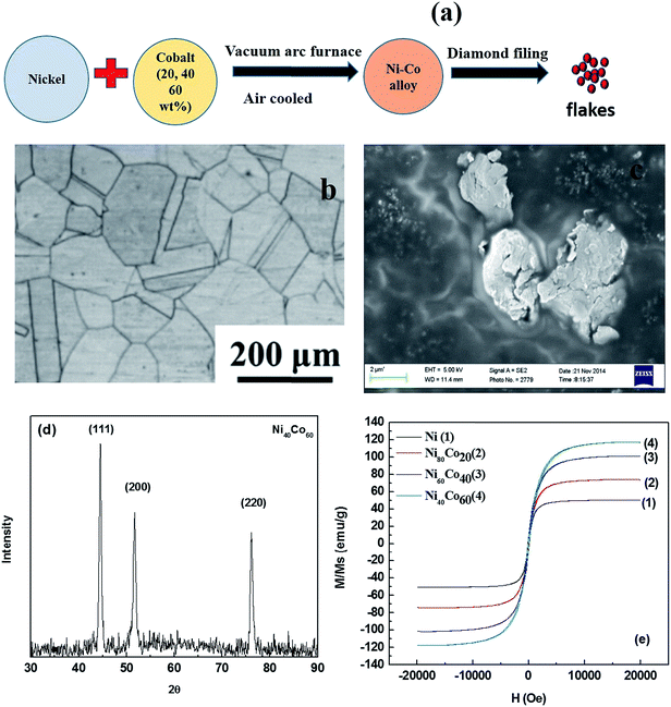 |
| | Fig. 1 (a) Processing of Ni–Co alloy (b) SEM image of Ni–Co alloy flakes (c) microstructure of the hot rolled plus homogenization annealed alloy, (d) XRD pattern for Ni–Co alloy powder (e) hysteresis loop for Ni–Co alloy with varying concentration of cobalt. | |
3.2 Preparation and characterization of PVDF based composites
Fig. 2a schematically illustrates the preparation of PVDF/CNT/Ni40Co60 composite. The slurry is prepared by physically mixing the constituents by drop-wise addition of solvent. Subsequently the composite is hot pressed after vacuum dried as shown in Fig. 2a. This unique process was adopted for two main reasons. Firstly, metal flakes usually settle during the composite preparation by solution mixing process. Secondly, they tend to re-agglomerate during melt blending. By employing this process, we believe, that the metal flakes together with CNT can be dispersed well in PVDF. The XRD patterns of as prepared PVDF/CNT/Ni40Co60 composite and PVDF/Ni40Co60 composite are shown in Fig. 2b. In addition to the three FCC peaks corresponding to Ni–Co alloy in the XRD pattern, it shows three additional peaks at 18.46°, 20.09° and 26.76° which corresponds to (020), (110) and (021) of PVDF. Fig. 2c shows the comparative hysteresis loop for PVDF/CNT/Ni40Co60 and PVDF/Ni40Co60 composites. From Fig. 2c, it is clear that the saturation magnetization decreased after the addition of PVDF. The saturation magnetization of PVDF with Ni40Co60 (20% by wt) is 19.2 emu g−1 compared to PVDF/CNTs (3% by wt)/Ni40Co60 (50% by wt) composite which showed 50.63 emu g−1. It is well evident that the magnetic permeability of PVDF/CNT/Ni40Co60 is higher than that of PVDF/NiCo60 (20%wt) respectively are 2.5 × 10⁻³ and 9.8 × 10⁻⁴ H m−1. The magnetic permeability of PVDF/CNTs-NiCo60 is almost similar to pure nickel (Fig. 1d and 2(c)).
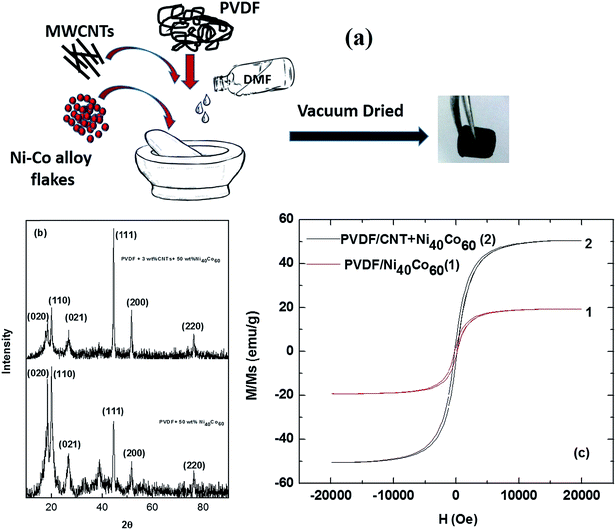 |
| | Fig. 2 (a) Preparation of PVDF/CNT/Ni–Co composite (b) XRD pattern for PVDF/CNTs-Ni-Co composite (c) hysteresis loop for PVDF/Ni40Co60 and PVDF/CNT/Ni40Co60 composite. | |
The SEM images of neat PVDF, PVDF/Ni40Co60, PVDF/CNTs and PVDF/CNT/Ni40Co60 composites are shown in Fig. 3a–d. It is observed that both CNTs and Ni–Co alloy flakes are relatively well dispersed in PVDF. Interestingly, Fig. 3d shows that the CNTs are well connected in presence of Ni40Co60 flakes. Such phenomenal dispersion can result in significant enhancement in the bulk electrical conductivity and will be discussed in the subsequent section.
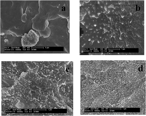 |
| | Fig. 3 SEM images of PVDF/CNT/Ni40Co60 composites: (a) neat PVDF (b) PVDF/Ni40Co60 (c) PVDF/CNTs (d) PVDF/CNT/Ni40Co60. | |
3.3 Synergistic improvement in electrical conductivity: effect of Ni–Co alloy and CNT
Fig. 4 shows the AC electrical conductivity of the composites as a function of frequency. The electrical conductivity of insulating PVDF has increased to 1.7 × 10⁻⁵ S cm−1 with the addition of 3 wt% CNTs as observed from Fig. 4. The addition of Ni40Co60 flakes (20 wt%) has shown slight increase in conductivity (6.5 × 10⁻⁵ S cm−1). Interestingly, the electrical conductivity significantly enhanced to 1.7 × 10⁻⁴ S cm−1 on addition of 3 wt% CNTs and 50 wt% Ni40Co60 flakes in PVDF. Such an impressive improvement in the electrical conductivity suggests synergistic improvement from both Ni–Co and CNTs. In order to understand the mechanism of charge transport in PVDF based composites, the AC electrical conductivity data was fitted using a power law27–29 expressed as,| | | σAC(ω) = σDC(ω) + A(ω)s | (1) |
where, σDC is the DC conductivity at ω → 0, ω is the angular frequency and A and s, are frequency and temperature dependent parameters. The value of s, determined from the fits of ln(σ) with ln(ω), indicates the conduction mechanism in the sample. The value of s is ca. 0.65 for PVDF/CNT/Ni40Co60 composites suggesting tunnelling of electrons.
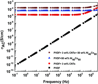 |
| | Fig. 4 Dependence of electrical conductivity on frequency for PVDF composite with different concentration of Ni40Co60 alloy and CNTs. Black solid line indicates the fitted data. | |
3.4 Attenuating electromagnetic waves: effect of Ni–Co alloy and CNT
Shielding by absorption (SEA), reflection (SER) and total shielding effectiveness (SET) are evaluated from the scattering parameters (S11 and S12) using the following equations,| | SEA = 10![[thin space (1/6-em)]](https://www.rsc.org/images/entities/char_2009.gif) log10((1 − [S11]2)/[S12]2) log10((1 − [S11]2)/[S12]2) | (2) |
| | SER = 10![[thin space (1/6-em)]](https://www.rsc.org/images/entities/char_2009.gif) log10(1/(1 − [S11]2)) log10(1/(1 − [S11]2)) | (3) |
| | SET = SEA + SER = 10![[thin space (1/6-em)]](https://www.rsc.org/images/entities/char_2009.gif) log10(1/[S12]2) log10(1/[S12]2) | (4) |
Fig. 5a shows the shielding effectiveness of PVDF/NiCo composite with different composition of NiCo alloy. It is evident that shielding effectiveness scales with increasing concentration of Co in the composites. It has already been reported that the control PVDF is transparent to EM radiation.8 The maximum SE with 60 wt% cobalt is ca. 27 dB. On the other hand, after addition of 20 and 40 wt% cobalt, the SE achieved are 17 and 23 dB respectively while only 13 dB of SE is achieved without addition of cobalt. The increase in shielding effectiveness is due to relatively higher magnetic permeability of Co as compared to Ni. From the calculated values of reflection and absorption parameters, it is evident that absorption dominates over reflection. At 3 wt% CNTs in PVDF matrix, SE value of the composite reached 22 dB while with the addition of 50 wt% of Ni40Co60 flakes, a drastic increase in the SE ca. 41 dB has been observed as shown in Fig. 5b. This sudden jump in the SE value is due to the synergistic effect of the conducting CNTs and high permeability of Ni40Co60 flakes.
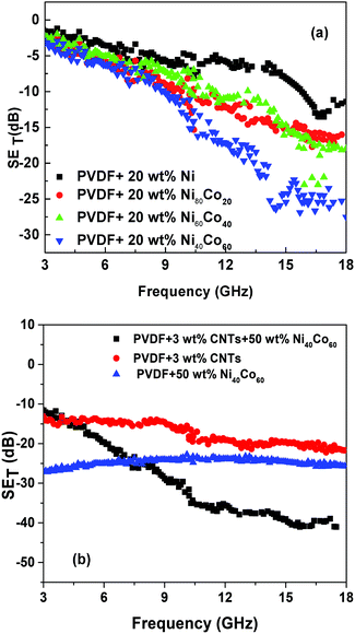 |
| | Fig. 5 Shielding effectiveness (a) PVDF composites with different concentration of Ni–Co alloy (b) PVDF composites with different concentration Ni–Co alloy and CNTs. | |
EM absorbing characteristics were evaluated by relative complex permittivity and permeability. The real and imaginary parts represent the storage and loss of EM wave energy, respectively. The relative complex permittivity and permeability were calculated from the scattering parameters (S11 and S12) obtained from the VNA in the range of 2–18 GHz by the Nicolson–Ross model.30 The sum and difference of scattering parameters can be expressed as follows:
The reflection coefficient on the interface with air-filled coaxial line can be expressed using the following equation:
| |  | (7) |
Similarly, the transmission coefficient of the specimen with particular thickness t can be expressed as below:
| |  | (8) |
where,
εR and
μR are complex permittivity and permeability respectively.
Z0 is characteristic impedance and
Z is new characteristic impedance of specimen.
Therefore, reflection coefficient may be calculated from scattering parameters as shown below.
| |  | (9) |
where,
| |  | (10) |
For |Γ| ≤ 1 appropriate sign can be chosen.
From (8) and (9) we can define,
| |  | (11) |
| |  | (12) |
Thus, the relative permeability and permittivity is expressed as,
| |  | (13) |
| |  | (14) |
The frequency dependent relative permittivity and relative permeability of PVDF/CNTs-Ni40Co60 composite are shown in Fig. 6a and b, respectively. The relative permittivity profile shows two broad peaks in the frequency range of 8–11 and 15–17 GHz, as observed from Fig. 6a. The peaks correspond to relaxation loss associated with interfacial polarization occurring due to electronegativity difference between Ni–Co alloy and CNTs.14,24 It is important to note that the peaks at 6 and 15 GHz also suggest the resonance behaviour in the system. This is possible only when the composite sample is highly conducting exhibiting skin effect.31,32
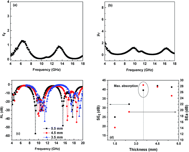 |
| | Fig. 6 (a) Relative complex permittivity and (b) permeability (c) dependence of RL on frequency at different thicknesses for PVDF + 3 wt% CNTs + 50 wt% Ni40Co60 composite (d) absorption and total SE with different thickness for PVDF + 3 wt% CNTs + 50 wt% Ni40Co60 composite. | |
Similarly, three peaks were observed in the relative complex permeability profile as shown in Fig. 6b. These peaks correspond to resonance peaks at a certain frequency and refers to high magnetic loss.33 These magnetic losses could be due to eddy current effect, hysteresis loss, flux shunting,34 natural resonance and exchange resonance.14 The dominant shielding mechanism and subsequently the SE depend on the geometry of the shield (and source), frequency of the source and the material parameters.35 A conducting shell with low permeability can also be effective shielding material due to eddy currents.34 Therefore, higher SE can be obtained either by increasing the material permeability or the material thickness.35 In the present context, eddy current loss is the dominant shielding mechanism.14,34
The EM wave consists of electric and magnetic field, which oscillates perpendicular to each other and to the direction of energy propagation. It is envisaged that when a conductor is subjected to an external electric field, within a very short time, the mobile charge inside the medium will rearrange themselves in such a way that they neutralize the effect of the original electric field. Inside an isolated conductor at equilibrium, no electrostatic field can exist. Therefore, inside a conductor, the macroscopic charge density is zero, so a net charge can exist only at the surface in a conducting material. Hence, the inner region is shielded from the effects of the external electrostatic field.
In addition, at low frequencies, the magnetic field is either due to the electric current flowing inside the conductors or due to the magnetization of surrounding ferromagnetic materials. The shield in fact causes a change in the behavior of the field, diverting the lines of the magnetic induction away from the shielded region.
Fig. 6c shows the dependence of reflection loss calculated using the following equations,
| | | Zin = Z0(μR/εR)1/2tanh[j(2πft/c)(μRεR)1/2] | (15) |
| | RL = 20![[thin space (1/6-em)]](https://www.rsc.org/images/entities/char_2009.gif) log|(Zin − Z0)/(Zin + Z0)| log|(Zin − Z0)/(Zin + Z0)| | (16) |
where,
t is the thickness of the absorber,
f is the frequency of the EM wave,
c is the velocity of the light,
Z0 is the impedance of vacuum and
Zin is the input impedance of the absorber.
14,30
The shield thickness is another key factor; if penetration is the dominant mechanism, a thicker shield results in improved shielding. An EM field can be diverted by means of an alternative path, not necessarily enclosing the area to be shielded. Such a path may offer better propagation characteristics to the electric field (by means of highly conducting materials), the electric induction (by means of high permittivity materials), the magnetic induction (high permeability materials). From Fig. 6d, it is evident that the reflection loss (RL) values depend on the thickness of the samples. As the thickness increases, the RL shifts to lower frequency.14 It is clear that PVDF/CNT/Ni40Co60 composite exhibits strong absorption in the measured range of frequency. The RL for PVDF/CNT/Ni40Co60 composite sample with 5.5 mm thickness is ca. 56.5 dB at 4.29 GHz. In addition, a minimum RL of ca. 43.1 dB at 11.4 GHz for the sample of 3.5 mm thickness and a RL of ca. 44.1 dB at 18.6 GHz for the sample of 4.5 mm thicknesses was observed. It is envisaged that high frequency can penetrate only a thin surface of electrically conducting material known as skin depth (δ), defined as the depth at which the field drops to 1/e of the incident value and is represented as follows,
| |  | (17) |
where,
f is the frequency,
σ is the electrical conductivity,
μ is the magnetic permeability and
t is the thickness of the material. A skin depth of 1.09 mm was achieved for 5.5 mm thick sample and it can be concluded that PVDF/CNT/Ni
40Co
60 composite can absorb microwave radiation. The absorption and total shielding effectiveness for PVDF/CNT/Ni
40Co
60 composite with different thickness is shown in
Fig. 6d. Maximum absorption was obtained for the sample with 3.5 mm thickness (71%).
3.5 Corrosion resistant composites
The corrosion resistance of PVDF/CNTs-Ni40Co60 composite and Ni40Co60 alloy was carried out by using Potentio-dynamic polarization in 0.5% NaCl solution. The corrosion potential (Ecorr) and corrosion current density (Icorr) were evaluate from Tafel extrapolation method. From Fig. 7, it is evident that the corrosion rate has decreased from 7.76 × 10⁻⁵ to 2.34 × 10⁻⁵ mA cm−2 after incorporation of Ni40Co60 alloy in PVDF/CNT composites. Thus, these composites can be further be explored as lightweight, corrosion resistant materials for attenuating EM radiation.
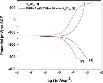 |
| | Fig. 7 Potentio-dynamic polarization plots in 0.5% NaCl solution. | |
4 Conclusions
Lightweight, flexible, and corrosion resistant PVDF based composites was prepared using a unique process. The Ni–Co alloy was prepared by vacuum arc melting process and mixed with CNTs. The XRD pattern for Ni–Co alloy shows FCC crystal structure. The VSM study confirms that the PVDF/CNT/Ni40Co60 composite show almost similar saturation magnetization as that of neat Nickel. In addition, 50 wt% of Ni40Co60 in PVDF/CNT composites showed significant improvement in electrical conductivity as compared to PVDF/CNTs and PVDF/Ni40Co60 composites. Intriguingly, PVDF/CNT/Ni40Co60 composite showed an impressive enhancement in SE and absorbed ca. 70% of the total incident EM radiation.
Acknowledgements
The authors like to acknowledge Department of Science and Technology DST, India for financial support. Authors also like to acknowledge Prof. Subodh Kumar for extending corrosion facilities.
References
- A. Ahlbom, J. Bridges, R. De Seze, L. Hillert, J. Juutilainen, M.-O. Mattsson, G. Neubauer, J. Schüz, M. Simko and K. Bromen, Toxicology, 2008, 246, 248–250 CrossRef PubMed.
- K. Jagatheesan, A. Ramasamy, A. Das and A. Basu, Indian J. Fibre Text. Res., 2014, 39, 329–342 CAS.
- J. Arranz-Andrés, E. Pérez and M. Cerrada, Eur. Polym. J., 2012, 48, 1160–1168 CrossRef.
- J. Arranz-Andrés, N. Pulido-González, C. Fonseca, E. Perez and M. Cerrada, Mater. Chem. Phys., 2013, 142, 469–478 CrossRef.
- V. Udmale, D. Mishr, R. Gadhave, D. Pinjare and R. Yamgar, Orient. J. Chem., 2013, 29, 927–936 CrossRef CAS.
- S. Aalto, C. Haarala, A. Brück, H. Sipilä, H. Hämäläinen and J. O. Rinne, J. Cereb. Blood Flow Metab., 2006, 26, 885–890 CrossRef PubMed.
- S. P. Pawar, K. Pattabhi and S. Bose, Assessing the critical concentration of NH2 terminal groups on the surface of MWNTs towards chain scission of PC in PC/SAN blends: effect on dispersion, electrical conductivity and EMI shielding, RSC Adv., 2014, 4(36), 18842–18852 RSC.
- M. Sharma, M. P. Singh, C. Srivastava, G. Madras and S. Bose, ACS Appl. Mater. Interfaces, 2014, 6, 21151–21160 CAS.
- M. Oyharçabal, T. Olinga, M.-P. Foulc, S. Lacomme, E. Gontier and V. Vigneras, Compos. Sci. Technol., 2013, 74, 107–112 CrossRef.
- A. P. Singh, B. K. Gupta, M. Mishra, G. A. Chandra, R. B. Mathur and S. K. Dhawan, Carbon, 2013, 56, 86–96 CrossRef CAS.
- M. Sharma, S. Sharma, J. Abraham, S. Thomas, G. Madras and S. Bose, Mater. Res. Express, 2014, 1, 035003 CrossRef.
- J. Wei, T. Wang and F. Li, J. Magn. Magn. Mater., 2011, 323, 2608–2612 CrossRef CAS.
- S. J. Yan, C. Y. Xu, J. T. Jiang, D. B. Liu, Z. Y. Wang, J. Tang and L. Zhen, J. Magn. Magn. Mater., 2014, 349, 159–164 CrossRef CAS.
- C. Feng, X. Liu, Y. Sun, C. Jin and Y. Lv, RSC Adv., 2014, 4, 22710–22715 RSC.
- X. Liu, S. W. Or, Y. Sun, W. Li, Y. He, G. Zhu, C. Jin, Q. Yan, Y. Lv, S. L. Ho and S. Zhao, J. Alloys Compd., 2013, 548, 239–244 CrossRef CAS.
- M.-S. Cao, J. Yang, W.-L. Song, D.-Q. Zhang, B. Wen, H.-B. Jin, Z.-L. Hou and J. Yuan, ACS Appl. Mater. Interfaces, 2012, 4, 6949–6956 CAS.
- X. Liu, S. W. Or, C. Jin, Y. Lv, C. Feng and Y. Sun, Carbon, 2013, 60, 215–220 CrossRef CAS.
- Z. Zhu, X. Sun, G. Li, H. Xue, H. Guo, X. Fan, X. Pan and J. He, J. Magn. Magn. Mater., 2015, 377, 95–103 CrossRef CAS.
- X. Shui and D. D. L. Chung, J. Electron. Mater., 1997, 26, 928–934 CrossRef CAS.
- X. Shui and D. D. L. Chung, J. Mater. Sci., 2000, 35, 1773–1785 CrossRef CAS.
- C. Gong, Y. Duan, J. Tian, Z. Wu and Z. Zhang, J. Appl. Polym. Sci., 2008, 110, 569–577 CrossRef CAS.
- R. Han, L. Qiao, T. Wang and F.-s. Li, J. Alloys Compd., 2011, 509, 2734–2737 CrossRef CAS.
- L. F.-S. XUE De-Sheng, F. A. N. Xiao-Long and W. E. N. Fu-Sheng, Chin. Phys. Lett., 2008, 25, 4120–4123 CrossRef.
- H. Wang, H. Guo, Y. Dai, D. Geng, Z. Han, D. Li, T. Yang, S. Ma, W. Liu and Z. Zhang, Appl. Phys. Lett., 2012, 101, 083116 CrossRef.
- R. Madhavan, R. K. Ray and S. Suwas, Acta Mater., 2014, 78, 222–235 CrossRef CAS.
- R. Madhavan, R. K. Ray and S. Suwas, Acta Mater., 2014, 74, 151–164 CrossRef CAS.
- G. C. Psarras, Composites, Part A, 2006, 37, 1545–1553 CrossRef.
- G. Psarras, E. Manolakaki and G. Tsangaris, Composites, Part A, 2002, 33, 375–384 CrossRef.
- G. C. Psarras, E. Manolakaki and G. M. Tsangaris, Composites, Part A, 2003, 34, 1187–1198 CrossRef.
- X. Liu, C. Feng, S. W. Or, C. Jin, F. Xiao, A. Xia, W. Li, Y. Sun and S. Zhao, Mater. Res. Bull., 2013, 48, 3887–3891 CrossRef CAS.
- R. Zhuo, L. Qiao, H. Feng, J. Chen, D. Yan, Z. Wu and P. Yan, J. Appl. Phys., 2008, 104, 094101 CrossRef.
- H. Li, Y. Huang, G. Sun, X. Yan, Y. Yang, J. Wang and Y. Zhang, J. Phys. Chem. C, 2010, 114, 10088–10091 CAS.
- H. Pan, X. Cheng, C. Zhang, C. Gong, L. Yu, J. Zhang and Z. Zhang, Appl. Phys. Lett., 2013, 102, 012410 CrossRef.
-
S. Celozzi, R. Araneo and G. Lovat, in Electromagnetic Shielding, John Wiley & Sons, Inc., 2008, pp. 282–316, DOI:10.1002/9780470268483.app2.
-
X. C. Tong, in Advanced Materials and Design for Electromagnetic Interference Shielding, CRC Press, 2008, ch. 1, DOI:10.1201/9781420073591.
Footnote |
| † VB and MS contributed equally to this work. |
|
| This journal is © The Royal Society of Chemistry 2015 |
Click here to see how this site uses Cookies. View our privacy policy here.  Open Access Article
 c and
Suryasarathi
Bose
 *a
*a


![[thin space (1/6-em)]](https://www.rsc.org/images/entities/char_2009.gif) log10((1 − [S11]2)/[S12]2)
log10((1 − [S11]2)/[S12]2)![[thin space (1/6-em)]](https://www.rsc.org/images/entities/char_2009.gif) log10(1/(1 − [S11]2))
log10(1/(1 − [S11]2))![[thin space (1/6-em)]](https://www.rsc.org/images/entities/char_2009.gif) log10(1/[S12]2)
log10(1/[S12]2)


![[thin space (1/6-em)]](https://www.rsc.org/images/entities/char_2009.gif) log|(Zin − Z0)/(Zin + Z0)|
log|(Zin − Z0)/(Zin + Z0)|


