DOI:
10.1039/C5RA05446J
(Paper)
RSC Adv., 2015,
5, 43381-43390
Novel quaternized mesoporous silica nanoparticle modified polysulfone-based composite anion exchange membranes for alkaline fuel cells
Received
27th March 2015
, Accepted 1st May 2015
First published on 1st May 2015
Abstract
A series of novel composite anion exchange membranes (AEMs) for alkaline fuel cells were prepared by incorporating quaternized mesoporous silica nanoparticles (QMSNs) into the chloromethylated polysulfone (CMPSU), and followed by quaternization and alkalization. The influence of the content of QMSNs on the properties of the obtained composite membranes was studied. It is demonstrated that the performance of the composite membranes is greatly improved by the incorporation of QMSNs as compared with that of the pure quaternized PSU (QPSU) membrane such as the bicarbonate conductivity, the water uptake (WU) and ion exchange capacity (IEC) values, and the swelling-resistant properties. The morphology studies show that the QMSNs can be homogeneously dispersed in the QPSU matrix without phase separation. The high thermal resistance, acceptable mechanical properties, high alkaline resistance and oxide stability were also obtained for the composite membranes. The composite membrane containing 15 wt% QMSNs exhibits the highest bicarbonate conductivity, which has nearly a twofold increase compared to the pristine QPSU membrane. Therefore, this research demonstrates that the incorporation of the functionalized mesoporous silica nanoparticles opens up a new strategy for fabricating the organic–inorganic composite AEMs with improved properties.
1. Introduction
As a key technology required for a future hydrogen-based economy, though polymer electrolyte membrane fuel cells (PEMFCs) have received considerable attention in recent years, and demonstrate competitive advantages in many applications, such as electric vehicles, portable electronics and other small household energies, several significant drawbacks have limited their further development in fuel cells.1 Compared with their acidic homologues proton exchange membrane fuel cells (PEMFCs), anion exchange membrane fuel cells (AEMFC) exhibit many competitive advantages, such as improved electrode reaction kinetics, allowing the use of non-precious metal catalysts just like Fe, Co, Ni, reduced corrosion problems, etc., which makes the fuel cells more cost effective.2–4
Anion exchange membranes (AEMs) are often a key component of fuel cells which play an important role in providing a barrier to fuel and oxidant crossover between the two electrodes and making ions migrate from the cathode to the anode.5 To develop the high-performance AEMs with high hydroxyl (OH−) conductivity, good thermal stability, robust mechanical properties and low swelling ratio, extensive researches have been reported for AEMFC applications in recent years,6,7 based on poly(arylene ether)s,8–13 poly (vinyl alcohol),14–22 poly(ether ketone)s,23 poly(ether imide)s,24,25 polyethylene,26 polybenzimidazoles,27 poly(2,6-dimethyl-1,4-phenylene oxide) (PPO),28 comb-shaped copolymers,29 block copolymers10,30 and SEBS.31,32 In addition, the cross-linked AEMs for high stable property33 and PTFE-reinforced AEMs34,35 have been reported.
A more recently developed modification method combining the beneficial properties of organic and inorganic materials has been developed by incorporating inorganic components into polymers to form organic–inorganic hybrid membranes which have the potential for improving the searching properties of the AEMs in a wide range of physical, chemical, thermal and mechanical properties.14–22,36–40 Representative inorganic candidates include SiO2,14–18 TiO2,19 bentonite,20 ZrO2,36–38 CNTs21,39,40 and graphene.22 Among these fillers, SiO2 is widely used due to its excellent physical (hydrophilic) and chemical (insert) properties. Wu et al.14 prepared such a hybrid anion exchange membrane through a sol–gel process from poly (vinyl alcohol) (PVA), N-triethoxysilylpropyl-N,N,N-trimethylammonium iodine and different types of cross-linker such as tetraethoxysilane (TEOS), glycidoxypropyltrimethoxysilane (GPTMS) and a copolymer from glycidylmethacrylate (GMA) and γ-methacryloxypropyltrimethoxysilane (γ-MPS). By increasing the proportion of cross-linker, the ion exchange capacity is ranging from 0.76 to 1.01 mmol g−1. With the deepening of the study on SiO2 effect, 3-(trimethyl ammonium) propyl-functionalized SiO2 was introduced into the QPVA matrix to fabricate the QPVA/Q-SiO2 composite AEMs by a solution casting method reported by Yang et al.15 The composite membranes of QPVA/20 wt% Q-SiO2 exhibited the highest ionic conductivity of 2.37 mS cm−1 at ambient temperature and the highest peak power density of the DMFC with 5.13 mW cm−2 at 50 °C and 1 atm air which demonstrated that the Q-SiO2 acting as the ionic source and solid plasticizer in the composite AEMs can enhance the ionic conductivity, chemical and thermal properties of AEMs.
A wide variety of plausible approaches to achieve good inorganic dispersion especially regarded as a “green” method have been widely reported in recent years by using 3-(trimethylammonium) propylfunctionalized silica (TMAPS) or by epoxide ring opening reaction using glycidytrimethylammonium chloride (GTMAC), and the “green” method means that the production of AEM avoids the use of any solvent residues or hazardous chemicals. Wang et al.16 explored the fabrication of the composite AEMs based on poly (vinyl alcohol) (PVA) and functionalized silica by a simple solution casting method and the results showed that the membrane with a ratio of PVA![[thin space (1/6-em)]](https://www.rsc.org/images/entities/char_2009.gif) :TMAPS = 90:10 exhibited the highest OH− conductivity. Singh et al.17 reported a “green” method for producing the composite AEMs based on PVA and anion-exchange silica precursor, which is obtained by epoxide ring opening reaction using 3-aminopropyltriethoxysilane and GTMAC. The AEMs demonstrated all the required properties of a conductive membrane such as high water uptake (67.3%) and reasonable conductivity of 7.61 mS cm−1. Tripathi et al.18 also synthesized organic–inorganic hybrid anion-exchange silica precursor with ammonium groups by ring opening of GTMAC and 3-(2-aminoethylamino) propyltrimethoxysilane, then the composite AEMs were prepared using anion-exchange silica precursor and PVA by sol–gel method in aqueous media. The obtained AEMs exhibited the high conductivity of 75.7 mS cm−1. Other favorable properties for fuel cell application included the reasonable swelling ratio, dimensional and oxidative strength, flexibility, and low methanol permeability.
:TMAPS = 90:10 exhibited the highest OH− conductivity. Singh et al.17 reported a “green” method for producing the composite AEMs based on PVA and anion-exchange silica precursor, which is obtained by epoxide ring opening reaction using 3-aminopropyltriethoxysilane and GTMAC. The AEMs demonstrated all the required properties of a conductive membrane such as high water uptake (67.3%) and reasonable conductivity of 7.61 mS cm−1. Tripathi et al.18 also synthesized organic–inorganic hybrid anion-exchange silica precursor with ammonium groups by ring opening of GTMAC and 3-(2-aminoethylamino) propyltrimethoxysilane, then the composite AEMs were prepared using anion-exchange silica precursor and PVA by sol–gel method in aqueous media. The obtained AEMs exhibited the high conductivity of 75.7 mS cm−1. Other favorable properties for fuel cell application included the reasonable swelling ratio, dimensional and oxidative strength, flexibility, and low methanol permeability.
Up to now, the mesoporous materials with high specific surface area and large open channels have attracted considerable attention due to their high chemical and thermal stability. The representative candidate is the mesoporous SiO2-based material which excites the particular interest of researchers.41 The pores of the mesoporous SiO2 can be modified by functionalized groups and the obtained mesoporous SiO2 was widely studied in many fields.42,43 There are some reports about the organic–inorganic composite proton exchange membranes (PEMs) containing mesoporous silica in recent years.44–46 Tominaga et al.44 investigated a method by incorporating of the hexagonally ordered mesoporous silica into Nafion to prepare the composite PEMs and the resulted composite membrane showed 1.5 times higher proton conductivity than that of Nafion (80 °C and 95% RH) and can display desired temperature performance. The novel mesoporous silica spheres grafted with organic sulfonic acid were synthesized by Choi et al. and then were introduced into Nafion.45 The resulting composite PEMs showed increased water uptake and higher conductivity when compared to recast Nafion membrane under low humility conductions. Lin et al.46 prepared the composite membranes by incorporating the perfluoroalkylsulfonic acid functionalized mesoporous silica into Nafion and the resulting composite membranes demonstrated an increase in conductivity with the increasing content of mesoporous silica. In our previous work, composite PEMs based on sulfonated polyimide and mesoporous silica were prepared by the direct blending method47,48 or by in situ sol–gel.49 As so far, the functionalized mesoporous silica has not been reported to be incorporated into the polymers to prepare the composite AEMs.
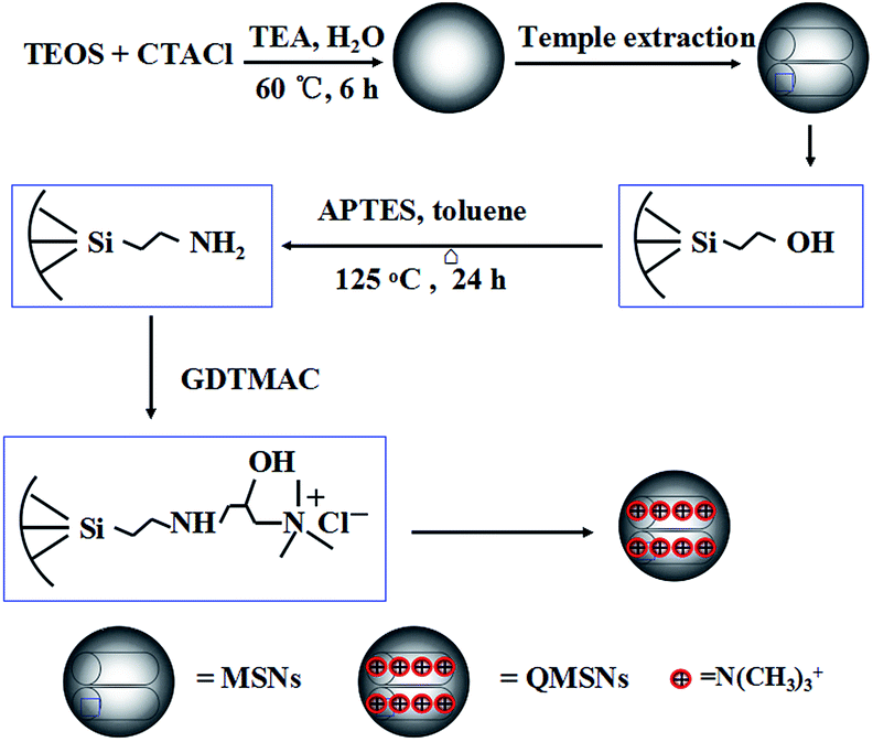
In this work, we report a series of novel organic–inorganic composite AEMs based on quaternized polysulfone (QPSU) and quaternized mesoporous silica nanoparticles (QMSNs) prepared via a simple blending method. The mesoporous silica nanoparticles (MSNs) with a diameter of about 45 nm were functionalized with APTES to form MSNs–NH2, and then QMSNs were prepared by epoxide ring opening reaction between the free amino groups of APTES and glycidyltrimethylammonium chloride (GDTMAC). Polysulfone was chloromethylated to act as the matrix of the composite AEMs. Then, a certain content of QMSNs was incorporated into the chloromethylated PSU to prepare the composite AEMs. The QMSNs were utilized to increase the IEC, ion conductivity and water uptake of the composite AEMs due to the hydrophilic quaternary ammonium groups. The influences of the feed ratio of QMSNs on membrane properties, such as hydrophilicity, thermal stability and electrical performances will be fully discussed.
2. Experimental
2.1 Materials
Polysulfone (PSU, Mw = 58000) was purchased from Sigma-Aldrich. Cetyltrimethyl ammonium chloride (CTACl), triethanolamine (TEA), tetraethoxysilane (TEOS), 3-aminopro-pyltrimethoxysilane (APTES) and glycidyltrimethylammonium chloride (GDTMAC) were obtained from Aladdin. Chloromethyl methyl ether (CMME) was purchased from Linyi Fude Fine Chemical. All other reagents were obtained from Shanghai Chemical Reagent Plant and used without further purifications.
2.2 Chloromethylation of polysulfone
The chemical structure of chloromethylated polysulfone (CMPSU) is given in Scheme 1 and the CMPSU was prepared as the following procedure: 20 g PSU was dissolved in 180 mL chloroform containing 3.41 g zinc chloride (ZnCl2) at 45 °C and then a clear polymer solution was obtained, after that 25 mL CMME was slowly added into the polymer solution with constant stirring. The reaction was allowed for 10 h at 45 °C to get a dark viscous mixture, and then the chloromethylated polymer was precipitated in methanol to remove the unreacted reagents and solvent. The product was further washed with abundant water and methanol several times until the pH is neutral. The final product was dried at 50 °C in vacuum for 12 h.
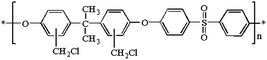 |
| | Scheme 1 Structure of chloromethylated polysulfone (CMPSU). | |
2.3 Preparation of quaternized mesoporous silica
2.3.1 Preparation of mesoporous silica nanoparticles (MSNs). The unmodified mesoporous silica nanoparticles (MSNs) were prepared according to the procedure described in the literature.50 2.52 g CTACl was dissolved in a mixed solution of 10.4 mL deionized water and 10.5 mL ethanol, then 64 mL deionized water was added under stirring for 10 min at room temperature and a clear solution was obtained. After that, 4.13 mL TEA was added and further stirred for 30 min to dissolve the TEA completely, resulting in the pH value of 11.3 to 11.6. Usually, 40 mL of the above solution in a three-necked flask in an oil bath was heated to 60 °C. When the temperature stabilized, 2.9 mL TEOS was added dropwise within 2–3 min under constant stirring and the solution turned into milk-white after about 10 min of stirring. The reaction was finished after 2 h and the solution was cooled to room temperature, meanwhile the pH value decreased to 9.3. The resulting milk-white as-synthesized product was collected by centrifugation at 9500 rpm for 15 min and washed with deionized water for three times. Template extraction was performed as follows: one gram of sample was treated three times with 100 mL of extraction solution (15 mL conc. HCl mixed with 120 mL ethanol) by ultrasonication in ice bath for 30 min, afterwards the product (MSNs) was further washed with water and methanol twice respectively and finally dried at room temperature in vacuum for 24 h.
2.3.2 Synthesis of amino-functionalized mesoporous silica nanoparticles (MSNs–NH2). The above dried unmodified MSNs were dispersed in toluene by ultrasonication for 5 min before APTES was added into the suspension. The molar ratio of MSNs, APTES and toluene was fixed at 5:0.8:500, and the reaction was performed under reflux (125 °C) for 24 h under dry nitrogen protection. The amino-functionalized MSNs (MSNs–NH2) were obtained by centrifugation and washed with toluene and ethanol twice, respectively, and at last dried at room temperature in vacuum to obtain the dry power.
2.3.3 Preparation of quaternized mesoporous silica nanoparticles (QMSNs). QMSNs were prepared by epoxide ring opening reaction. The MSNs–NH2 were dispersed in degassed water by ultrasonication, then GDTMAC was added and the suspension was transferred into a three-necked flask under a nitrogen atmosphere and kept stirring for 3 h at room temperature, and then heated at 80 °C for 6 h. The obtained QMSNs were collected by centrifugation and washed by water and ethanol twice, respectively, and at last dried at room temperature in vacuum to obtain the sickly white power.
2.4 Preparation of composite membranes
The composite membranes were prepared via a simple solution casting method and the typical preparation procedure was as follows: a certain amount of CMPSU was dissolved in DMF with stirring at 45 °C for 6 h, and different proportions (0, 5, 10, 15, and 20 wt%) of QMSNs were ultrasonicated in DMF and added into the CMPSU solution with stirring for 24 h. The above solutions were poured onto a clean glass dish and dried at 45 °C for 8 h, and then dried in a vacuum oven at 70 °C for 12 h to obtain a composite membrane. The composite membrane was quaternized by immersion in a 33 wt% trimethylamine aqueous solution at room temperature for 48 h and washed thoroughly with deionized water, and then alkalization in a 1 M potassium hydroxide aqueous solution at room temperature for 48 h, followed by washing with water for several times. It should be pointed out that it's difficult to exclude CO2 during the characterizations, so all the membranes storing in water were converted to bicarbonate form by exposing to ambient air for 4 days.10
2.5 Measurements
2.5.1 Instrumental characterizations. Fourier transform infrared (FTIR) spectra were recorded on a Magna 560 FTIR spectrometer. Proton NMR (1H-NMR) spectra were recorded on a Bruker Avance 500 MHz NMR using deutrated chloroform (CDCl3) or deutrated dimethyl sulfoxide (DMSO-d6) as the solvent. The morphology characterizations were carried out by a JEM-2100F transmission electron microscope (TEM). Nitrogen (N2) adsorption/desorption isotherms were measured by using a Nova 1000 analyzer with nitrogen. The samples are dried at 160 °C for 6 h in vacuum, the analysis adsorptive is liquid nitrogen with the analysis bath temperature at −196 °C. The equilibration interval is 10 s. Surface areas were calculated by the Brunauer–Emmett–Teller (BET) method and the pore size was calculated by the Barrett–Joyner–Halenda (BJH) methods. Thermogravimetric analysis (TGA) was carried out utilizing a Perkin-Elmer TGA-2 thermogravimetric analyzer by heating the samples from room temperature to 800 °C with a heating rate of 10 °C min−1 under nitrogen atmosphere. The fractured surface morphologies of the composite membrane obtained by brittle breakage in liquid nitrogen were investigated using scanning electron microscopy (SEM) (XL-30 ESEM FEG, FEI Company). The mechanical properties of the membranes were measured with an instron model 1122 at room temperature and 50% RH and at an elongation rate of 5 mm min−1.
2.5.2 Ion exchange capacity, water uptake and swelling ratio. The ion exchange capacity (IEC) was performed by Mohr titration. A piece of sample (about 0.2 g) was soaked into 0.5 M HCl solution for 24 h to ion exchange, then washed with deionized water completely and the Cl− form membrane was obtained. The membrane was immersed in 50 mL 0.2 M NaNO3 for 8 h for three times, respectively. And then the NaNO3 solution were collected respectively and titrated with 0.1 M AgNO3 using K2CrO4 as the colorimetric indicator. The weight of dry membrane was obtained by drying the sample at 80 °C in vacuum. IEC (mmol g−1) value of membrane was calculated using the formula:
where Wdry (g) is the dry weight of the sample, V (mL) is the titrated volume of AgNO3 solution and C (mol L−1) is the concentration of AgNO3 solution.The fully hydrated membranes were taken out of water and wiped quickly to remove surface liquid and weighed immediately. This measurement was repeated after sufficient soaking time to rehydrate the samples to get a repeatable weight of wet membrane. Then the samples were dried at 80 °C in vacuum for 10 h and weighed again. The water uptake can be obtained by the following equation:
| Water uptake (WU) = [(Wwet − Wdry)/Wdry] × 100% |
where
Wwet and
Wdry (g) are the weight of the wet membrane and dried membrane, respectively.
The swelling ratio of membranes was investigated by soaking the samples in deionized water at room temperature for 24 h. The changes of length (ΔL) and thickness (ΔT) were calculated from the following equation:
| ΔL = [(Lwet − Ldry)/Ldry] × 100% |
| ΔT = [(Twet − Tdry)/Tdry] × 100% |
where
Lwet and
Ldry (cm) are the length of the wet and dry membranes, respectively.
Twet and
Tdry (μm) are the thickness of the wet and dry membranes, respectively.
2.5.3 Ionic conductivity. The ionic conductivity of full hydration membranes (4 cm × 1 cm) at 25, 40, 60 and 80 °C were measured using normal four-probe conductivity cell attached with AC impedance spectroscopy of electro-chemical work station and the frequency ranged from 1 Hz to 100 kHz. The ionic conductivity σ was determined from the following formula:
where σ (S cm−1) is the ionic conductivity, L (cm) is the distance between the two electrodes, A (cm2) is the cross-sectional area of the membrane and R (Ω) is the AC resistance of the membrane.
2.5.4 Alkaline resistance and oxidative stability. The composite membranes were immersed in 1 M KOH solution at 60 °C for 240 h and washed thoroughly with deionized water to remove the residual KOH, and the IEC and bicarbonate conductivity of the samples were measured to evaluate the effect of the hot alkaline circumstance. During the testing, the remaining weight was measured every 24 h. After 120 h immersion in KOH at 60 °C, the IEC and bicarbonate conductivity at 25 °C and 80 °C were tested, respectively.Oxide stability was determined by immersing the composite membranes (1 cm × 3 cm) in Fenton's reagent (4 ppm Fe2+ in 3% H2O2) at 80 °C for 120 h under stirring. The remaining weight was measured every 10 h to evaluate the degradation process on the samples.
3. Results and discussion
3.1 Characterization of PSU, CMPSU and QPSU
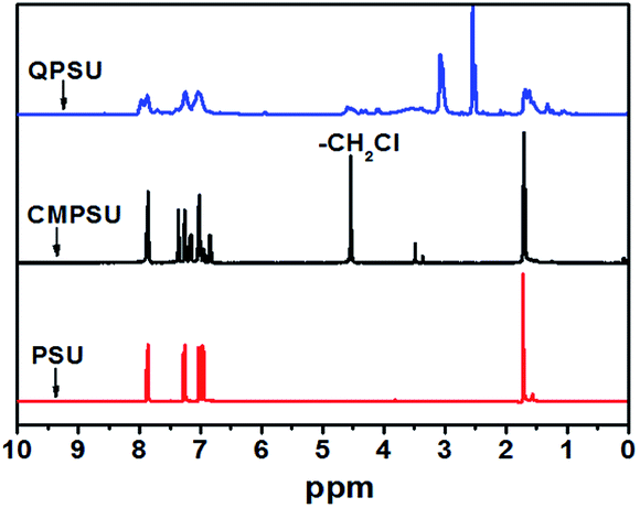
The 1H NMR spectra of PSU, CMPSU and QPSU are shown in Fig. 1, and the structure of the CMPSU is shown in Scheme 1. For both the 1H NMR spectra of PSU, CMPSU and QPSU, the chemical shifts from 7.86 ppm to 6.85 ppm are the multi Hs of the phenyl groups, and the peaks at 1.72 ppm are the Hs of the methyl groups. Compared with the spectra of PSU and CMPSU, the newly formed sharp peak at 4.56 ppm of CMPSU attributed to the characteristic chemical shift of the chloromethyl group confirms the successful formation of CMPSU,11,12 the number of the tethered chloromethyl groups is calculated as 1.6 from the integration of chemical shifts of chloromethyl at 4.56 ppm and phenyl groups at 7.86 ppm. For the spectrum of the QPSU, the new peaks at 4.54 ppm and 3.0 ppm are the methylene and methyl groups in the quaternized ammonio groups,50 the sharp peak at 2.5 ppm is the characteristic chemical shift of DMSO-d6, and the results reveals that the CMPSU and QPSU were successfully prepared.
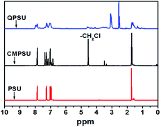 |
| | Fig. 1 1H NMR spectra of PSU, CMPSU and QPSU. | |
3.2 Characterization of QMSNs
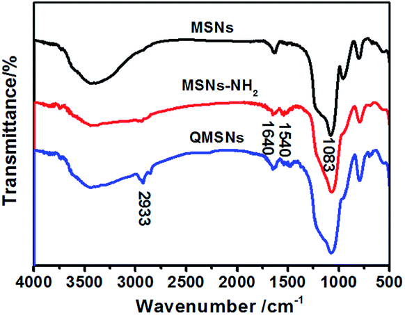
The synthetic route for QMSNs is shown in Scheme 2. The unmodified mesoporous silica nanoparticles were prepared by the hydrolysis of tetraethoxysilane by using CTACl as template at a lower pH circumstance,51 and then the template agents were removed to form MSNs. After that, the MSNs were functionalized with APTES, leaving free amino groups on the MSNs–NH2, and QMSNs were prepared by epoxide ring opening reaction between the amino groups of the MSNs–NH2 and the GDTMAC. The FT-IR spectra of MSNs, MSNs–NH2 and QMSNs are shown in Fig. 2. There is a strong and broad absorption corresponding to Si–O–Si bonds at 1000–1200 cm−1 in the spectra of MSNs, MSNs–NH2 and QMSNs. Compared with the FT-IR spectrum of MSNs, the characteristic asymmetric bending peaks of –NH2 on MSNs–NH2 (ref. 52 and 53) in the region of 1380–1560 cm−1 can be clearly observed though the N–H stretching peaks at 3380 cm−1 and 3310 cm−1 are overlapped with the O–H stretching peaks of silanol groups in the range of 3200–3600 cm−1, which indicates that the amino groups have been successfully bonded on the inner surface of mesoporous silica. For the FT-IR spectrum of QMSNs, the stretching vibrations at 2933, 1610 and 1478 cm−1 are clearly presented, confirming the existence of the quaternary ammonium groups in the QMSNs.17,18
 |
| | Scheme 2 Synthetic reaction of QMSNs. | |
 |
| | Fig. 2 FT-IR spectra of MSNs, MSNs–NH2 and QMSNs. | |
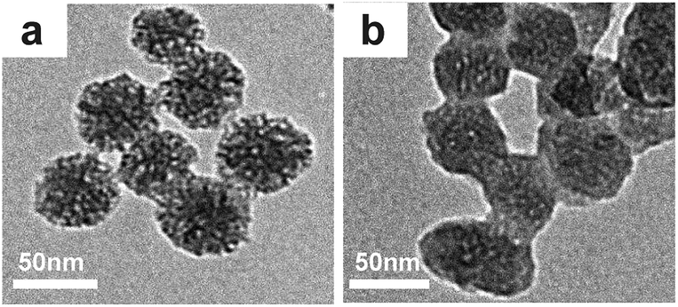
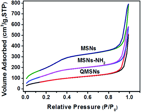
It has been well documented that the mesoporous structures have a great effect on the properties of membranes. So the morphologies in the MSNs and QMSNs were observed through TEM (Fig. 3). It can be seen that on the whole, the average diameters of the particles in both MSNs and QMSNs are about 45 nm with a wormhole arrangement of pores. In order to further study the mesoporous structures among the MSNs, MSNs–NH2 and QMSNs, liquid nitrogen isotherm measurements were used to characterize the pore volume, pore size, and surface area of the MSNs, MSNs–NH2 and QMSNs. The nitrogen adsorption–desorption isotherms of these samples are shown in Fig. 4. It can be found that the adsorbed volume all increases with the increasing of the relative pressure among the three samples which conforms well to the type-IV isotherms according to the IUPAC classification. As listed in Table 1, it can be seen that the surface area, desorption cumulative volume and average pore diameter decrease clearly from 792 m2 g−1, 0.86 cm3 g−1 and 2.2 nm, respectively in MSN to 530 m2 g−1, 0.63 cm3 g−1 and 1.9 nm, respectively in MSNs–NH2, and to 293 m2 g−1, 0.50 cm3 g−1 and 1.7 nm, respectively in QMSNs, which is attributed to the different sorts of intermolecular forces among the MSNs, MSNs–NH2 and QMSNs and this also composes the indirect evidence for the formation of MSNs–NH2 and QMSNs. It is noteworthy that although the surface area, desorption cumulative volume and average pore diameter of QMSNs reduce as compared with that of non-functionalized MSNs, QMSNs still have ample surface area and distribute uniformly with the mesoporous structure (Fig. 3b and Table 1) which will take a great effect on the properties of the composite AEMs (will be demonstrated later).
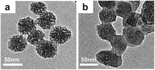 |
| | Fig. 3 TEM images of MSNs (a) and QMSNs (b). | |
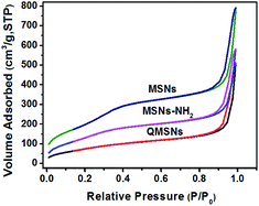 |
| | Fig. 4 Nitrogen adsorption–desorption isotherms of MSNs, MSNs–NH2 and QMSNs. | |
Table 1 Textural properties of MSNs, MSNs–NH2 and QMSNs
| Sample |
SBETa (m2 g−1) |
Vtb (cm3 g−1) |
DBJHc (nm) |
| BET surface. Total pore volume. Average pore diameter calculated using BJH method. |
| MSNs |
792 |
0.86 |
2.2 |
| MSNs–NH2 |
530 |
0.63 |
1.9 |
| QMSNs |
293 |
0.50 |
1.7 |
3.3 Characterization of composite membranes
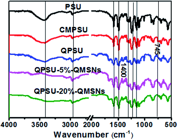
3.3.1 FT-IR and microstructure analysis. The CMPSU was successfully prepared with proper degree of chloromethylation as demonstrated in Fig. 1. The composite membranes with different proportions of QMSNs were prepared via a simple blending method, followed by quaternization, alkalization and being exposed to the air to get the bicarbonate form. The FT-IR spectra of PSU, CMPSU, QPSU, QPSU-5%–QMSNs and QPSU-20%–QMSNs are shown in Fig. 5. The broad absorption bands at 3400 cm−1 are attributed to the stretching vibration of O–H, which is due to the presence of water. The peak at 2960 cm−1 is contributed to the aromatic –CH stretching, while the sharp peaks at 1590, 1510 and 1490 cm−1 are the skeletal vibrations of the aromatic hydrocarbons. The strong peak around 1240 cm−1 is assigned to the asymmetric vibration of the ether linkage. The absorption peaks at 1290 and 1150 cm−1 represent the asymmetric and symmetric stretching vibration of the O![[double bond, length as m-dash]](https://www.rsc.org/images/entities/char_e001.gif) SO. All the characteristic peaks mentioned above are ascribed to the PSU backbone and arise on all the FT-IR spectra of the samples. The peak at 745 cm−1 for CMPSU can be assigned to the C–Cl stretching vibration, and its absorption intensity has an obvious increase as compared with that of PSU, proving that the PSU has been chloromethylated successfully.36 In addition, comparing the FT-IR spectra of CMPSU and QPSU, the absorption bands of QPSU between 1400 cm−1 and 1360 cm−1 have been improved to some extent, indicating that the quaternary ammonium groups are introduced into the polymers. When the QMSNs are introduced into the polymers, the FT-IR spectra of the composite membranes are similar to that of QPSU, except that the absorption bands of Si–O–Si at 1000–1200 cm−1 gradually increase with the increasing content of QMSNs, suggesting an increasing content of QMSNs are incorporated into the membranes.
SO. All the characteristic peaks mentioned above are ascribed to the PSU backbone and arise on all the FT-IR spectra of the samples. The peak at 745 cm−1 for CMPSU can be assigned to the C–Cl stretching vibration, and its absorption intensity has an obvious increase as compared with that of PSU, proving that the PSU has been chloromethylated successfully.36 In addition, comparing the FT-IR spectra of CMPSU and QPSU, the absorption bands of QPSU between 1400 cm−1 and 1360 cm−1 have been improved to some extent, indicating that the quaternary ammonium groups are introduced into the polymers. When the QMSNs are introduced into the polymers, the FT-IR spectra of the composite membranes are similar to that of QPSU, except that the absorption bands of Si–O–Si at 1000–1200 cm−1 gradually increase with the increasing content of QMSNs, suggesting an increasing content of QMSNs are incorporated into the membranes.
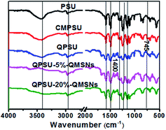 |
| | Fig. 5 FT-IR spectra of PSU, CMPSU, QPSU, QPSU-5%–QMSNs and QPSU-20%–QMSNs. | |
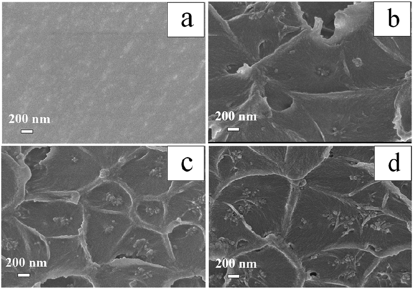
Scanning electron microscopy (SEM) is used to investigate the internal microstructure of the QPSU membrane and the composite membranes with different contents of QMSNs. Fig. 6 shows the images of the cross-section of different membranes. The cross-section of the pristine QPSU membrane presents a relatively smooth surface without any cracks or pinholes, indicating the formation of a high-quality membrane. When QMSNs are incorporated into the matrix, the cross-section of the composite membranes become roughness, and some aggregation of nanoparticles can be distinctly observed. With the increasing proportion of QMSNs filled in the composite membranes, the aggregation of the QMSNs become more evident and the size of the gather of QMSNs also grow in size. The morphologies of all of the composite members (Fig. 6b–d) containing up to 20 wt% QMSNs retain integrity and homogeneity without obvious microphase separation which indicates that there exists a favorable interaction between the inorganic QMSNs and the organic QPSU phases via weak bonds, such as van der Waals, hydrogen and ionic interactions. It should be pointed that although the composite membranes exhibit integrity and homogeneity on the whole, it is inevitable that the aggregation of the QMSNs in the composite membranes with high content of QMSNs will take place (Fig. 6c and d).
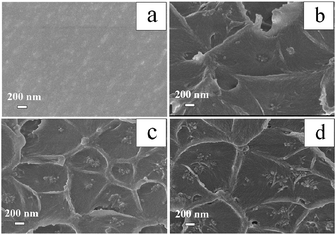 |
| | Fig. 6 SEM images of QPSU (a), QPSU-5%–QMSNs (b), QPSU-10%–QMSNs (c) and QPSU-20%–QMSNs (d). | |
3.3.2 Ion exchange capacity (IEC), water uptake (WU) and swelling ratio. Table 2 illustrates the IEC values, water uptake (WU) and swelling ratios of QPSU and the composite membranes with different content of QMSNs at 60 °C. The IEC value of the QMSNs is 1.95 mmol g−1, which is higher than that of the pristine QPSU membrane. It can be found that the IECs of the QPSU–QMSNs composite members are in the range of 1.69–1.73 mmol g−1, which values are higher than that (1.68 mmol g−1) of the pristine QPSU membrane. This result is attributed to the increase of the QMSNs contents in the composite membranes because the IEC values always indicate the concentration of quaternary ammonium groups in the membranes. The WU values of the composite membranes increase with the increasing content of the QMSNs, and all the membranes exhibit higher WU abilities at higher temperature, which can be attributed to the hygroscopic and water retention of the quaternary ammonium ions within the QMSNs. In addition, the high surface area of the mesophase structures can increase the content of absorption water and the inorganic network structure of QMSNs can reduce the mobility of the polymer chain and free volume so that the absorbed water can be limited within the composite membranes which all lead to an increased WU.54 As listed in Table 2, the swelling ratios of all the membranes are relatively low ranging from 10.7% to 6.5% and decrease clearly with increasing QMSNs content compared with that of pristine QPSU membrane, which indicates that the incorporation of inorganic fillers is a desirable method to enhance the dimensional stabilities of the composite membranes.
Table 2 Thickness, size, IEC, WU, swelling ratio and bicarbonate conductivity of different membranes
| Membrane |
Thickness (μm) |
Size (cm × cm) |
IECa (mmol g−1) |
WU (%) |
Swelling ratio (%)b |
σHCO3− (mS cm−1) |
| 25 °C |
60 °C |
ΔT |
ΔL |
25 °C |
80 °C |
| The samples were measured at room temperature. The samples were measured at 60 °C. |
| QPSU |
60 |
7.0 × 6.6 |
1.68 |
7.0 |
13.3 |
9.8 |
10.7 |
4.69 |
11.80 |
| QPSU-5%–QMSNs |
63 |
7.0 × 6.4 |
1.69 |
9.9 |
14.3 |
8.6 |
9.3 |
5.47 |
15.15 |
| QPSU-10%–QMSNs |
63 |
6.8 × 6.6 |
1.72 |
11.0 |
16.6 |
7.8 |
7.9 |
5.93 |
15.40 |
| QPSU-15%–QMSNs |
62 |
6.8 × 6.2 |
1.72 |
12.1 |
25.5 |
6.9 |
7.3 |
7.31 |
20.36 |
| QPSU-20%–QMSNs |
65 |
6.7 × 6.0 |
1.73 |
12.3 |
27.7 |
6.5 |
7.2 |
6.23 |
13.62 |
3.3.3 Ionic conductivity. The ionic conductivity of the membranes is particularly important and plays a crucial role in fuel cell performance. Because OH− can be quickly neutralized on exposing to air due to the rapid absorption of CO2, the conductivities of the membranes will steadily decline in the 3–4 days after the membranes change into the OH− form by ion-exchange process. To get a stable value, all the membranes storing in water were exposed to ambient air for 4 d to obtain the bicarbonate form. The ionic conductivities of different membranes are listed in Table 2 and plotted as a function of temperature in Fig. 7. It can be found that the ionic conductivities of all the membranes show the linear expansion with increasing temperature, which can be ascribed to that high temperature would not only make the ions and molecules diffuse easier but also magnify their free volume in the composite membranes.10 In general, the ionic conductivity will increase with increasing temperature for the ionic conductive membranes.
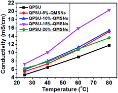 |
| | Fig. 7 Relation between temperature and bicarbonate conductivity of different membranes. | |
Table 2 and Fig. 7 also show the effects of the QMSNs content on the ionic conductivity of the composite membranes. When the content of QMSNs in composite membranes is below 15 wt%, the anion conductivities of the composite membranes increase with the increasing content of QMSNs. That is to say, the bicarbonate conductivities of the pristine QPSU membrane are 4.69 mS cm−1 at 25 °C and 11.80 mS cm−1 at 80 °C, respectively, while the conductivities of QPSU-15%–QMSNs membrane are 7.31 mS cm−1 at 25 °C and 20.36 mS cm−1 at 80 °C, respectively, showing nearly a twofold increase. The results indicate that the incorporation of the QMSNs is an effective method to greatly improve the bicarbonate conductivity which is mainly due to the ability of hydrated QMSNs providing the interconnected ionic transportation channels for the ions.21 Otherwise, the fact that the water uptake and IEC increase with increasing QMSNs can constitute another reason for the improvement of the bicarbonate conductivity in QPSU–QMSNs composite membranes. However, when the content of QMSNs reaches 20 wt% for QPSU-20%–QMSNs membrane, the bicarbonate conductivities decrease to 6.23 mS cm−1 at 25 °C and 13.62 mS cm−1 at 80 °C, respectively. This may be attributed to the following reasons. One is that when the content of QMSNs reaches 20 wt%, the “block effect” starts to predominate, which is mainly due to the aggregation of the QMSNs within the composite membranes.39,55 The other is that when the content of QMSNs reaches 20 wt%, the number of the interconnected ion transportation channels will drop rapidly. Consequently, the bicarbonate conductivity of the composite membrane reduces. To sum up, it is necessary to point out that the appropriate content of QMSNs can improve the bicarbonate conductivity more evidently.
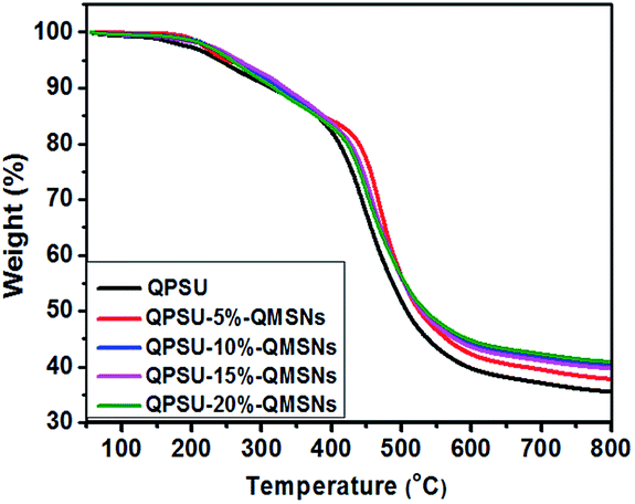
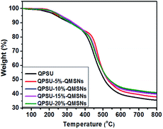
3.3.4 Thermal and mechanical properties. The thermal stability of the membranes is an important prerequisite for the use of fuel cell. As shown in Fig. 8, the TGA curves of the membranes are divided into three main stages. The initial weight loss from 50 to 170 °C is contributed to the release of the residual solvent (DMF) and the absorbed water. The second weight loss around 170 °C is due to the decomposition of quaternary ammonium groups of samples. The third weight loss above 400 °C is corresponding to the degradation of polymer main chains. All the membranes exhibit almost the same degradation trends though the composite membranes show higher thermal stability than the pristine QPSU at this stage. In addition, the residue of the composite membranes at 800 °C is higher than that of the QPSU membrane. In the preparation of the AEMs, high temperature is adopted to remove the water and solvent within the membranes, and some cross-linking may take place at the same time. During the TGA measurement, the organic phase may melt and permeate into the holes of the inorganic phase and wrapped up by the inorganic phase at high temperature. When the samples are heated to 400 °C, the decomposition of the organic phase takes place, but some organic phase can't be taken away by N2 because of the wrap and the interaction between the organic phase and inorganic phase, so the remain of the composite membranes is high. The remain of the pristine QPSU membrane is not zero at 800 °C, which is according with some reports in the AEMs study.36,37,56 In conclusion, all the membranes show the same degradation trend and the TGA remains may be not in agreement with inorganic loading in the composites.
 |
| | Fig. 8 TGA curves of different membranes. | |
The mechanical properties of the composite membranes were measured using a tensile testing instrument at room temperature under dry conditions and the results are listed in Table 3. There is an increase in the Young's modulus and tensile strength of the composite membranes containing QMSNs as compared with that of pristine QPSU membrane, ranging from 1990 MPa to 2250 MPa. All the membranes show the elongation at break between 4.4% and 6.8%. In general, the composite membranes containing different proportions of QMSNs are obtained without sacrificing the mechanical properties and all the membranes show acceptable mechanical properties.
Table 3 Mechanical properties of different membranes
| Membrane |
Young's modulus (MPa) |
Tensile strength (MPa) |
Elongation at break (%) |
| QPSU |
1990 |
72.0 |
6.8 |
| QPSU-5%-QMSNs |
2030 |
72.9 |
6.5 |
| QPSU-10%–QMSNs |
2060 |
73.2 |
6.0 |
| QPSU-15%–QMSNs |
2180 |
74.1 |
5.2 |
| QPSU-20%–QMSNs |
2250 |
75.7 |
4.4 |
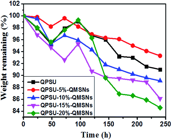
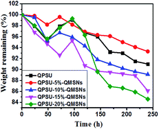
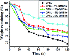
3.3.5 Alkaline resistance and oxidative stability. The stability of the AEMs is one of the most important properties especially in the hot alkaline conduction and it involves the stability of the charged groups and the polymer matrix.13 It is generally known that the quaternary ammonium groups are relatively unstable in alkaline condition, and the degradations, including direct nucleophilic displacement and Hofmann elimination etc. may take place.54 To evaluate the stability of the membranes, all the membranes were immersed in 1 M KOH aqueous solution at 60 °C, and the weight was taken every 24 h, and then the IEC and bicarbonate conductivity at 25 °C and 80 °C were measured after 120 h. The weight remaining of the different membranes are shown in Fig. 9 and the IEC, bicarbonate conductivity are listed in Table 4. The initial increase in weight in the first 72 or 96 h may be attributed to that the swelling of the membranes overwhelms the degradation of the membranes.37 Then the membranes present a declining trend in weight, indicating the degradation has taken place. The weight losses of the composite membranes range from 6.8% to 15.5% at the 240 h of testing, and the weight loss of the composite membranes is higher than the pristine QPSU membrane, which may be contributed to two reasons. One is that when the inorganic fillers are incorporated into the matrix, the interface void become bigger and the NaOH can more easily permeate into the samples, then the degradation becomes faster. The other is that when the surface organic phase of the composite membranes break down, the interaction between the QPSU and the QMSNs become weaker, and some QMSNs can be dissolved in the 1 M NaOH, so the weight lose of the composite membranes is higher than the pristine QPSU membrane. After 120 h of immersing in 1 M KOH, the bicarbonate conductivity of the membranes varies between 4.15 mS cm−1 and 5.51 mS cm−1 at 25 °C, and at 80 °C the bicarbonate conductivity varies between 8.36 mS cm−1 and 11.08 mS cm−1. In addition, the IEC also presents a depressed trend, and the IEC value ranges from 1.38 to 1.28 mmol g−1 after alkaline resistance tests and it can be inferred that the membranes show acceptable alkaline resistance.36
 |
| | Fig. 9 Weight remaining of different membranes in 1 M NaOH solution at 60 °C. | |
Table 4 IEC and bicarbonate conductivity at 25 °C and 80 °C of different membranes after inmmersion in 1 M NaOH at 60 °C for 120 h
| Membrane |
IEC (mmol g−1) |
σHCO3− (mS cm−1) |
| 25 °C |
80 °C |
| QPSU |
1.28 |
4.15 |
9.00 |
| QPSU-5%-QMSNs |
1.36 |
4.51 |
9.22 |
| QPSU-10%–QMSNs |
1.31 |
4.34 |
8.36 |
| QPSU-15%–QMSNs |
1.28 |
5.32 |
10.5 |
| QPSU-20%–QMSNs |
1.38 |
5.51 |
11.8 |
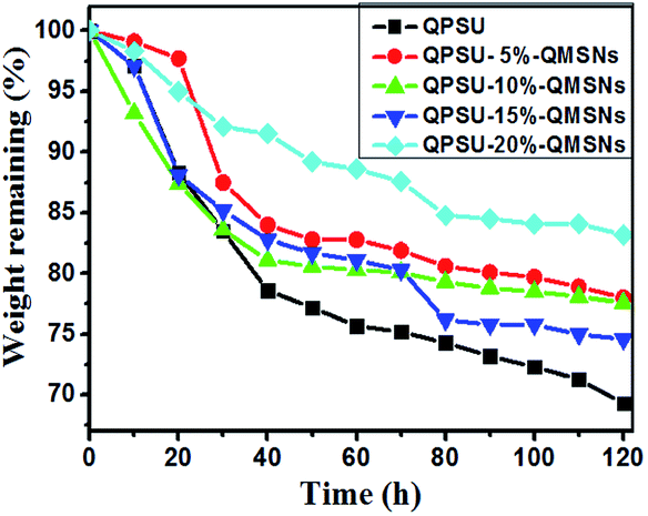
It is essential for the AEMs to have a good oxide stability in the harsh environment and then the Fenton's reagent is adopted to simulate and accelerate the harsh operation environment, in which the formed *OH and *OOH radicals from H2O2 can cause the degradation of the AEMs.36 All the membranes are immersed into a hot Fenton's reagent (4 ppm Fe2+ in 3% H2O2) at 80 °C under stirring and the Fenton's reagent was refreshed every 4 h. The weight was taken every 10 h and the values are presented in Fig. 10. The results show that the weights of all the membranes decrease with the increasing testing time and the weight losses of the membranes range from 16.8% to 30.7%. Meanwhile, it can also be confirmed from Fig. 10 that the oxidative stability of the composite membranes is better than that of the QPSU membrane without QMSNs. Hence, the incorporation of the QMSNs can improve the oxidative stability of the membranes. It is worth to point out that all the membranes did not show any physical deformation in the first 8 h.
 |
| | Fig. 10 Degradation of different membranes in 3% H2O2/4 ppm Fe2+ solution at 80 °C. | |
4. Conclusions
Quaternized mesoporous silica nanoparticles (QMSNs) with an average diameter about 45 nm were prepared, and then different proportions of QMSNs were incorporated into the aryl polymers to fabricate a series of novel composite alkaline anion exchange membranes by the simple casting procedure. The resulted composite membranes show improved properties than the pristine QPSU membrane. Especially, the QPSU-15%–QMSNs membrane shows nearly a twofold increase of bicarbonate conductivity in the QPSU membrane without obviously sacrificing the mechanical properties. With the increasing content of QMSNs, the IEC and WU which can also enhance the bicarbonate conductivities increase while the swelling ratios decrease rapidly in the QPSU–QMSNs membranes. In addition, the improved thermal properties, good morphologies without phase separation, acceptable alkaline resistance and oxide resistance also suggest that the prepared composite membranes are adequate in the AEMFC applications. The functionalized MSNs are a promising material for the fabrication of composite AEMs, and the incorporation of proper content of QMSNs have obviously improved the properties, especially the bicarbonate conductivity as compared with the pristine QPSU membrane. In conclusion, our strategy can open up a new perspective in the design and preparation of novel organic–inorganic composite anion exchange membranes with high performance for alkaline fuel cell by introduction of the functionalized MSNs into the polymers.
Acknowledgements
We would like to appreciate the financial support of the National Natural Science Foundation of China (20704004, 21074019).
Notes and references
- M. A. Hickner, H. Ghassemi, Y. S. Kim, B. R. Einsla and J. E. McGrath, Chem. Rev., 2004, 104, 4587 CrossRef CAS.
- S. Lu, J. Pan, A. Huang, L. Zhuang and J. Lu, Proc. Natl. Acad. Sci. U. S. A., 2008, 105, 20611 CrossRef CAS.
- T. Sakamoto, K. Asazawa, K. Yamada and H. Tanaka, Catal. Today, 2011, 164, 181 CrossRef CAS PubMed.
- K. B. Liew, W. R. W. Daud, M. Ghasemi, J. X. Leong, S. S. Lim and M. Ismail, Int. J. Hydrogen Energy, 2014, 39, 4870 CrossRef PubMed.
- J. Zhou, M. Ünlü, I. Anestis-Richard and P. A. Kohl, J. Membr. Sci., 2010, 350, 286 CrossRef CAS PubMed.
- M. A. Hickner, A. M. Herring and E. B. Coughlin, J. Polym. Sci., Part B: Polym. Phys., 2013, 51, 1727 CrossRef CAS PubMed.
- G. Merle, M. Wessling and K. Nijmerjer, J. Membr. Sci., 2011, 377, 1 CrossRef CAS PubMed.
- M. Tanaka, K. Fukasawa, E. Nishino, S. Yamaguchi, K. Yamada, H. Tanaka, B. Bae, K. Miyatake and M. Watanabe, J. Am. Chem. Soc., 2011, 133, 10646 CrossRef CAS PubMed.
- A. H. N. Rao, R. L. Thankamony, H. J. Kim, S. Nam and T. H. Kim, Polymer, 2013, 54, 111 CrossRef CAS PubMed.
- J. Yan and M. A. Hickner, Macromolecules, 2010, 43, 2349 CrossRef CAS.
- F. Zhang, H. Zhang and C. Qu, J. Mater. Chem., 2011, 21, 12744 RSC.
- G. Wang, Y. Weng, D. Chu, R. Chen and D. Xie, J. Membr. Sci., 2009, 332, 63 CrossRef CAS PubMed.
- C. Zhao, W. Ma, W. Sun and H. Na, J. Appl. Polym. Sci., 2014, 131, 40256 Search PubMed.
- Y. Wu, C. Wu, Y. Li, T. Xu and Y. Fu, J. Membr. Sci., 2010, 350, 322 CrossRef CAS PubMed.
- C. Yang, S. Chiu, S. Kuo and T. H. Liou, J. Power Sources, 2012, 199, 37 CrossRef CAS PubMed.
- E. Wang, T. Zhao and W. Yang, Int. J. Hydrogen Energy, 2010, 35, 2183 CrossRef CAS PubMed.
- S. Singh, A. Jasti, M. Kumar and V. K. Shahi, Polym. Chem., 2010, 1, 1302 RSC.
- B. P. Tripathi, M. Kumar and V. K. Shahi, J. Membr. Sci., 2010, 360, 90 CrossRef CAS PubMed.
- C. Yang, J. Membr. Sci., 2007, 288, 51 CrossRef CAS PubMed.
- S. Sang, J. Zhang, Q. Wu and Y. Liao, Electrochim. Acta, 2007, 52, 7315 CrossRef CAS PubMed.
- W. Pan, S. Lue, C. Chang and Y. Liu, J. Membr. Sci., 2011, 376, 225 CrossRef CAS PubMed.
- Y. Ye, M. Cheng, X. Xie, J. Rick, Y. Huang, F. Chang and B. J. Hwang, J. Power Sources, 2013, 239, 424 CrossRef CAS PubMed.
- X. Yan, S. Gu, G. He, X. Wu and J. Benziger, J. Power Sources, 2014, 250, 90 CrossRef CAS PubMed.
- G. Wang, Y. Weng, J. Zhao, R. Chen and D. Xie, J. Appl. Polym. Sci., 2009, 112, 721 CrossRef CAS PubMed.
- G. Wang, Y. Weng, D. Chu, D. Xie and R. Chen, J. Membr. Sci., 2009, 326, 4 CrossRef CAS PubMed.
- M. Zhang, H. K. Kim, E. Chalkova, F. Mark, S. N. Lvov and T. C. Mike Chung, Macromolecules, 2011, 44, 5937 CrossRef CAS.
- O. D. Thomas, K. J. W. Y. Soo, T. J. Peckham, M. P. Kulkarni and S. Holdcroft, J. Am. Chem. Soc., 2012, 134, 10753 CrossRef CAS PubMed.
- T. Xu, Z. Liu, Y. Li and W. Yang, J. Membr. Sci., 2008, 320, 232 CrossRef CAS PubMed.
- N. Li, Y. Leng, M. A. Hickner and C. Wang, J. Am. Chem. Soc., 2013, 135, 10124 CrossRef CAS PubMed.
- S. Cheng, F. L. Beyer, B. D. Mather, R. B. Moore and T. E. Long, Macromolecules, 2011, 44, 6509 CrossRef CAS.
- L. Sun, J. Guo, J. Zhou, Q. Xu, D. Chu and R. Chen, J. Power Sources, 2012, 202, 70 CrossRef CAS PubMed.
- Q. Zeng, Q. Liu, I. Broadwell, A. Zhu, Y. Xiong and X. Tu, J. Membr. Sci., 2010, 349, 237 CrossRef CAS PubMed.
- J. Ni, C. Zhao, G. Zhang, Y. Zhang, J. Wang, W. Ma, Z. Liu and H. Na, Chem. Commun., 2011, 47, 8943 RSC.
- S. Lu, R. Xiu, X. Xu, D. Liang, H. Wang and Y. Xiang, J. Membr. Sci., 2014, 464, 1 CrossRef CAS PubMed.
- J. Hu, D. Wan, W. Zhu, L. Huang, S. Tan, X. Cai and X. Zhang, ACS Appl. Mater. Interfaces, 2014, 6, 4720 CAS.
- R. Vinodh, M. Purushothaman and D. Sangeetha, Int. J. Hydrogen Energy, 2011, 36, 7291 CrossRef CAS PubMed.
- X. Li, Y. Yu and Y. Meng, ACS Appl. Mater. Interfaces, 2013, 5, 1414 CAS.
- R. Vinodh and D. Sangeetha, J. Appl. Polym. Sci., 2013, 128, 1930 CAS.
- Q. Li, L. Liu, S. Liang, Q. Dong, B. Jin and R. Bai, RSC Adv., 2013, 3, 13477 RSC.
- J. Wu, C. Lo, L. Li, H. Li, C. Chang, K. Liao, C. Hu, Y. Liu and S. Lue, J. Power Sources, 2014, 246, 39 CrossRef CAS PubMed.
- R. I. Nooney, T. Dhanasekaran, Y. M. Chen, R. Josephs and A. E. Ostafin, Adv. Mater., 2002, 14, 529 CrossRef CAS.
- H. Kao, C. Liao, A. Palani and Y. Liao, Microporous Mesoporous Mater., 2008, 113, 212 CrossRef CAS PubMed.
- Y. Zhao, B. G. Trewyn, I. I. Slowing and S. Y. Lin, J. Am. Chem. Soc., 2009, 131, 8398 CrossRef CAS PubMed.
- Y. Tominaga, I. C. Hong, S. Asai and M. Sumita, J. Power Sources, 2007, 171, 530 CrossRef CAS PubMed.
- Y. Choi, Y. Kim, H. K. Kim and J. S. Lee, J. Membr. Sci., 2010, 357, 199 CrossRef CAS PubMed.
- Y. Lin, C. Yen, C. C. M. Ma, S. H. Liao, C. H. Lee, Y. H. Hsiao and H. P. Lin, J. Power Sources, 2007, 171, 388 CrossRef CAS PubMed.
- D. Liu, L. Geng, Y. Fu, X. Dai and C. Lü, J. Membr. Sci., 2011, 366, 251 CrossRef CAS PubMed.
- L. Geng, Y. He, D. Liu and C. Lü, J. Appl. Polym. Sci., 2012, 123, 3164 CrossRef CAS PubMed.
- L. Geng, Y. He, D. Liu, X. Dai and C. Lü, Microporous Mesoporous Mater., 2012, 148, 8 CrossRef CAS PubMed.
- M. Tanaka, M. Koike, K. Miyatake and M. Watanabe, Macromolecules, 2010, 43, 2657 CrossRef CAS.
- K. Möller, J. Kobler and T. Bein, Adv. Funct. Mater., 2007, 17, 605 CrossRef PubMed.
- S. Song, K. Hidajat and S. Kawi, Langmuir, 2005, 21, 9568 CrossRef CAS PubMed.
- X. Fu, X. Chen, J. Wang, J. Liu and X. Huang, Electrochim. Acta, 2010, 56, 102 CrossRef CAS PubMed.
- T. Fu, J. Wang, J. Ni, Z. Cui, S. Zhong, C. Zhao, H. Na and W. Xing, Solid State Ionics, 2008, 179, 2265 CrossRef CAS PubMed.
- C. Tseng, Y. Ye, M. Cheng, K. Kao, W. Shen, J. Rick, J. Chen and B. J. Hwang, Adv. Energy Mater., 2011, 1, 1220 CrossRef CAS PubMed.
- X. Li, J. Tao, G. Nie, L. Wang, L. Li and S. Liao, RSC Adv., 2014, 4, 41398 RSC.
|
| This journal is © The Royal Society of Chemistry 2015 |
Click here to see how this site uses Cookies. View our privacy policy here.