
 Open Access Article
 This Open Access Article is licensed under a Creative Commons Attribution-Non Commercial 3.0 Unported Licence
A strategy for synthesis of lipid nanoparticles using microfluidic devices with a mixer structure
Masatoshi
Maeki†
a,
Tatsuyoshi
Saito†
b,
Yusuke
Sato
c,
Takao
Yasui
de,
Noritada
Kaji
de,
Akihiko
Ishida
a,
Hirofumi
Tani
a,
Yoshinobu
Baba
de,
Hideyoshi
Harashima
c and
Manabu
Tokeshi
*ae
aDivision of Biotechnology and Macromolecular Chemistry, Faculty of Engineering, Hokkaido University, Kita 13 Nishi 8, Kita-ku, Sapporo 060-8628, Japan. E-mail: m.maeki@eng.hokudai.ac.jp; tokeshi@eng.hokudai.ac.jp
bGraduate School of Chemical Sciences and Engineering, Hokkaido University, Kita 13 Nishi 8, Sapporo 060-8628, Japan
cFaculty of Pharmaceutical Sciences, Hokkaido University, Kita 12 Nishi 6, Kita-ku, Sapporo 060-0812, Japan
dDepartment of Applied Chemistry, Graduate School of Engineering, Nagoya University, Furo-cho, Chikusa-ku, Nagoya 464-8603, Japan
eImPACT Research Center for Advanced Nanobiodevices, Nagoya University, Furo-cho, Chikusa-ku, Nagoya 464-8603, Japan
First published on 18th May 2015
Abstract
Formation behavior of lipid nanoparticles (LNPs) in microfluidic devices with a staggered herringbone micromixer (SHM) structure was investigated. The fundamental role for SHMs in LNP formation was demonstrated by determining such factors as the limiting SHM cycle numbers and the effect of flow rate. The SHM cycle numbers and the position of the first SHM were as significant as factors as the flow rate condition for producing the small-size LNPs.
Development of nanometer-sized drug carriers is an attractive research topic in the fields of biomedicine, pharmaceuticals, and material synthesis. Nanometer-sized drug carriers have been demonstrated to provide excellent performance as drug delivery systems (DDSs).1 Several types of drug carriers for DDSs have been developed, including lipid nanoparticles (LNPs) or liposomes,2 polymeric micelles,3 dendrimers,4 and nanogels.5 In particular, LNPs have desirable features for DDS applications such as a prolonged circulation time in the blood, low cytotoxicity, good biocompatibility, and high transfection efficiency. LNPs have already been approved as drug products in many countries. These characteristics also open up possible applications for chemotherapy treatments. Recently, Harashima et al.6 have reported a multifunctional envelope-type nano device called MEND, which is composed of the lipid envelope, PEGylated lipid, targeting ligand, and condensed DNA. They found that MEND showed the same high gene expression efficiency as adenovirus, but without the cytotoxicity of the latter.
For chemotherapy or gene-based therapy using LNPs, controlling and tuning the particle size of the drug carrier is a critical technique to ensure the realization of the medicinal properties. According to the literature, particles in the size range of 10–100 nm are suitable for cancer therapy drug carriers;7 and the suitably sized LNPs accumulate in tumor cells according to the enhanced permeability and retention effect. Kataoka et al.3b also reported the size dependency of polymeric micelles on the penetration efficiency into tumors; 30 nm micelles poorly penetrated permeable tumors compared to larger micelles. Generally, extrusion and sonication methods are widely employed for laboratory scale preparation of LNPs.8 In the extrusion method, the LNP size can be controlled by the pore size of the polycarbonate filter. The sonication method is also able to produce single unilamellar liposomes. However, these conventional methods require complicated procedures, and precise control of the LNP size is difficult.
To overcome these drawbacks and produce suitably sized LNPs for DDSs, a microfluidic-based approach has been demonstrated as convenient for forming monodispersed LNPs.9 This microfluidic approach is based on the ethanol injection method in which lipid molecules are dissolved in the alcohol. Then, the lipid solution is mixed with an aqueous solution in the microfluidic device, equipped with or without a staggered herringbone micromixer (SHM) structure. LNPs are continuously formed in the microfluidic device due to the decrease of the ethanol concentration. The rapid mixing of solutions is required in order to form the small-size LNPs.10 Several research groups reported that the high flow rate condition enables the formation of small-sized LNP.9a,b On the other hand, Jahn et al.9f indicated that the high flow rate condition produced larger size LNPs compared to the LNPs formed at the low flow rate condition using the microfluidic device without SHMs. The LNP formation behavior mentioned above indicates interesting results from the viewpoint of fluid dynamics. The high flow rate condition, in other words, the high Reynolds number (Re) condition makes it difficult to mix both solutions. To establish the preparation method using the microfluidic device for LNP-based nanomedicine, precise controlling and tuning of LNP size is an indispensable factor. Therefore, the fundamental role for microfluidics in LNP formation such as the limiting SHM cycle numbers and the effect of flow rate should be clarified. Elucidating the mechanism and formation behavior of LNPs in detail would offer significant information for production of LNP-based nanomedicines. Herein, we investigated the LNP formation behavior by using microfluidic devices with different cycle numbers of SHMs with the aim of controlling the LNP size.
The microfluidic devices were fabricated with polydimethylsiloxane by using the standard soft lithographic procedure.11 We employed SHMs to enhance mixing efficiency of the lipid and aqueous solutions. Fig. 1 shows a schematic illustration of the microfluidic device equipped with 69 SHM cycle numbers. The microfluidic devices were designed with varying the SHM cycle numbers to confirm the effect of mixing the solutions on the LNP formation. 1-Palmitoyl-2-oleoyl-sn-glycero-3-phosphocholine (POPC) was dissolved in ethanol to obtain a concentration of 10 mg mL−1 lipid solution. 154 mM NaCl was used for the aqueous solution. The size of the LNPs was analyzed by dynamic light scattering.
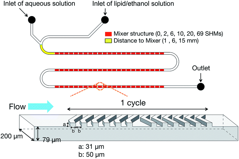 | ||
| Fig. 1 Schematic illustration of microfluidic device with 69 cycle numbers of staggered herringbone micromixers (SHM). The distance between the merging point of solutions and the first SHM were 1 mm, 6 mm, and 15 mm. We also made devices with 0, 2, 6, 10, and 20 SHM cycle numbers. | ||
At first, we investigated the SHM effect on the LNP size. In the literature, several research groups reported that high flow rate promotes the small-size LNP formation due to the rapid mixing when using the microfluidic device with micromixers. Micromixers have a suitable flow rate condition (a range of Re numbers) to provide high mixing efficiency; too high a flow rate reduces the mixing performance. In the case of the SHMs, the suitable range of Re was reported to be from 1 to 100. Thus, we also investigated the dependence of the LNP size on the flow rate ratio (FRR). Fig. 2(a) shows the relationship between the FRR and the LNPs size. The flow rate of the lipid solution was fixed at 0.1 mL min−1 and that of the aqueous solution was varied from 0.3 to 0.9 mL min−1. The LNP size decreased with increasing FRR regardless of the presence of the SHMs. Notably, the LNPs with a limiting diameter of 30 nm formed at the FRR of 9. LNPs in the size range of 20–30 nm, which are composed of one type of lipid, are considered to have the smallest size.9b In the case of the microfluidic device without the SHMs (blue), the LNP size was larger than that obtained for the microfluidic device with 69 SHM cycle numbers (red) for all FRR conditions. A large size difference of the LNPs was observed at the low FRR condition (Fig. 2(a)). For the production of LNP-based nanomedicine, the customized siRNA or chemotherapy drugs will be encapsulated into the LNPs and these materials will be contained in an aqueous solution.9b,c The consumption of these valuable and expensive chemicals must be reduced from a production cost perspective. Thus, the formation of small-size LNPs at the low FRR condition is desirable for LNP-based nanomedicine production. In addition, the high flow rate condition increases the pressure drop and requires high-pressure devices or equipment. Our result indicated that the microfluidic device with SHMs easily realized the formation of small-size LNPs and the FRR was also considered as essential to formation of small-size LNPs. We considered that the single unilamellar LNPs were formed in the microfluidic device. Typically, the LNPs sized smaller than 100 nm are considered as single unilamellar LNPs.12 The size of the LNPs was smaller than 100 nm and a reasonable size for single unilamellar LNPs. Fig. 2(b) and (c) show the distributions of LNP size formed in the microfluidic device with and without SHMs at the FRRs of 3 and 9, respectively. The mixer structure and the FRR affected the LNP size distribution. When we employed the microfluidic device with 69 SHM cycle numbers, the LNP size distribution was narrower compared to the distribution for the microfluidic device without the SHMs. However, the high FRR condition enabled the formation of LNPs with a narrow small-particle-size distribution without the SHMs, as shown in Fig. 2(c). A liposome formation mechanism has been proposed in several papers.13 The lipid molecules dissolved in ethanol solution are aggregated by self-assembly due to the increasing solution polarity. Then, intermediate structures called bilayered phospholipid fragments (BPFs) form and grow until the BPFs transform to closed vesicles. When the ethanol concentration is decreased rapidly to a critical ethanol concentration, BPFs cannot grow enough to form large-size LNPs. In contrast, the slow dilution rate of the ethanol concentration induces the formation of large-size LNPs.
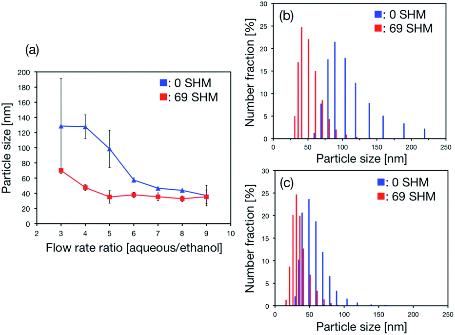 | ||
| Fig. 2 (a) Relationship between the flow rate ratio (FRR) and the produced LNP size. The error bars represent the standard deviation calculated from results obtained by repeating each LNP formation experiment three times. (b) and (c) Size distributions of LNPs formed in the microfluidic devices with and without SHMs at the FRRs of 3 and 9, respectively. The distance between the merging point of solutions and the first SHM was 1 mm. | ||
Hence, the SHM cycle numbers in the microchannel was changed to confirm the effect of mixing state on LNP size. We designed the microfluidic devices equipped with 0, 2, 6, 10, and 20 SHM cycle numbers and compared the LNP sizes formed by devices for each of these numbers. Fig. 3(a) shows the dependence of LNP size on FRR and the SHM cycle numbers. The LNP size decreased with increasing FRR regardless of the SHM cycle numbers. Size distributions of LNPs formed in the microfluidic devices with 2, 6, and 10 SHM cycle numbers at the FRRs of 3 and 9 are shown in Fig. 3(b) and (c), respectively. For the experimental data plotted in Fig. 2, we used the microfluidic device with 69 SHM cycle numbers from which we predicted that the decrease of the SHM cycle numbers caused the LNP size increase and the wide LNP size distribution. We considered that the mixing of aqueous and lipid solutions was essential to produce the narrow distribution of small-size LNPs by the microfluidic-based approach. The SHM cycle numbers partially affected the average size of the LNPs as shown in Fig. 3(a). Additionally, the size of the LNPs gradually shifted to larger LNP size by decreasing the SHM cycle numbers at the FRR of 3. On the other hand, the size distribution of the LNPs was almost the same at the FRR of 9, regardless of the SHM cycle numbers. Moreover, Fig. 2 and 3 suggested that the limiting SHM cycle numbers was 10 cycles to produce the small-size LNPs for all FRR conditions.
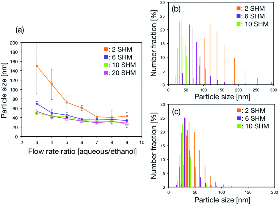 | ||
| Fig. 3 (a) Dependence of LNP size on FRR and the SHM cycle number. The error bars represent the standard deviation calculated from repeating each LNP formation experiment three times. (b) and (c) Size distributions of LNPs formed in the microfluidic devices with 2, 6, and 10 SHM cycle numbers at the FRRs of 3 and 9, respectively. The distance between the merging point of solutions and the first SHM was 1 mm. | ||
We carried out a preliminary experiment using a confocal laser scanning microscope to evaluate mixing of solutions. The microfluidic device with 10 SHM cycle numbers and the fluorescence-labeled lipid were used. The aqueous and lipid solutions could not be completely mixed for the mixer structure of 10 cycles under the high FRR condition (data not shown). From these results, we presumed that the formation of small-size LNPs with a narrow distribution required rapid dilution of the ethanol to a critical concentration rather than complete mixing of the solutions. For the microfluidic device without SHMs, we could not produce the small-size LNPs at the FRR of 3, because decreasing the ethanol concentration depends on the molecular diffusion. For 2 SHM cycle numbers, the ethanol concentration did not decrease quickly enough to form small-size LNPs at the end of the mixer structure in the microchannel. However, when we used the microfluidic devices with 10, 20, and 69 SHM cycle numbers, the ethanol concentration decreased immediately and small-size LNPs were formed unlike for 0 or 2 SHM cycle numbers. The LNP size formed by 6 cycles was slightly larger than the result of 10 cycles at FRR of 3. This suggested that the concentration of ethanol could not reach the critical concentration at the end of the mixer structure. The values of Re were calculated to be almost 50 and 130 for FRRs of 3 and 9, respectively. Generally, SHMs can work well in the Re range from 1 to 100.14 Thus, we considered that the difference between the aqueous and lipid solution volumes in the microchannel affected the formation behavior of LNPs at the FRR of 9. The flow rate at FRR of 9 was 1.0 mL min−1, and that included 0.9 mL of aqueous solution and 0.1 mL of lipid solution. Although the effect of the SHMs on the mixing efficiency was reduced compared to the low FRR condition, the concentration of ethanol could be decreased rapidly due to the dilution effect. The high volume fraction of aqueous phase that flowed into the microchannel made rapid dilution of the ethanol concentration possible.
Finally, we focused on the position of the SHMs in the microchannel. We examined whether the dilution rate of ethanol was the most significant factor for producing the small-size LNPs. Thus, microfluidic devices with three positions of the first SHM, at 1 mm, 6 mm, and 15 mm from the merging point of aqueous and ethanol solutions were used in order to confirm the effect of dilution rate on the LNP size. The cycle number of the SHMs was 10 for each device. We saw that the position of the first SHM affected the size distribution of LNPs. Fig. 4(a) and (b) show the size distributions of LNPs formed in the microfluidic device at the FRRs of 3 and 9, respectively. The LNP size increased with increasing the distance where the first SHM was located and the size distribution of LNPs showed a wide distribution at both FRR conditions. These results and molecular dynamics simulations supported the proposed mechanism that BPFs formed by aggregation of lipid molecules grew in the microchannel before the lipid solution reached the SHM. Molecular dynamics simulations have also been used for evaluating the transformation behavior of BPFs to closed LNPs.15 The transformation of BPFs depends on the free energy cost and line tension of the membrane. At the FRR of 3, the times necessary to reach the first SHM from the merging point of the solutions were calculated to be 2, 14, and 36 ms for 1, 6, and 15 mm positions, respectively. In addition, at the FRR of 9, the times necessary to reach SHM from the merging point of solutions was calculated to be 0.9, 6, and 14 ms for 1, 6, and 15 mm positions, respectively. At first, BPFs formed immediately at the interface of the aqueous and ethanol solutions. The concentration profile of ethanol at the interface of the solutions was narrowed due to the high flow velocity (40 mm s−1 to 105 mm s−1).9f,16 The concentration of ethanol was sufficient to allow growth of BPFs before reaching the SHM structure, because the ethanol concentration decrease depends on the molecular diffusion. However, the solutions containing BPFs and lipid molecules were mixed rapidly while passing through the SHM structure. Then, the concentration of ethanol was reduced to its critical concentration. When the concentration of ethanol reached its critical concentration, BPFs were transformed into closed LNPs, which are the thermodynamically favorable form. For these reasons, the size of the LNPs increased with the increasing distance where the first SHM was positioned and the wide distribution was seen. Moreover, the microfluidic device with 10 SHM cycle numbers (Fig. 4(a), 15 mm position) could produce smaller size LNPs than the microfluidic devices with 0 and 2 SHM cycle numbers (Fig. 2(b) and 3(b), 1 mm position) under the low FRR condition. When we used the microfluidic device with 10 SHM cycle numbers (15 mm), the rapid dilution of ethanol could be achieved while passing through the SHMs. In contrast, the microfluidic devices with 0 and 2 SHM cycle numbers were not effective for rapid dilution of ethanol, because the ethanol concentration decrease depends on the molecular diffusion. For this reason, the microfluidic devices with 0 and 2 SHM cycle numbers had only a limited effect on the dilution rate of ethanol concentration. Therefore, a long time was required to lower the ethanol concentration to the critical concentration compared with the microfluidic device having 10 SHM cycle numbers (15 mm position).
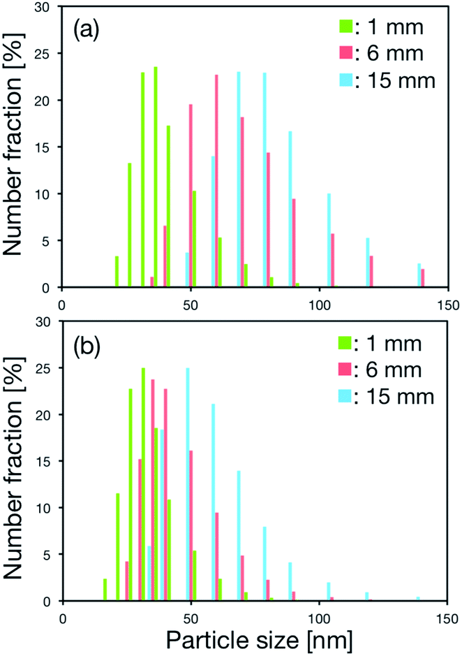 | ||
| Fig. 4 Distributions of LNP size formed in the microfluidic devices with different positions of the first SHM at the FRR of (a) 3 and (b) 9. The cycle number of the SHMs was 10. | ||
In conclusion, we have investigated the formation behavior of LNPs by using microfluidic devices equipped with different cycle numbers of SHMs. Precise controlling and tuning of LNP size was possible using the FRR and the SHM cycle numbers. In particular, the effect of SHMs on LNP size was observed for low to intermediate FRR conditions. We assumed that the rapid decrease of ethanol concentration to its critical concentration was essential to form small-size LNPs. The SHM cycle numbers and the position of the first SHM were also significant factors for producing the small-size LNPs. In our experimental system, 10 SHM cycle numbers led to the formation of the limited size LNPs with a narrow distribution. Consequently, we demonstrated that the microfluidic device with SHMs could easily produce monodispersed small-size LNPs without any complicated procedures. We expect the described strategy can become a fundamental process for production of LNP-based nanomedicines.
Acknowledgements
Part of this work was supported by the Hosokawa Powder Technology Foundation. MM acknowledges support from the Japan Society for the Promotion of Science (JSPS).Notes and references
- (a) T. Sun, Y. S. Zhang, B. Pang, D. C. Hyun, M. Yang and Y. Xia, Angew. Chem., Int. Ed., 2014, 53, 12320–12364 CAS; (b) H. Yin, R. L. Kanasty, A. A. Eltoukhy, A. J. Vegas, J. R. Dorkin and D. G. Anderson, Nat. Rev. Genet., 2014, 15, 541–555 CrossRef CAS PubMed; (c) Y. Malam, M. Loizidou and A. M. Seifalian, Trends Pharmacol. Sci., 2009, 30, 592–599 CrossRef CAS PubMed.
- (a) Q. Lin, J. Chen, Z. Zhang and G. Zheng, Nanomedicine, 2014, 9, 105–120 CrossRef CAS PubMed; (b) J. C. Kraft, J. P. Freeling, Z. Wang and R. J. Y. Ho, J. Pharm. Sci., 2014, 103, 29–52 CrossRef CAS PubMed; (c) N. T. Huynh, C. Passirani, P. Saulnier and J. P. Benoit, Int. J. Pharm., 2009, 379, 201–209 CrossRef CAS PubMed.
- (a) R. Duncan and M. J. Vicent, Adv. Drug Delivery Rev., 2013, 65, 60–70 CrossRef CAS PubMed; (b) H. Cabral, Y. Matsumoto, K. Mizuno, Q. Chen, M. Murakami, M. Kimura, Y. Terada, M. R. Kano, K. Miyazono, M. Uesaka, N. Nishiyama and K. Kataoka, Nat. Nanotechnol., 2011, 6, 815–823 CrossRef CAS PubMed.
- (a) S. Svenson, Eur. J. Pharm. Biopharm., 2009, 71, 445–462 CrossRef CAS PubMed; (b) S. H. Medina and M. E. H. EI-Sayed, Chem. Rev., 2009, 109, 3141–3157 CrossRef CAS PubMed.
- (a) R. T. Chacko, J. Ventura, J. Zhauang and S. Thayumanavan, Adv. Drug Delivery Rev., 2012, 64, 836–851 CrossRef CAS PubMed; (b) M. H. Smith and L. A. Lyon, Acc. Chem. Res., 2012, 45, 985–993 CrossRef CAS PubMed.
- (a) K. Kajimoto, Y. Sato, T. Nakamura, Y. Yamada and H. Harashima, J. Controlled Release, 2014, 190, 593–606 CrossRef CAS PubMed; (b) I. Khalil, K. Kogure, S. Futaki, S. Hama, M. Ueno, H. Kishida, M. Kucoh, Y. Mishima, K. Kataoka, M. Yamada and H. Harashima, Gene Ther., 2007, 14, 682–689 CrossRef CAS PubMed; (c) K. Kogure, R. Moriguchi, K. Sasaki, M. Ueno, S. Futaki and H. Harashima, J. Controlled Release, 2004, 98, 317–323 CrossRef CAS PubMed.
- (a) S. D. Perrault, C. Walkey, T. Jennings, H. C. Fisher and W. C. W. Chan, Nano Lett., 2009, 9, 1909–1915 CrossRef CAS PubMed; (b) F. Alexis, E. Pridgen, L. K. Molnar and O. C. Farokhazd, Mol. Pharm., 2008, 5, 505–515 CrossRef CAS PubMed.
- (a) M. J. Hope, M. B. Bally, G. Webb and P. R. Cullis, Biochim. Biophys. Acta, 1985, 812, 55–65 CrossRef CAS; (b) C. Huang, Biochemistry, 1969, 8, 344–352 CrossRef CAS.
- (a) R. R. Hood, D. L. DeVoe, J. Atencia, W. N. Vreeland and D. M. Omiatek, Lab Chip, 2014, 14, 2403–2409 RSC; (b) I. V. Zhigaltsev, N. Belliveau, I. Hafez, A. K. K. Leung, C. Hansen and P. R. Cullis, Langmuir, 2012, 28, 3633–3640 CrossRef CAS PubMed; (c) D. Chen, K. T. Love, Y. Chen, A. A. Eltoukhy, C. Kastrup, G. Sahay, A. Jeon, Y. Dong, K. A. Whitehead and D. G. Anderson, J. Am. Chem. Soc., 2012, 134, 6948–6951 CrossRef CAS PubMed; (d) K. Kitazoe, Y. S. Park, N. Kaji, Y. Okamoto, M. Tokeshi, K. Kogure, H. Harashima and Y. Baba, PLoS One, 2012, 7, e39057 CAS; (e) K. Kitazoe, J. Wang, N. Kaji, Y. Okamoto, M. Tokeshi, K. Kogure, H. Harashima and Y. Baba, Lab Chip, 2011, 11, 3256–3262 RSC; (f) A. Jahn, S. M. Stavis, J. S. Hong, W. N. Vreeland, D. L. DeVoe and M. Gaitan, ACS Nano, 2010, 4, 2077–2087 CrossRef CAS PubMed.
- S. Batzri and E. D. Korn, Biochim. Biophys. Acta, 1973, 298, 1015–1019 CrossRef CAS.
- J. C. McDonald and G. M. Whitesides, Acc. Chem. Res., 2002, 35, 491–499 CrossRef CAS PubMed.
- F. Szoka Jr, Annu. Rev. Biophys. Bioeng., 1980, 9, 467–508 CrossRef CAS PubMed.
- (a) M. Antonietti and S. Forster, Adv. Mater., 2003, 15, 1323–1333 CrossRef CAS PubMed; (b) D. D. Lasic, Biochem. J., 1988, 256, 1–11 CAS.
- (a) N. T. Nguyen and Z. Wu, J. Micromech. Microeng., 2005, 15, R1–R16 CrossRef; (b) A. D. Stroock, S. K. W. Dertinger, A. Ajdari, I. Mezic, H. A. Stone and G. M. Whitesides, Science, 2002, 295, 647–651 CrossRef CAS PubMed.
- (a) T. Nakamura and W. Shinoda, J. Chem. Phys., 2013, 138, 124903 CrossRef PubMed; (b) W. Shinoda, T. Nakamura and S. O. Nielsen, Soft Matter, 2011, 7, 9012–9020 RSC.
- D. E. Hertzog, X. Michalet, M. Jager, X. Kong, J. G. Santiago, S. Weiss and O. Bakajin, Anal. Chem., 2004, 76, 7169–7178 CrossRef CAS PubMed.
Footnote |
| † These authors contributed equally to this work. |
| This journal is © The Royal Society of Chemistry 2015 |