Shiwei Wang*,
Zhenwei Wang,
Na Zhao,
Jing Jiang and
Qian Li*
National Center For International Joint Research of Micro-Nano Molding Technology, Zhengzhou University, 450001, Zhengzhou, Henan, China. E-mail: shiweiwang@zzu.edu.cn; qianli@zzu.edu.cn; Fax: +86-0317-67781750; Tel: +86-0317-67781750
First published on 1st May 2015
A novel stripe morphology was investigated in a micro-injection molded isotactic polypropylene gear. The annealing treatment was performed on the gear tooth under different temperature and time to control its morphology evolution. This work provides a new way to explore the morphology evolution of micro injection molded products.
A commercial grade iPP, F401, with a melt flow rate of 2.3 g/10 min (ASTM D1238, 230 °C, and 2.16 kg load) supplied by Lanzhou Petroleum Chemical Co, Ltd. (PR China) was used in this work. The test sample is a iPP gear, with a thickness of 450 μm, a gear teeth length of 1000 μm, half gear teeth width of 350 μm, as shown in Fig. 1. It was manufactured by MIM machine (Babyplast 6/10P) at 4 MPa and 200 °C. For annealing experiments, The iPP gears were placed in an oven at temperature ranged from 60 to 160 °C for different time (20, 40, 60, 80, 120 min). A polarized light microscopy (Olympus, BX51) was used to characterize morphology of the gear samples. The wide angle X-ray diffraction (WAXD) was performed on a Bruker NanoStar system. Monochromatized Cukα (λ = 1.54 Å) radiation was used for all experiments. The scanning position was the surface of central part of the gear tooth as shown in Fig. 1(a). The generator settings were at 45 kV and 0.67 mA. The crystallinity of the samples were calculated according to Liu et al.8 The surface images of the etched samples were obtained using a scanning electron microscope (JEOL, JSM-7500F).
Fig. 1(a) shows the polarized morphology of the central part of MIM iPP gear tooth without annealing. The morphology was taken directly from the gear sample placed on the stage using transmission mode. Clear stripes morphology displays on the Fig. 1(a) from central to the both sides, from surface to central, the width of the strip increased, while the brightness of the strip decreased. This novel stripe morphology has not been reported yet. In order to probe the structure in full, surface morphology was investigated besides only measuring the thick samples with PLM. The surface morphology of the etched gear tooth was detected by SEM and a clear oriented texture appeared as shown in Fig. 1(b).
The annealing treatments were performed on the gear tooth under different temperature and different time. Fig. 2(a) shows gear teeth annealed at 60 °C for 20 minutes. Compared with Fig. 1, the width of stripes in Fig. 2(a) increases, also the shape of the stripes shows some disparity. This phenomenon presents more obvious for the gear teeth annealed at 120 °C for 20 minutes as shown in Fig. 2(b). The number of strips increases significantly, especially in the central of the teeth and results in reducing of the dark stripe. With the increase of the annealing temperature, the width of the fuzzy layer increases, as shown in Fig. 2(c). When the annealing temperature rise to 160 °C, the dark strip becomes even narrow and the width of the fuzzy edges enlarges obviously. Extension of the annealing time shows little affection on the morphology of the teeth, as shown in Fig. 2(d), the same temperature while 100 min longer compared with the sample of Fig. 2(c).
![]() | ||
Fig. 2 MIM iPP gear tooth annealing for (a) 20 min at 60 °C, (b) 20 min at 120 °C, (c) 20 min at 160 °C and (d) 120 min at 160 °C. |
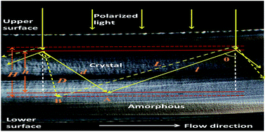
The result shows a brief multi-layer morphology from central to the surface of the MIM sample in Fig. 3(a). The slice with thickness of about 13 μm was taken along a plane parallel to the flow direction from the mid-width region of the gear. The ‘‘skin–core’’ structure of MIM sample is similar to the conventional molding one except for the thickness of oriented shear layer and core layer.9 The moving ability of the molecular chain was increased by the annealing treatment greatly, which made the gradient difference molecular chains interact with each other.10 For a macroscopic view, the width of the dark strip in the center of the teeth decreases. It is well known that iPP is a semi-crystalline material, which contains crystalline and amorphous parts.11 The molecular chains stack into regular lamellar which makes the refraction index anisotropy in the crystalline region, while the refraction index in the amorphous region shows isotropy. The formation mechanism of stripe morphology and its evolution is shown in Fig. 3(b). The region between upper and lower solid line in Fig. 3(b) is marked as crystalline region, which has a depth of h. When the polarized light incidents on the upper surface of the crystalline region, the birefringence appears. So when the two lights intersect on the surface of crystalline region, the interference appears. The equation Δ = l − d is used to get the optical path difference, where l stands for the longer distance optical path and d stands for the shorter distance optical path. If Δ is equal to an odd times or an integer multiple of a half wavelength, the cross point of the two lights show dark stripe or light stripe, respectively. Therefore, the novel morphology is attributes to the optical path difference of the polarized light when it incents to the crystalline region. While for the morphology evolution, the change of the crystalline structure plays an important part. The crystalline structure of polymer becomes regular and perfect after annealing,6,7 which in turn improve the refraction index. Similarly, the region between upper and lower dotted line in Fig. 3(b) is marked as the annealed crystalline region with a depth H. Due to the change of width in the crystalline region, the optical path of the incent polarized light changes from d to D, which improves the Δ and changes the optical path difference, and finally results in the increase of stripe number and decrease of the strip width. The crystalline structure variation of the MIM samples were proved by WAXD results in Fig. 4. There are only two peaks locates at 2 theta of 15° and 21° for the sample annealed at 60 °C as shown in Fig. 4(a). With rise of the annealing temperature, two additional peaks appear for the sample annealed at higher temperature and the intensity of the additional peaks rises as shown in Fig. 4(a), as well as the improves of crystallinity in Fig. 4(b). This fact is due to the better crystalline structure induced by the secondary crystallization after annealing, and the optical path difference becomes large and the spacing between stripes becomes narrower when polarized light pass though the changed crystalline region.
![]() | ||
Fig. 3 Multi-layer morphology of MIM gear annealed at 120 °C for 20 min (a), and schematic diagram of the strip formation (b). |
![]() | ||
Fig. 4 WAXD patterns (a) and crystallinity (b) of MIM iPP gear tooth annealed at different temperature for 20 min. |
This journal is © The Royal Society of Chemistry 2015 |