
Microencapsulation of bacterial strains in graphene oxide nano-sheets using vortex fluidics†
M. Haniff Wahidab,
Ela Erogluc,
Sian M. LaVarsa,
Kelly Newtona,
Christopher T. Gibsona,
Uwe H. Stroeherd,
Xianjue Chena,
Ramiz A. Boulosa,
Colin L. Raston*a and
Sarah-L. Harmer*a
aCentre for NanoScale Science and Technology, School of Chemical and Physical Sciences, Flinders University, Bedford Park, SA 5042, Australia. E-mail: colin.raston@flinders.edu.au; sarah.harmer@flinders.edu.au
bDepartment of Chemistry, Faculty of Science, Universiti Putra Malaysia, 43400 Serdang, Selangor, Malaysia
cARC Centre of Excellence in Plant Energy Biology, The University of Western Australia, 35 Stirling Highway, Crawley, WA 6009, Australia
dSchool of Biological Sciences, Flinders University, Bedford Park, SA 5042, Australia
First published on 14th April 2015
Abstract
Wrapping bacterial cells with graphene oxide sheets using a vortex fluidic device (VFD) effectively limits cellular growth for a certain time period whilst sustaining biological activity. This simple and benign method in preparing such a composite material relies on the shear within the film in the device without compromising the cellular viability. In principle, the process is scalable for large volumes, for operating the VFD(s) under continuous flow mode. Moreover, acquiring SEM images was possible without pre-coating the composite material with a metallic film, with limited charging effects. This establishes the potential for interfacing material with graphene oxide, which could be extended to more conductive graphene layers, as an effective approach for simplifying characterization using SEM.
Introduction
Microorganisms such as bacteria have attracted considerable interest for their use in commercial applications. Being abundant in nature, they also exhibit many different morphologies and metabolic pathways, some of which are unique to bacteria.1 Accordingly microorganisms have potential in prospective sustainable technologies for the future. Thus far bacteria have been used in a wide range of sustainable applications, ranging from food manufacturing, the production of antibiotics, drugs, enzymes, biofuels and solvents1,2 to biomining3,4 and bioremediation.5,6 Additionally, with the emerging advances in nanotechnology, innovative approaches such as the integration of nanomaterials and microorganisms provide access to novel functional materials. Some of these studies focus on interfacing nanomaterials with biological cells to detect biocomponents or to investigate biological phenomena,7 in particular bioremediation,8–10 the synthesis of bio-templated materials for various novel applications such as supercapacitors,11 surface enhanced Raman scattering (SERS) substrates,12 and lithium storage,13 or for immobilization purposes.14–16Despite the number of promising applications of bacteria, their direct usage is challenging because bacterial activity depends critically on several environmental factors. For instance, the delivery of probiotics bacteria to the gastrointestinal tract is usually hindered due to the adverse pH conditions of the tract.17 Various techniques have been implemented in order to increase the applicability of bacteria through cellular protection. This includes microencapsulation17–22 which is effective in providing cells with a protective layer, which can enhance their viability during processing, and facilitate their delivery to targeted sites such as in the case of probiotics bacteria.17–19 In addition, such encapsulated cells have featured in bioremediation20,21 and targeted agricultural deliveries where extended shelf-life and controlled microbial release were achieved.22 Given that the majority of encapsulated bacteria are used in the food industry, common materials used for the encapsulation are food grade polymers such as calcium-alginate gel, kappa-carrageenan, gellan gum, gelatin and starch.17,23 Nevertheless, due to the growing potential applications of bacteria in diverse fields, there is a need to seek alternative coating materials with the scope of protecting the cells as well as imparting additional functionality to them. Several examples have recently been reported, including introducing superparamagnetic nanoparticles for magnetic field responses,24,25 silica to enhance thermal durability,26 and graphene to impart electrical conductivity.27,28 Another potential encapsulating material for microorganisms is graphene oxide (GO) which has a number of advantageous properties such as biodegradability,29 flexibility,30 robustness,30 transparency30 and amphiphilicity.31 We recently reported on the encapsulation of microalgae, Chlorella vulgaris with GO layers while maintaining biological activity of the cells.16 The encapsulation was proven to reduce the rate of cell division for a certain time interval and thus established the potential of the approach for immobilization purposes in general. Furthermore, a recent study showed that GO can act as a scaffold for bacterial attachment, proliferation and biofilm formation for Escherichia coli.32
Although substantial efforts have been made to interface biological cells with various functional nanomaterials, the preparation techniques are limited and require further development.23 A facile, efficient and environmentally friendly technique is a prerequisite in developing industrial applications.23 Herein we develop the use of a vortex fluidic device (VFD) to effectively interface graphene oxide (GO) sheets to the surface of two different strains of bacterial cells, Staphylococcus aureus and Rhodococcus opacus, in order to impart novel function to the cells in the hybrid materials. Related to this work is the use of the VFD to prepare functional multi-layer graphene–algae and graphene oxide (GO)–algae hybrid materials.10,16 In the VFD, a rapidly rotating tube generates a thin microfluidic film with rapid micro-mixing of reagents therein, and the mechanoenergy in the film is effective in increasing reaction rates, and therefore reducing the processing times.33 Importantly, the VFD can be operated in the confined mode and also continuous flow mode, and it has a diversity of processing capabilities, including in organic synthesis,33–37 controlled growth of the polymorphs of calcium carbonate,38 formation of mesoporous silica at room temperature with control over the pore size,39 compacting single walled carbon nanotube into toroidal structures,40 exfoliation of graphene and boron nitride,41 controlled decoration of nanoparticles on 2D nanomaterials,42–44 preparation of functional hybrid bio-nanomaterials,10,16,45 and the refolding of proteins.46
Selection of the bacterial strains for this study was based on the disparate physical structures of spherical S. aureus and rod shaped R. opacus cells. Exploring different cellular morphologies can be useful to understand the effects of shearing forces generated within the microfluidic film in the VFD, towards the bacteria, and subsequently towards the GO in inducing the wrapping process. While S. aureus is easy to grow and could represent a model to study the VFD wrapping efficiency and the effects of shear on bacteria, R. opacus has the advantage of being able to degrade pollutants.47 Since wrapping with GO also has the advantage of water treatment,48 its hybrid with bacterial cells like R. opacus is attractive in developing more efficient waste treatment systems.
Experimental
In a typical experiment, bacterial cultures were first prepared in a nutrient media solution1 until the cells reached their stationary phase prior to use in these experiments (Fig. 1 and ESI S1.1†). GO used in this study was prepared following the modified Hummer's method (ESI-S1.2†).49,50 For the cell viability assay of the bacteria (without GO addition) processed in the VFD, bacteria were initially processed at different rotational speeds ranging from 2000 to 8000 rpm for one minute per sample, using a VFD housing a 10 mm OD diameter borosilicate NMR tube, inclined at 45 degrees. Processed cells were then stained with the fluorescent dyes, SYBR Green I, for live cells staining, and propidium iodide (PI) for dead cells staining. Accordingly, untreated and heat ‘killed’ bacteria were prepared as controls for VFD processed bacteria. Viability of all samples was analysed using flow cytometry (ESI-S2†). GO wrapping of the bacteria was carried out in the VFD tube at 5000 and 8000 rpm for 1 minute after mixing 0.5 mL of GO solution (0.1 mg mL−1) with 0.5 mL of bacterial solution in the stationary phase of their growth. The mixture was then transferred into nutrient media solution and bacterial growth was monitored using optical density (ESI-S3†).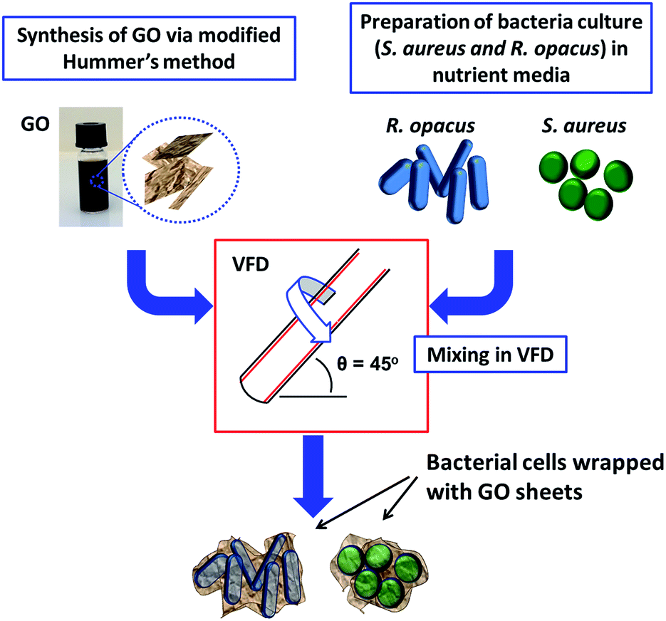 | ||
| Fig. 1 Schematic illustration of the preparation of GO wrapped bacteria using a vortex fluidic device (VFD) housing a 10 mm diameter borosilicate glass NMR tube operating in the confined mode.33 | ||
Results and discussion
Flow cytometry analysis data in Fig. 2 shows that S. aureus and R. opacus exhibit slightly different cytometric characteristics, potentially due to the different cell morphologies and surface structures present on the bacteria.51 Initial experiments demonstrate the efficacy of SYBR and PI for distinguishing between live and dead bacterial cells which was useful for understanding the effect of VFD processing towards the viability of the bacteria (Fig. 2). Regardless of the different processing speeds, flow cytometric analysis of the VFD processed samples showed similar cytometric characteristics for all speeds, ranging from 2000 rpm to 8000 rpm, which was also similar to those exhibited by untreated cells, where a high density of live cells was observed. This suggests that there was only a minimal effect on the cells from their processing in the VFD (ESI-S4†). Fig. 2 shows the results for S. aureus and R. opacus processed at two different speeds (5000 and 8000 rpm) as a representation of the VFD processed samples. After confirming the viability of the cells, these two speeds, i.e. 5000 and 8000 rpm, were selected for wrapping the bacteria with GO sheets using the VFD. Of note is that the same speeds were also used in our previous study for the preparation of multi-layer graphene–algae hybrid material.10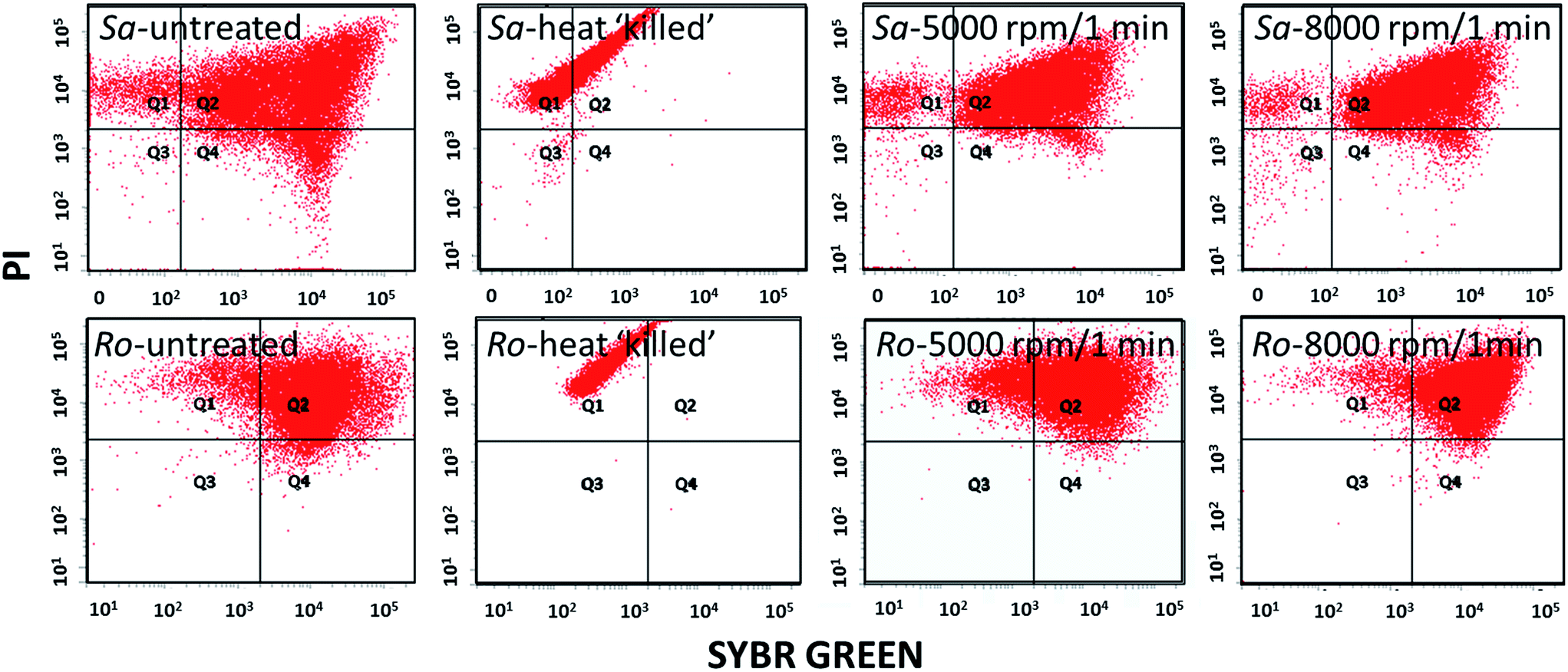 | ||
| Fig. 2 Flow cytometry analysis of S. aureus (top row) and R. opacus (bottom row). Sa and Ro-untreated and heat ‘killed’ represents control samples and Sa and Ro-5000 & 8000 rpm/1 min shows cytogram of bacteria after processing in the VFD at 5000 and 8000 rpm for 1 minute respectively. | ||
Scanning electron microscopy (SEM) images of only bacterial cells, and GO wrapped bacterial cells were recorded and are compared in Fig. 3. Preliminary results showed that bacteria interfaced with GO can be imaged under SEM without pre-coating with a metallic film, although there are small charging effects (Fig. 3(a)). However for untreated bacterial cells not coated with either a metallic film or GO, charging effects were prevalent, distorting the images (Fig. 3(b)). Hence, it can be anticipated that by interfacing the cells with more conductive graphene sheets such as reduced graphene oxide or pure graphene, clear SEM images can be acquired. Nevertheless, in order to minimize the charging effects due to the less electron conductive property of GO, all samples were pre-coated with 5 nm platinum prior to SEM imaging. As shown in Fig. 3(c) and (d), untreated bacteria samples have smooth surfaces and there were pronounced charging effects. In contrast, the bacteria interfaced with GO clearly have the bacteria wrapped with GO sheets.
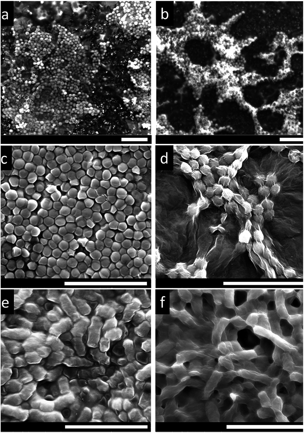 | ||
| Fig. 3 SEM images of bacteria (a) S. aureus interfaced with GO sheets, and (b) S. aureus only. Both (a) and (b) were imaged without pre-coating with a platinum metal film. (c) S. aureus only (d) GO wrapped S. aureus (e) R. opacus only, and (f) GO wrapped R. opacus. (c–f) samples were pre-coated with platinum prior to SEM imaging (scale bars: 5 μm). | ||
The SEM results are supported by transmission electron microscopy (TEM), atomic force microscopy (AFM) and Raman spectroscopy. TEM images of the GO wrapped bacteria exhibit wrinkles at the interface of the bacteria, revealing wrapping features of the GO on the surface of the bacteria, which was not observed in untreated bacteria samples (Fig. 4). Furthermore, selected area electron diffraction pattern of the graphene wrapped bacteria shows typical electron diffraction for GO layers, as shown in the inset of Fig. 4(d). AFM analysis under tapping mode revealed different surface topography for bacterial cells with and without GO (Fig. 5). For bacterial cells without GO, smooth surfaces were observed whereas features of wrinkles are demonstrated for GO encapsulated cells, which is characteristic of GO sheets. The difference in surface properties can also be seen in the phase images of AFM shown in the inset images in Fig. 5.
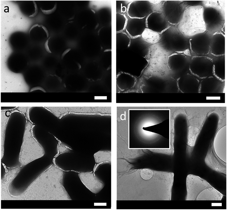 | ||
| Fig. 4 TEM images of (a) S. aureus only, (b) S. aureus wrapped with GO, (c) R. opacus only, and (d) R. opacus wrapped with GO and the selected area electron diffraction pattern in the inset (scale bars: 500 nm). | ||
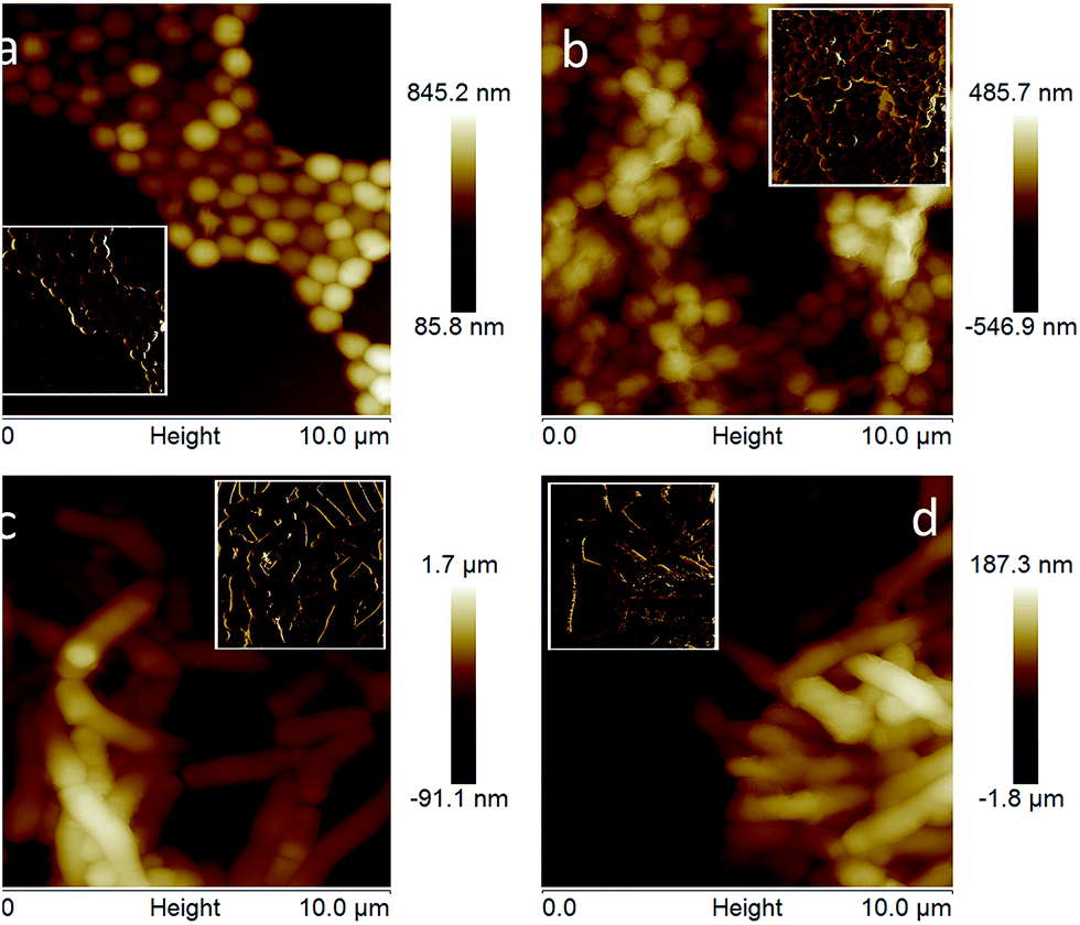 | ||
| Fig. 5 AFM images of bacteria (a) S. aureus only, (b) GO wrapped S. aureus, (c) R. opacus only, and (d) GO wrapped R. opacus. Inset images display phase images of the same samples. | ||
Raman spectra and images of GO wrapped bacteria are shown in Fig. 6, with Fig. 6(b) and (c) showing ×100 optical microscope images of GO wrapped S. aureus deposited on a cleaned silicon surface. The surface coverage of the S. aureus is quite high and given their small size (approximately 1 μm or less) it is difficult to discern individual bacteria. AFM images were acquired in approximately the same region as these optical micrographs and show the typical shape and structure of the S. aureus bacteria (Fig. 6(a)). Fig. 6(d) is a Raman image plotting the intensity of the 1600 cm−1 peak typical for the graphitic band of GO. Clearly from the bright regions on Fig. 6(c), the GO is covering the S. aureus bacterial surface. Fig. 6(i) is a Raman single spectra acquired on the image and shows the distinctive peaks of the D and G bands, at 1350 and 1600 cm−1 respectively, for GO, being consistent with previously reported values.50 The peaks at 520 and 965 cm−1 are also shown, which are from the underlying silicon substrate. Fig. 6(e)–(h) and (j) show optical images, Raman images and a Raman spectrum for the R. opacus bacteria covered in GO. Fig. 6(e) is an optical image and due to the much larger size of the rod-shaped R. opacus (1 μm wide and ∼4–5 μm long) they are easily discernible using the ×100 objective on the Raman microscope. Fig. 6(f) shows the same region as the image in Fig. 6(e) as a Raman image generated from the GO graphitic band at 1600 cm−1. The bright regions again indicate the presence of GO on the bacteria, which coincide with the position of the bacteria. Fig. 6(g) and (h) are zoomed in optical and Raman images of a particular bacterium, highlighted in Fig. 6(e) and (f). The data in Fig. 6(g) and (h) further demonstrate the covering of the bacteria with GO. The Raman image in Fig. 6(h) is, once again, corresponds to the GO graphitic band at 1600 cm−1. Fig. 6(j) shows a typical spectrum from the image and shows the distinctive peaks D and G bands at 1350 and 1600 cm−1 respectively for GO.52
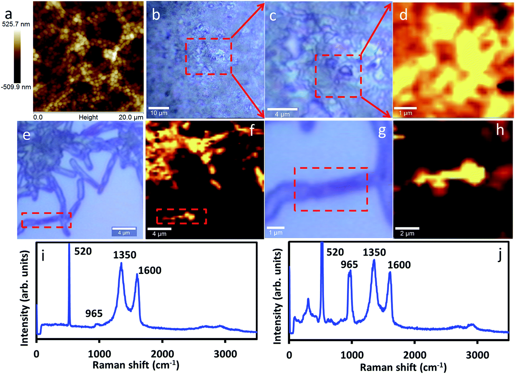 | ||
| Fig. 6 (a) AFM image acquired in approximately the same region as the optical micrographs of the S. aureus bacteria. (b) Optical microscope image (×100) of GO wrapped S. aureus deposited on a cleaned silicon surface and (c) zoomed in image of (b). (d) Raman image, plotting the intensity of the 1600 cm−1 peak typical for the graphitic band of GO. (e) Optical microscope image of GO wrapped R. opacus, (f) Raman image of (e), (g and h) zoomed in image of (e and f) respectively. (i and j) Raman single spectra acquired on samples d and h respectively. | ||
The growth of GO wrapped bacteria was monitored using optical density (OD) measurements (ESI-S7†). The validity of using OD measurements for bacterial growth was also verified by its calibration with viable cell counting (ESI-S8†). According to these calibration curves, 1.0 OD unit (at 600 nm) is found to be equivalent to approximately 7 × 10⁸ CFU mL−1 (colony forming units) S. aureus cells, and 4 × 10⁷ CFU mL−1 R. opacus cells. For a better understanding on the differences between the growth of untreated bacteria and GO-wrapped bacterial cells, kinetic models were applied. Due to the more pronounced lag phase within the GO wrapped cells, a logistic growth model was applied for modelling the overall bacterial growth, including all three phases (i.e. lag, exponential, stationary). The amount of X bacterial concentration at time t is given according to the following equation, where X0 is the initial and Xm is the maximum cell concentration at, and kc is the apparent growth rate (see ESI-S9† for the detailed derivation stages of the following equation):53
 | (1) |
Calculation of the logistic constants (a, b, and c), curve fitting, and the statistical analysis in the form of R2 (coefficient of determination, as a parameter to show how well a statistical model fits the experimental observations) were carried out by a software program CurveExpert 1.4, and given in Fig. 7 and 8 below. In addition to the logistic model, specific growth rate of the exponential phase (μexp) were also found by calculating the slope of the linear data range of the exponential growth phase. Apparent growth rate (kc) of the overall experiment and specific growth rate of the exponential phase (μexp) are given in Table 1.
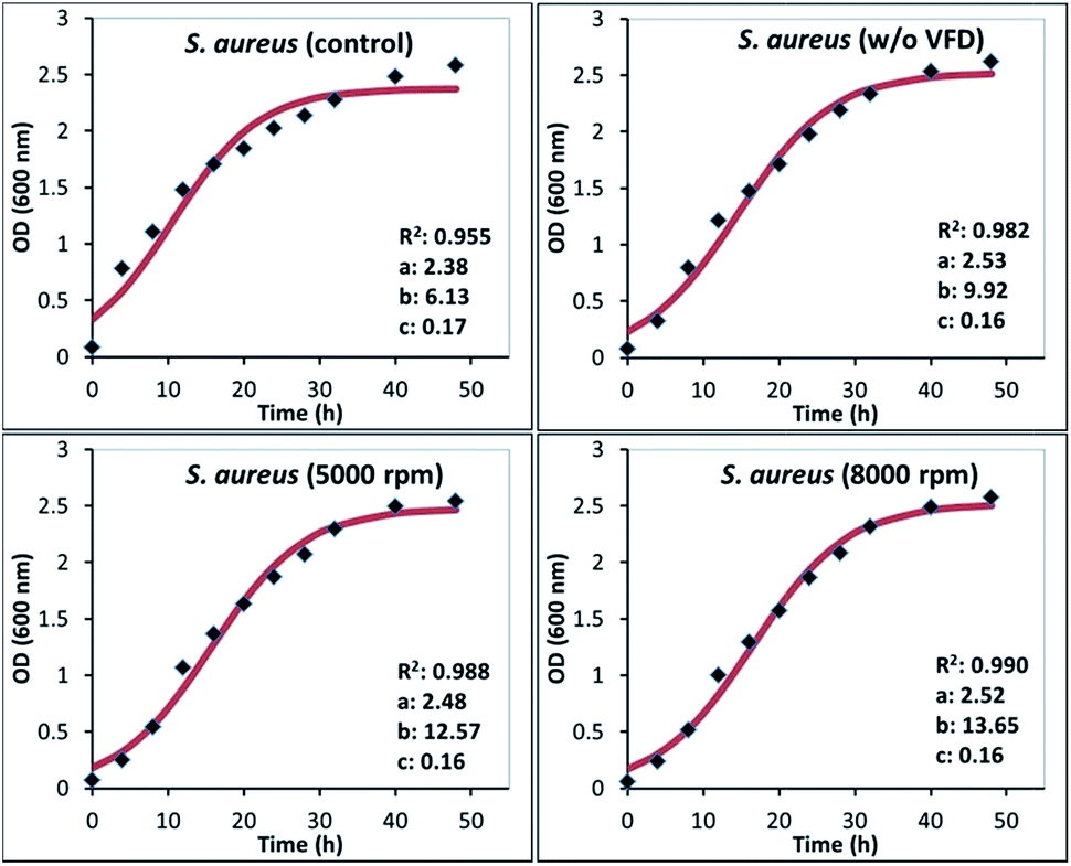 | ||
| Fig. 7 Bacterial growth curves for S. aureus cells regrown in nutrient media after wrapping with GO. Inset information of each figure shows the logistic model constants of eqn (1) (a, b, and c), and the coefficient of determination (R2). | ||
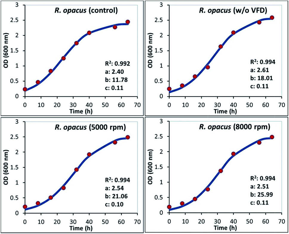 | ||
| Fig. 8 Bacterial growth curves for R. opacus cells regrown in nutrient media after wrapping with GO. Inset information of each figure shows the logistic model constants of eqn (1) (a, b, and c), and the coefficient of determination (R2). | ||
| Samples | kc (h−1) | μexp (h−1) |
|---|---|---|
| S. aureus (control) | 0.173 | 0.038 |
| S. aureus (5000) | 0.162 | 0.060 |
| S. aureus (8000) | 0.159 | 0.063 |
| S. aureus (w/o VFD) | 0.159 | 0.071 |
| R. opacus (control) | 0.108 | 0.047 |
| R. opacus (5000) | 0.102 | 0.055 |
| R. opacus (8000) | 0.108 | 0.061 |
| R. opacus (w/o VFD) | 0.105 | 0.056 |
Detailed growth analysis revealed that GO wrapped bacteria retained their biological activity even after interfacing with graphene oxide (Fig. 7 and 8). While all cases showed a successful fit for logistic growth model, GO wrapped cells displayed relatively better fitting compared to their untreated bacteria controls, particularly for S. aureus. This might be caused by the more pronounced lag phase for the GO wrapped bacterial cells, due to the physical boundaries caused by the surrounding GO nano sheets for a certain time interval, which was ∼8 hours for GO wrapped S. aureus and ∼16 hours for GO wrapped R. opacus, with both processed in VFD. The main difference between the VFD processed and unprocessed GO-wrapped bacterial samples (w/o VFD) was that the lag time was longer for the samples processed in the VFD, allowing the cells a longer microencapsulation stage, whereas without VFD processing, samples escaped from their matrix faster (∼4 hours for S. aureus, and ∼8 hours for R. opacus). According to the growth rates given in Table 1, GO wrapped S. aureus cells had slightly lower apparent growth rates (kc), while kc values were quite similar for R. opacus cells compare to their unwrapped cell counterparts. On the other hand, both S. aureus and R. opacus cells showed distinctively higher growth rates during their exponential phase once being released from their entrapment matrix, while maintaining their biological activity. A similar result was also observed in our previous studies with GO wrapped Chlorella vulgaris microalgal cultures.16 The decrease in the cellular growth rate of the bacteria due to GO microencapsulation is an controllable immobilization strategy for processing industrially relevant bacteria while maintaining their biological activity.14
Conclusions
Facile wrapping of bacteria with GO using vortex fluidics has been successfully achieved while keeping the cells alive and biologically active. The wrapped cells had a longer lag time of growth due to their restricted environment within the GO sheets after processing in the VFD. In order to achieve higher microencapsulation efficiencies, keeping the GO-wrapped cells within their growth environment for extended periods may be an issue, in facilitating cell growth and escape from the GO matrix.VFD processing is effective for wrapping or interfacing microorganisms with GO as a thin layered material. We note that other methods to interface graphene sheets onto the surface of microorganisms usually involves extensive chemical modification of the graphene sheets, such as functionalization with protein as reported by Mohanty et al.28 Similarly Kempaiah et al. established that calcium-ion functionalized graphene sheets can easily interface with yeast cells whereas unfunctionalized graphene sheets fail to interface with the cells.27 Herein, we demonstrate the encapsulation of cells without the need for chemical modification of the graphene sheets. The process has potential for surface functionalization of bacterial cells, immobilizing them for applications in devices, sensors, controlled drug release and targeted delivery, wastewater treatment, for example. While other thin layered materials can also be considered for making composite materials involving VFD wrapping, including hexagonal boron nitride, and molybdenum and tungsten disulphides (MoS2 and WS2 respectively). Also noteworthy, is that interfacing soft material with GO or more conductive graphene sheets can provide a conductive layer around the material, without the need for pre-coating for SEM studies, for example with platinum. This offers scope as a general technique for SEM imaging, noting the VFD itself is a rather inexpensive technology.33
Acknowledgements
We gratefully acknowledge support of this work by the Australian Research Council, the Government of South Australia and the National Health and Medical Research Council. M.H. Wahid would like to thank the Malaysian Government and Universiti Putra Malaysia for his PhD research funding. TEM, SEM and AFM studies were carried out using facilities in Adelaide Microscopy at The University of Adelaide and Flinders University, supported by the Australian Microscopy and Microanalysis Research Facility (AMMRF).Notes and references
- K. Todar, Todar's online textbook of bacteriology, 2006 Search PubMed.
- E. Rosenberg, The Prokaryotes, 2006, pp. 284–298 Search PubMed.
- C. L. Brierly, Hydrometallurgy, 2001, 59, 249–255 CrossRef.
- L. Valenzuela, A. Chi, S. Beard, A. Orell, N. Guiliani, J. Shabanowitz, D. F. Hunt and C. A. Jerez, Biotechnol. Adv., 2006, 24, 197–211 CrossRef CAS PubMed.
- K. S. M. Rahman, T. J. Rahman, Y. Kourkotas, I. Petsas, R. Marchant and I. M. Banat, Bioresour. Technol., 2003, 90, 159–168 CrossRef CAS PubMed.
- R. Singh, P. Debarati and R. K. Jain, Trends Microbiol., 2006, 14, 389–397 CrossRef CAS PubMed.
- P. Nguyen and V. Berry, J. Phys. Chem. Lett., 2012, 3, 1024–1029 CrossRef CAS PubMed.
- J. Raff, U. Soltmann, S. Matys, S. S-Pobell, H. Bottcher and W. Pompe, Chem. Mater., 2003, 15, 240–244 CrossRef CAS.
- M. Perullini, M. Jobbagy, N. Mouso, F. Forchiassin and S. A. Bilmes, J. Mater. Chem., 2010, 20, 6479–6483 RSC.
- M. H. Wahid, E. Eroglu, X. Chen, S. M. Smith and C. L. Raston, Green Chem., 2013, 15, 650–655 RSC.
- H. Sun, L. Cao and L. Lu, Energy Environ. Sci., 2012, 5, 6206–6213 CAS.
- D.-P. Yang, S. Chen, P. Huang, X. Wang, W. Jiang, O. Pandoli and D. Cui, Green Chem., 2010, 12, 2038–2042 RSC.
- H.-W. Shim, Y.-H. Jin, S.-D. Seo, S.-H. Lee and D.-W. Kim, ACS Nano, 2011, 5, 443–449 CrossRef CAS PubMed.
- Y. Liu, M. H. Rafailovich, R. Malal, D. Cohn and D. Chidambaram, Proc. Natl. Acad. Sci. U. S. A., 2009, 106, 14201–14206 CrossRef CAS PubMed.
- H. K. Baca, E. Carnes, S. Singh, C. Ashley, D. Lopez and C. J. Brinker, Acc. Chem. Res., 2007, 40, 836–845 CrossRef CAS PubMed.
- M. H. Wahid, E. Eroglu, X. Chen, S. M. Smith and C. L. Raston, RSC Adv., 2013, 3, 8180–8183 RSC.
- A. K. Anal and H. Singh, Trends Food Sci. Technol., 2007, 18, 240–251 CrossRef CAS.
- M. A. Islam, C.-H. Yun, Y.-J. Choi and C.-S. Cho, J. Microbiol. Biotechnol., 2010, 20, 1367–1377 CrossRef CAS PubMed.
- M. T. Cook, G. Tzortzis, V. V. Khutoryanskiy and D. Charalampopoulos, J. Mater. Chem. B, 2013, 1, 52 RSC.
- S. S. Bang and M. Pazirandeh, J. Microencapsulation, 1999, 16, 489–499 CrossRef CAS PubMed.
- H.-W. Tong, B. R. Mutlu, L. P. Wackett and A. Aksan, Biotechnol. Bioeng., 2014, 111, 1483–1493 CrossRef CAS PubMed.
- R. P. John, R. D. Tyagi, S. K. Brar, R. Y. Surampalli and D. Prevost, Crit. Rev. Biotechnol., 2011, 31, 211–226 CrossRef CAS PubMed.
- K. Kailasapathy, Curr. Issues Intest. Microbiol., 2002, 3, 39–48 CAS.
- R. F. Fakhrullin, J. G-Alonso and V. N. Paunov, Soft Matter, 2010, 6, 391–397 RSC.
- S. H. Yang, T. Lee, E. Seo, E. H. Ko, I. S. Choi and B.-S. Kim, Macromol. Biosci., 2012, 12, 61–66 CrossRef CAS PubMed.
- G. Wang, L. Wang, P. Liu, Y. Yan, X. Xu and R. Tang, ChemBioChem, 2010, 11, 2368–2373 CrossRef CAS PubMed.
- R. Kempaiah, S. Salgado, W. L. Chung and V. Maheshwari, Chem. Commun., 2011, 47, 11480–11482 RSC.
- N. Mohanty, M. Fahrenholtz, A. Nagaraja, D. Boyle and V. Berry, Nano Lett., 2011, 11, 1270–1275 CrossRef CAS PubMed.
- E. C. Salas, Z. Sun, A. Luttge and J. M. Tour, ACS Nano, 2010, 4, 4852–4856 CrossRef CAS PubMed.
- D. A. Dikin, S. Stankovich, E. J. Zimney, R. D. Piner, G. H. B. Dommett, G. Evmenenko, S. T. Nguyen and R. S. Ruoff, Nature, 2007, 448, 457–460 CrossRef CAS PubMed.
- F. Kim, L. J. Cote and J. Huang, Adv. Mater., 2010, 22, 1954–1958 CrossRef CAS PubMed.
- O. N. Ruiz, K. A. S. Fernando, B. Wang, N. A. Brown, P. G. Luo, N. D. McNamara, M. Vangsness, Y.-P. Sun and C. E. Bunker, ACS Nano, 2011, 5, 8100–8107 CrossRef CAS PubMed.
- L. Yasmin, X. Chen, K. A. Stubbs and C. L. Raston, Sci. Rep., 2013, 3, 2282 Search PubMed.
- L. Yasmin, T. Coyle, K. A. Stubbs and C. L. Raston, Chem. Commun., 2013, 49, 10932–10934 RSC.
- L. Yasmin, K. A. Stubbs and C. L. Raston, Tetrahedron Lett., 2014, 55, 2246–2248 CrossRef CAS.
- J. Britton, S. B. Dalziel and C. L. Raston, RSC Adv., 2014, 5, 1655–1660 RSC.
- J. Britton and C. L. Raston, RSC Adv., 2014, 4, 49850–49854 RSC.
- R. A. Boulos, F. Zhang, E. S. Tjandra, A. D. Martin, D. Spagnoli and C. L. Raston, Sci. Rep., 2014, 4, 3616 CrossRef PubMed.
- C. L. Tong, R. A. Boulos, C. Yu, K. S. Iyer and C. L. Raston, RSC Adv., 2013, 3, 18767–18770 RSC.
- K. Vimalanathan, X. Chen and C. L. Raston, Chem. Commun., 2014, 50, 11295–11298 RSC.
- X. Chen, J. F. Dobson and C. L. Raston, Chem. Commun., 2012, 48, 3703–3705 RSC.
- F. M. Yasin, R. A. Boulos, B. Y. Hong, A. Cornejo, K. S. Iyer, L. Gao, H. T. Chua and C. L. Raston, Chem. Commun., 2012, 48, 10102–10104 RSC.
- F. M. Yasin, K. S. Iyer and C. L. Raston, New J. Chem., 2013, 37, 3289–3293 RSC.
- X. Chen, F. M. Yasin, P. K. Eggers, R. A. Boulos, X. Duan, R. N. Lamb, K. S. Iyer and C. L. Raston, RSC Adv., 2013, 3, 3213–3217 RSC.
- E. Eroglu, N. J. D'Alonzo, S. M. Smith and C. L. Raston, Nanoscale, 2013, 5, 2627–2631 RSC.
- T. Z. Yuan, C. F. G. Ormonde, S. T. Kudlacek, S. Kunche, J. N. Smith, W. A. Brown, K. M. Pugliese, T. J. Olsen, M. Iftikhar, C. L. Raston and G. A. Weiss, ChemBioChem, 2015, 16, 393–396 CrossRef CAS PubMed.
- P. D. Gennaro, E. Rescalli, E. Galli, G. Sello and G. Bestetti, Res. Microbiol., 2001, 152, 641–651 CrossRef PubMed.
- W. Zhang, W. Zhou, A. Lei, Q. Zhang and Q. Wan, Bull. Environ. Contam. Toxicol., 2011, 87, 86–90 CrossRef CAS PubMed.
- W. S. Hummers and R. E. Offeman, J. Am. Chem. Soc., 1958, 80, 1339 CrossRef CAS.
- N. I. Kovtyukhova, P. J. Ollivier, B. R. Martin, T. E. Mallouk, S. A. Chizhik, E. V. Buzaneva and A. D. Gorchinskiy, Chem. Mater., 1999, 11, 771 CrossRef CAS.
- M. Berney, F. Hammes, F. Bosshard, H.-U. Weilenmann and T. Egli, Appl. Environ. Microbiol., 2007, 73, 3283–3290 CrossRef CAS PubMed.
- G. K. Ramesha and S. Sampath, J. Phys. Chem. C, 2009, 113, 7985 CAS.
- M. L. Shuler and F. Kargi, Bioprocess Engineering: Basic Concepts, Prentice Hall, New Jersey, 1992 Search PubMed.
Footnote |
| † Electronic supplementary information (ESI) available: See DOI: 10.1039/c5ra04415d |
| This journal is © The Royal Society of Chemistry 2015 |