Highly conductive polymer composites incorporated with electrochemically exfoliated graphene fillers

Seung Han Ryu, Seil Kim, Han Kim, Sung-Oong Kang* and Yong-Ho Choa*
Department of Fusion Chemical Engineering, Hanyang University, Ansan 426-791, Republic of Korea. E-mail: choa15@hanyang.ac.kr

Received 10th March 2015 , Accepted 16th April 2015

First published on 16th April 2015


Abstract

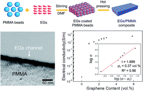
Highly conductive polymer composites were fabricated with a novel type of graphene-based filler, electrochemically exfoliated graphene sheets (EGs) produced without conventional oxidation/reduction of graphene oxide (GO). The high electrical conductivity of 417 ± 83 S m−1 at a content loading of 5.8 vol% and a low percolation threshold of 0.37 vol% could be attainable. Microscopic and spectroscopic investigations demonstrated the effective dispersion of EG-fillers on the surface of polymer particles and visualized the actual conducting channel between the polymer matrices.

Polymer composite materials with enhanced electrical and mechanical properties have been explored upon synergetic effects of their comprising components, which are usually incorporated with a functional second-phase filler into polymer matrices.1–3 In particular, conductive polymer composites are considered to be a key material in electronic devices, actuators, sensors and electromagnetic interference shielding.4–7 As a promising filler in the conductive polymer composites, graphene, a single atomic layer of two-dimensional and conjugated carbon network, has recently stood in the spotlight due to its specific geometric features of large surface area and high aspect ratio in addition to its exceptional electrical, thermal and mechanical properties.3,8–19 In order for industrial implementation of graphene-based conductive polymer composites, bulk-quantity production of graphene should be first addressed while maintaining the excellent intrinsic electrical properties.

Despite conspicuous high-quality of graphene nanosheets fabricated via mechanical exfoliation, epitaxial growth and chemical vapour deposition,20–22 the high-temperature process, use of a sacrificial metal and multistep processing steps have substantially impeded these production routes to be used for the massive graphene production. In alternative, a solution-process based on chemical exfoliation of graphite into graphene oxide (GO) and the following reduction of GO into reduced GO (rGO) has opened a cost-effective way to the bulk-production of graphene.23–26 However, the chemical oxidation of graphite into GO inevitably results in covalent modification of aromatic carbon networks with various oxygen-containing groups such that significantly damage the crystalline layers of graphene, which degrades the unique properties of individual graphene sheets. Furthermore, the reduction process is prone to irreversibly aggregate rGO sheets that disturb homogeneous dispersion and incorporation of graphene fillers into the polymer matrices. Nevertheless, graphene-based polymer composites mainly have employed the rGO-based fillers reduced from GO.3,9–19

The trade-off between the production scale and the quality of graphene fillers can be compromised by a electrochemical exfoliation approach, which enables the massive production of high-quality graphene sheets due to its simple, high-yield and environmentally benign process.27–29 In the electrochemical exfoliation system, the gas species are evolved from electrochemical-potential-assisted oxidation of electrolyte at the edges and subsurface of graphite layers and induces the vertical and horizontal expansion and exfoliation of graphite layers into graphene sheets. As a result, the large-scale production of high-quality electrochemically exfoliated graphene sheets (EGs) provide a novel type of conducting fillers for highly conductive polymer composites.

Motivated by the attracting features of EGs, here, we incorporated the EG fillers into poly(methyl methacrylate) (PMMA) polymer matrices, which is a versatile polymer with the advantages of low price, optical transparency and mechanical strength.30,31 Without the conventional oxidation/reduction process to prepare the graphene-based fillers, the EGs/PMMA polymer composites showed the high electrical conductivity of 417 ± 83 S m−1 at a content loading of 5.8 vol%. The electrical transition of insulator-to-conductor was measured to occur at the low percolation threshold of 0.37 vol%. The critical exponent fitted by a scaling law indicates the electrical conduction of EGs/PMMA composites through 3-dimensional (3D) conducting EG-filler networks between the polymer matrices. Microscopic and spectroscopic investigations could demonstrate the effective dispersion of EG-fillers on the surface of polymer particles and visualized the actual conducting channel width to be a critical geometric parameter to explain the percolation behaviour.

EGs were electrochemically exfoliated in an aqueous solution of inorganic salt (ammonium sulfate, (NH4)2·SO4).29 A typical exfoliation process was carried out in a two electrode system containing the 0.1 M electrolyte solution where graphite foil (Alfa Aesar) and Pt foil used as anode and cathode, respectively. The positive DC potential applied to the anode was fixed to be 10 V. The as-obtained EGs were collected by vacuum filtration through an anodized aluminum oxide (AAO) membrane and rinsed with distilled water several times. Thin EGs could be obtained via dispersion of product into dimethylformamide (DMF) solvent using bath sonication for 10 min and a centrifuge at 4000 rpm for 10 min. After being centrifuged, the sediment of dispersion was decanted and the supernatant dispersion were collected, and used to fabricate the polymer composite. The final concentration of EG-dispersion was controlled to be 1 mg ml−1.

Morphology and thickness of EGs were characterized by atomic force microscopy (AFM). Fig. 1a presents a typical AFM image of EGs loaded onto a SiO2 substrate using the Langmuir–Blodgett technique.32 Most of EGs were measured to have lateral sizes in a range of 1–5 μm. A statistical profiling from the AFM height measurements of 100 EGs discloses that 65% of EGs are thinner than 6-layer of graphene (Fig. S1 in the ESI). The thickness of EGs could be roughly averaged to 5.02 nm (±2.06 nm). TEM image in Fig. 1b displays a few-layered EGs with the lateral size of approximately 3 μm consistent with those of EGs measured by the AFM technique. The selected area electron diffraction (SAED) pattern of EG shows the 6-fold symmetry of hexagonal crystalline structure (the inset of Fig. 1b). Chemical structure and composition of EGs was probed using X-ray photoelectron spectroscopy (XPS). The deconvolution of C 1s XPS peak (Fig. 1c) represents four carbon atomic components assigned to C–C (284.5 eV), C–O (286.3 eV), C[double bond, length as m-dash]O (289.1 eV) and O–C[double bond, length as m-dash]O (289.1 eV).33 The oxygen-functional groups on the basal and edges of graphene sheets has been reported to originate from the over-oxidation unavoidable during the electrochemical process.27,28 However, the carbon to oxygen ratio (C/O ratio) of the as-prepared EGs was measured to be 10.34, importantly, without the post-reduction step.


image file: c5ra04202j-f1.tif
Fig. 1 Morphology, thickness and chemical structure of EGs characterized using (a) AFM, (b) TEM and (c) XPS.

In order to investigate the electrical property of EGs, a free-standing EG film was fabricated through vacuum filtration and vacuum drying at 200 °C. The electrical conductivity of EG films was measured to be 2.12 × 10⁴ S m−1 using a 4-probe system. Here, it needs to be pointed out that the C/O ratio and the electrical conductivity of EGs are comparable with those of highly reduced rGO using a hydrohalic (HI) acid, which recently has been used to fabricate 3D interconnected graphene networks in highly conductive rGO/polystyrene (PS) composites.16,34

To fabricate the segregated networks of EG-fillers, the controlled volume of EG-dispersion was first mixed with PMMA particles with a radius of 20 μm in DMF by stirring for 2 h. The EG-coated PMMA particles were precipitated and the supernatant transparent DMF solvent were decanted. The mixture was vacuum-filtrated, transferred into a vacuum oven and dried to a powder. Finally, the as-prepared powder was hot-pressed at 200 °C into a pellet with a radius of 25 mm and thickness of 1 mm. The fabrication steps for the EGs/PMMA composites with the segregated networks of EGs are schematically drawn in Fig. 2.


image file: c5ra04202j-f2.tif
Fig. 2 Schematic illustration of EGs/PMMA composites with the segregated networks of EG-fillers.

Encapsulation of PMMA polymer particles with the EGs-fillers could be observed by scanning electron microscopy (SEM). In comparison with the bare surfaces of PMMA particles (Fig. 3a), the shagged surface of EGs/PMMA particle depicts the entire coating of EGs over the surface of PMMA particle (Fig. 3b). The following hot-press step localizes the fillers of EGs at the boundaries between the polymer particles and further form the continuous conducting regions or channels of EGs with the segregated distribution inside the insulating polymer matrices. As recognized in SEM images of Fig. 3c and d, the hot-pressed polyhedrons are covered with the overlapped and compacted multilayers of EGs. The layer of EGs stacked on the surface of PMMA particles were further confirmed by Raman spectroscopy. The Raman spectrum of EGs/PMMA particle (Fig. S2 in the ESI) shows a prominent G peak at ∼1575 cm−1 from the first-order scattering of E2g vibrational mode of sp2 carbon atoms associated with the degree of graphitization. On the other hand, the D band is observed at ∼1350 cm−1 related to the breathing mode of sp3 carbon atoms from the structural defects and partially disordered structures, such as edges and oxygen-functional groups.35 It was also seen that the graphene sheets exhibited a broad and up-shifted 2D band at around 2700 cm−1, which indicates a few-layered EGs. The ratio between the intensity of G and D peaks (ID/IG) was calculated to be 0.58 that is much lower than those of chemically or thermally reduced rGO indicates the high-quality of EGs.25,35,36


image file: c5ra04202j-f3.tif
Fig. 3 SEM observation of (a) the bare- and (b) the EG-encapsulated of unpressed PMMA particles, and (c) the bare- and (d) the EG-coated PMMA polyhedrons.

The direct current electrical conductivity of graphene/PMMA composites as a function of graphene volume fraction is shown in Fig. 4. According to the classical percolation theory, the electrical conductivity of the composites above the percolation threshold (φc) depends on the volume fraction of filler described by a scaling law:37

σ = σo(φφc)t
where σ is the electrical conductivity of composite, σo the electrical conductivity of filler, φ the volume fraction of filler, φc the percolation threshold and t is a critical exponent. At a percolation threshold, the fillers construct the interconnected networks of conducting paths throughout the insulating polymer matrices and thus induce a transition of insulator-to-conductor with a steep increase of electrical current of composites. The percolation in the EGs/PMMA composites was measured to occur at the filler concentration (φc) of 0.37 vol%. Above the percolation threshold, the electrical conductivity of composites rapidly rises up to 112 ± 62 S m−1 at the filler loading of 2.2 vol% and finally reaches 417 ± 83 S m−1 at 5.8 vol%, which is notably higher than those of previous rGO-based polymer composites.9–15 All values of percolation threshold and the electrical conductivity were averaged from five different samples. Plotting σ vs. (φφc) in double logarithmic coordinates results in the conductivity exponent (t) of 1.899 (the inset of Fig. 4), which relies on the dimensionality of composites. In a single percolation system, the calculated t value in range of 1.6–2 stands for the formation of 3-dimensional conductive networks, in which the electrons transport through the interfaces between the polymer matrices.37,38


image file: c5ra04202j-f4.tif
Fig. 4 Semi-log plot of electrical conductivity of the EGs/PMMA composites as a function of EG-filler content. The inset is a double-logarithmic plot of volume electrical conductivity σ versus (φφc) with the fitted parameter of t = 1.899, φc = 0.37 vol%.

In the segregated structure, the percolation behaviour parameterized by the percolation threshold (φc) and the critical exponent (t) primarily depends on dimensionality of fillers (the particle size, shape and aspect ratio) and the width of conducting channels filled with the fillers.39,40 The channel width of conducting EG filler in the hot-pressed EGs/PMMA composites was observed using a cross-sectional transmission electron microscopy (TEM) technique. The cross-sectional TEM image visualizes the graphene fillers with the actual conducting channel width of ∼23 nm between the PMMA polymer particles (Fig. S3 in the ESI).

The percolation threshold has been believed to be a complex function of the dimension, shape, size, local variation in concentration and spatial distribution of fillers. To be specific, the percolation model on the segregated composite structure suggested that the percolation threshold substantially depends on the particle size ratio and the conducting channel width of fillers.39,40 It seems reasonable that the thinner graphene fillers with the large lateral diameters are readily to build the specific conductive networks at a lower content loading than those made of thicker fillers. That is, the width of conducting channel localized between the polymer matrices is expected to be thinner, leading to the lower percolation threshold in the graphene/polymer composites. Such a relationship between the geometric factor and the percolation behaviour may be intuited by comparing the results of EGs/PMMA composites with those of rGO/PS and rGO/PMMA composites incorporated with 3D interconnected networks of HI-reduced and hydrazine (N2H4)-reduced rGO.16,17 Despite the compatible oxidation degree and the electrical conductivity of EG fillers with those of the HI-reduced and the N2H4-reduced rGO fillers, the rGO/PS and the rGO/PMMA composites exhibited the relatively lower percolation threshold of 0.15 vol% and 0.16 vol%, respectively. It is understood that the thin rGO fillers made of mono- and few-layered sheets readily form the relatively narrower channel than the EG-based channels with the average thickness of 5.02 nm (±2.06 nm). In addition, the interaction between the fillers and the polymer matrices seems to affect the formation of conductive channel. For instance, the rGO/PS and the rGO/PMMA composites were designed upon self-assembling of the fillers and the surface-modified polymer particles with the opposite surface charges supposed to induce the strong and effective adsorption of rGO sheets onto the surface of PS and PMMA particles.16,17 In contrary, both surfaces of EGs and the PMMA particles were measured to be negatively charged with a zeta potential of −32 mV and −15 mV, respectively. The different surface charges of PMMA particles used in this work and the rGO/PMMA composite may be explained by different acceptor number of the solvent dimethylformamide (DMF) and deionized water.41 The repulsive electrostatic interaction between EGs and the PMMA particles may play a role in the formation of the thicker conducting channel of loosely packed EGs, which may be just physically stacked during the drying process. As a result, the relatively higher percolation threshold and the lower electrical conductivity of EGs/PMMA composites could be achieved in comparison with those of rGO/PS and rGO/PMMA composite. Nevertheless, we believe that the approach of this work without the conventional oxidation/reduction steps of rGO would contribute to development of the highly conductive graphene-based polymer composites. The more systematic study on the relationship between the percolation behaviour and the geometric and electrical parameters is in progress.

In summary, a novel type of EG-fillers, which were electrochemically produced without the conventional oxidation/reduction steps of rGO, could be effectively incorporated into the highly conductive EG/sPMMA polymer composites. Microscopic and spectroscopic observations demonstrated the construction of 3D conducting EG-filler networks in the segregated structure between the polymer matrices. The as-fabricated EGs/PMMA composites exhibited the high electrical conductivity of 417 ± 83 S m−1 at a filler content of 5.8 vol% and the low percolation threshold of 0.37 vol%.

Acknowledgements

This work was supported by a grant from the Fundamental R&D Program for Core Technology of Materials (10050890, Chalcogenide nanostructure-based room-temperature (25 °C) H2 & H2S gas sensors with low power consumption) and under grant number 10038362 funded by the Ministry of Trade, Industry & Energy, Republic of Korea.

Notes and references

  1. K. Y. Chun, Y. Oh, J. Rho, J.-H. Ahn, Y.-J. Kim, H. R. Choi and S. Baik, Nat. Nanotechnol., 2010, 5, 853 CrossRef CAS PubMed.
  2. T. S. Hansen, K. West, O. Hassager and N. B. Larsen, Adv. Funct. Mater., 2007, 17, 3069 CrossRef CAS.
  3. S. Stankovich, D. A. Dikin, G. H. B. Dommett, K. M. Kohlhaas, E. J. Zimney, E. A. Stach, R. D. Piner, S. T. Nguyen and R. S. Ruoff, Nature, 2006, 442, 282 CrossRef CAS PubMed.
  4. K. S. Kim, Y. Zhao, H. Jang, S. Y. Lee, J. M. Kim, K. S. Kim, J.-H. Ahn, P. Kim, J.-Y. Choi and B. H. Hong, Nature, 2009, 457, 706 CrossRef CAS PubMed.
  5. Y. Hu, W. Chen, L. Lu, J. Liu and C. Chang, ACS Nano, 2010, 4, 3498 CrossRef CAS PubMed.
  6. B. Y. Lee, K. Heo, J. H. Bak, S. U. Cho, S. Moon, Y. D. Park and S. Hong, Nano Lett., 2008, 8, 4483 CrossRef CAS PubMed.
  7. J. Liang, Y. Wang, Y. Huang, Y. Ma, Z. Liu, J. Cai, C. Zhang, H. Gao and Y. Chen, Carbon, 2009, 47, 922 CrossRef CAS.
  8. Y. Zhu, S. Murali, W. Cai, X. Li, J. W. Suk, J. R. Potts and R. S. Ruoff, Adv. Mater., 2010, 22, 3906 CrossRef CAS PubMed.
  9. J. R. Potts, D. R. Dreyer, C. W. Bielawski and R. S. Ruoff, Polymer, 2011, 52, 5 CrossRef CAS.
  10. H. Kim, A. A. Abdala and C. W. Macosko, Macromolecules, 2010, 43, 6515 CrossRef CAS.
  11. M.-C. Hsiao, S.-H. Liao, Y.-F. Lin, C.-A. Wang, N.-W. Pu, H.-M. Tsai and C.-C. M. Ma, Nanoscale, 2011, 3, 1516 RSC.
  12. J. Du, L. Zhao, Y. Zeng, L. Zhang, F. Li, P. Liu and C. Liu, Carbon, 2011, 49, 1094 CrossRef CAS.
  13. H. Hu, G. Zhang, L. Xiao, H. Wang, Q. Zhang and Z. Zhao, Carbon, 2012, 50, 4596 CrossRef CAS.
  14. M. Yoonessi and J. R. Gaier, ACS Nano, 2010, 4, 7211 CrossRef PubMed.
  15. M. Li, C. Gao, H. Hu and Z. Zhao, Carbon, 2013, 65, 371 CrossRef.
  16. C. Wu, X. Huang, G. Wang, L. Lv, G. Chen, G. Li and P. Jiang, Adv. Funct. Mater., 2013, 23, 506 CrossRef.
  17. V. H. Pham, T. T. Dang, S. H. Hur, E. J. Kim and J. S. Chung, ACS Appl. Mater. Interfaces, 2012, 4, 2630 Search PubMed.
  18. Y.-T. Liu, M. Dang, X.-M. Xie, Z.-F. Wang and X.-Y. Ye, J. Mater. Chem., 2011, 21, 18723 RSC.
  19. Y.-T. Liu, X.-M. Xie and X.-Y. Ye, Carbon, 2011, 49, 3529 CrossRef CAS.
  20. K. S. Novoselov, A. K. Geim, S. V. Morozov, D. Jiang, Y. Zhang, S. V. Dubonos, I. V. Grigorieva and A. A. Firsov, Science, 2004, 306, 666 CrossRef CAS PubMed.
  21. C. Berger, Z. Song, X. Li, X. Wu, N. Brown, C. Naud, D. Mayou, T. Li, J. Hass, A. N. Marchenkov, E. H. Conrad, P. N. First and W. A. de Heer, Science, 2006, 312, 1191 CrossRef CAS PubMed.
  22. Y. Lee, S. Bae, H. Jang, S. Jang, S.-E. Zhu, S. H. Sim, Y. I. Song, B. H. Hong and J.-H. Ahn, Nano Lett., 2010, 10, 490 CrossRef CAS PubMed.
  23. W. S. Hummers Jr and R. E. Offeman, J. Am. Chem. Soc., 1958, 80, 1339 CrossRef.
  24. D. C. Marcano, D. V. Kosynkin, J. M. Berlin, A. Sinitskii, Z. Sun, A. Slesarev, L. B. Alemany, W. Lu and J. M. Tour, ACS Nano, 2010, 4, 4806 CrossRef CAS PubMed.
  25. S. Stankovich, D. A. Dikin, R. D. Piner, K. A. Kohlhaas, A. Kleinhammes, Y. Jia, Y. Wu, S. T. Nguyen and R. S. Ruoff, Carbon, 2007, 45, 1558 CrossRef CAS.
  26. D. R. Dreyer, S. Park, C. W. Bielawski and R. S. Ruoff, Chem. Soc. Rev., 2010, 39, 228 RSC.
  27. C.-Y. Su, A.-Y. Lu, Y. Xu, F.-R. Chen, A. N. Khlobystov and L.-J. Li, ACS Nano, 2011, 5, 2332 CrossRef CAS PubMed.
  28. K. Parvez, R. Li, S. R. Puniredd, Y. Hernandez, F. Hinkel, S. Wang, X. Feng and K. Müllen, ACS Nano, 2013, 7, 3598 CrossRef CAS PubMed.
  29. K. Parvez, Z.-S. Wu, R. Li, X. Liu, R. Graf, X. Feng and K. Müllen, J. Am. Chem. Soc., 2014, 136, 6083 CrossRef CAS PubMed.
  30. G. Chen, J. H. Li, S. Qu, D. Chen and P. Y. Yang, J. Chromatogr. A, 2005, 1094, 138 CrossRef CAS PubMed.
  31. G. X. Xu, J. Wang, Y. Chen, L. Y. Zhang, D. R. Wang and G. Chen, Lab Chip, 2006, 6, 145 RSC.
  32. X. Li, G. Zhang, X. Bai, X. Sun, X. Wang, E. Wang and H. Dai, Nat. Nanotechnol., 2008, 3, 538 CrossRef CAS PubMed.
  33. M. J. McAllister, J.-L. Li, D. H. Adamson, H. C. Schniepp, A. A. Abdala, J. Liu, M. H. Alonso, D. L. Milius, R. Car, R. K. Prud'homme and I. A. Aksay, Chem. Mater., 2007, 19, 4396 CrossRef CAS.
  34. S. Pei, J. Zhao, J. Du, W. Ren and H.-M. Cheng, Carbon, 2010, 48, 4466 CrossRef CAS.
  35. C. Mattevi, G. Eda, S. Agnoli, S. Miller, K. A. Mkhoyan, O. Celik, D. Mastrogiovanni, G. Granozzi, E. Garfunkel and M. Chhowalla, Adv. Funct. Mater., 2009, 19, 2577 CrossRef CAS.
  36. V. López, R. S. Sundaram, C. G. Navarro, D. Olea, M. Burghard, J. G. Herrero, F. Zamora and K. Kern, Adv. Mater., 2009, 21, 4683 CrossRef.
  37. D. Stauffer and A. Aharony, Introduction To Percolation Theory, Taylor and Francis, London, 1994 Search PubMed.
  38. J. F. Gao, Z. M. Li, Q. J. Meng and Q. Yang, Mater. Lett., 2008, 62, 3530 CrossRef CAS.
  39. M. O. Lisunova, Ye. P. Mamunya, N. I. Lebovka and A. V. Melezhyk, Eur. Polym. J., 2007, 43, 949 CrossRef CAS.
  40. Ye. Mamunya, A. Boudenne, N. Lebovka, L. Ibos, Y. Candau and M. Lisunova, Compos. Sci. Technol., 2008, 68, 1981 CrossRef CAS.
  41. W. W. Liu, J. N. Wang and X. X. Wang, Nanoscale, 2012, 4, 425 RSC.

Footnote

Electronic supplementary information (ESI) available: Statistical thickness distribution of EGs using AFM measurement, Raman spectrum of EGs/PMMA particles and cross-sectional TEM images. See DOI: 10.1039/c5ra04202j

This journal is © The Royal Society of Chemistry 2015
Click here to see how this site uses Cookies. View our privacy policy here.