Electrodeposited multi-walled carbon nanotubes on Ag-loaded TiO2 nanotubes/Ti plates as a new photocatalyst for dye degradation
Neda Mohaghegha,
Masoud Farajib,
Fereydoon Gobal*a and
Mohammad Reza Gholami*a
aDepartment of Chemistry, Sharif University of Technology, Azadi Ave., P.O. Box 11365-9516, Tehran, Iran. E-mail: gholami@sharif.edu; gobal@sharif.edu; Fax: +98-21-66029165; Tel: +98-21-66165314 Tel: +98-21-66165304
bDepartment of Chemistry, Urmia University, Urmia, Iran
First published on 13th May 2015
Abstract
MWCNTs/Ag/TiO2NTs plates were synthesized via electrochemical reduction of functionalized multiwalled carbon nanotubes (MWCNTs) on Ag/TiO2NTs. The loading of silver nanoparticles was carried out by electroless reduction of Ag1+ onto TiO2 nanotubes previously formed by anodizing titanium. The SEM analysis revealed that MWCNTs were loaded significantly on the as-prepared Ag/TiO2NTs, where nanoparticles of Ag had grown on the walls of TiO2NTs. The photocatalytic activity of the synthesized plates was evaluated by the photodegradation of Methyl Orange (MO) dye under UV light irradiation. The results indicated that the MWCNTs/Ag/TiO2NTs demonstrated improved efficiency for MO photodegradation in comparison with Ag/TiO2NTs and TiO2NTs. This is attributed to the efficient separation and transfer of photogenerated electron–hole pairs. The chemical oxygen demand of an MO dye solution as measured at specified time intervals provides a good idea about the degradation of MO.
1. Introduction
TiO2 is one of the most important photocatalysts because of its high durability, very low toxicity, chemical inertness and corrosion resistance. TiO2 has been applied as a photocatalyst for the removal of organic contaminants in water or air and for the formation of hydrogen through water splitting.1,2 There are some disadvantages with the use of powder TiO2 like stirring during the reaction and separation of the catalyst from the treated water after each run. Some systems have used sedimentation, centrifugation and filtration to recover highly dispersed and suspended catalyst particles as it is easy for smaller particles to stay suspended in water, penetrate through filtration materials and clog filter membranes.3 Among various types of TiO2, TiO2NTs/Ti plate fabricated by anodizing titanium can be used as a suitable photocatalyst because of its high surface area, thermal stability, controlled pore structure, relatively low cost and especially the excellent reusability relative to other powdery TiO2 nanomaterials.4,5 However, the photocatalytic efficiency of TiO2 and also TiO2NTs/Ti plate for degradation of dyes decrease substantially due to the high recombination ratio of photoinduced electrons (e−) and holes (h+) produced when irradiated under ultraviolet (UV) light.6,7 Therefore, in order to retard the recombination of the photogenerated electrons and holes, various strategies have been designed, including doping TiO2 with metals or nonmetals.8–11 MWCNTs or CNTs are recently discovered material with cylindrical structures that possess high mechanical strength, large specific surface areas and favorable electronic properties.12–14 These can prevent the recombination of electron–hole pairs by serving as an electron sink when used in conjunction with semiconductor materials.7,15,16 Moreover, it has been known that the deposition of Ag nanoparticles on TiO2 reduces the possibility of electron–hole recombination, enhances the absorption of visible light and increases the rate of electron transfer to the oxidant, resulting in the photocatalytic activity improvement of TiO2.4,17 It seems plausible that the growth of MWCNTs on Ag/TiO2 might lead to a synergetic effect on photodegradation process. Therefore, it is rationally desirable to prepare new catalyst based on Ag, MWCNTs and TiO2.In this work, MWCNTs/Ag/TiO2NTs/Ti plates were fabricated via electrodeposition of Ag onto the previously formed TiO2 nanotubes followed by the electrochemical reduction of functionalized MWCNTs onto its surface. The properties of fabricated plates were analyzed by X-ray diffraction (XRD), scanning electron microscopy (SEM) and electrochemical impedance spectroscopy (EIS). The photocatalytic activity was examined by the degradation of Methyl Orange (MO) under UV light irradiation and the experimental results were discussed. To the best of our knowledge, this work may be the first report about electro-deposition of functionalized MWCNTs on the substrate for photocatalytic applications.
2. Experimental
2.1. Reagents and apparatus
Raw MWCNTs (purity > 95%, surface area 198 m2 g−1) were purchased from Aldrich. Methyl orange (MO) (MW = 327.33 g mol−1, CI = 13![[thin space (1/6-em)]](https://www.rsc.org/images/entities/char_2009.gif) 025) provided by Iran Colour Research Centre, was used without further purification and selected as a probe material to study the photocatalytic performance of the fabricated catalysts. The chemical structure of MO dye is shown in Fig. 1.
025) provided by Iran Colour Research Centre, was used without further purification and selected as a probe material to study the photocatalytic performance of the fabricated catalysts. The chemical structure of MO dye is shown in Fig. 1.
Morphological studies were carried out by scanning electron microscope (Philips, Model XL30). Chemical compositions were determined by EDX in a scanning electron microscope (VEGA\\Tescan). The crystallographic structures of the materials were determined by X-ray diffraction (XRD). Impedance measurements were performed by Voltalab10 electrochemical system.
2.2. Preparation of the plates
![[thin space (1/6-em)]](https://www.rsc.org/images/entities/char_2009.gif) :
:![[thin space (1/6-em)]](https://www.rsc.org/images/entities/char_2009.gif) 25, vol%) + 0.5 wt% NH4F at room temperature in a two-electrode cell using platinum foil as a counter electrode. The anodized samples were further washed with DI water and ultrasonically cleaned for 60 s in DI water to remove surface debris and subsequently dried in air. Finally, the anodized samples were annealed at 450 °C for 2 h to form the anatase phase.
25, vol%) + 0.5 wt% NH4F at room temperature in a two-electrode cell using platinum foil as a counter electrode. The anodized samples were further washed with DI water and ultrasonically cleaned for 60 s in DI water to remove surface debris and subsequently dried in air. Finally, the anodized samples were annealed at 450 °C for 2 h to form the anatase phase.Ag was deposited onto TiO2NTs/Ti plates by the electroless procedure at room temperature in an ultrasonic bath. Firstly, the TiO2NTs/Ti plates were immersed into an ethanol bath containing 0.25 mM AgNO3 for 1 min and were subsequently transferred to a reducing aqueous bath containing 5 M NH3 and 0.02 M hydrazine hydrate for 2 min.
![[thin space (1/6-em)]](https://www.rsc.org/images/entities/char_2009.gif) :
:![[thin space (1/6-em)]](https://www.rsc.org/images/entities/char_2009.gif) 1 v/v) under reflux condition according to the previous work.18,19 Prior to the process, purified MWCNTs were sonicated in the acid solution for 2 h to open the agglomeration of nanotube and anchoring acid solution uniformly on the carbon surface. Thereafter, homogenized carbon solution was oxidized under reflux condition at 100 °C for 6 h to introduce functional groups. Five-fold dilution was then applied to the carbon solution to stop oxidation reaction. Stirring and decantation were consecutively conducted for five times and lastly washed with DI water by filtration until the pH of the resultant solution was approximately at 7. The obtained precipitates were finally dried in a vacuum oven at 60 °C and denoted as f-MWCNTs. The f-MWCNTs dispersed solutions were prepared by adding given amounts of f-MWCNTs powder to 50 mL of DI water and sonicated for 1 h to enhance exfoliation to separate f-MWCNTs particles from each other. Deposition of f-MWCNTs onto the Ag/TiO2NTs/Ti plates was carried out galvanostatically at a current density of −10 mA cm−2 for the duration of 3000 s where the electrolyte was 1.0 M KNO3 + 0.3 g L−1 exfoliated f-MWCNT solution.
1 v/v) under reflux condition according to the previous work.18,19 Prior to the process, purified MWCNTs were sonicated in the acid solution for 2 h to open the agglomeration of nanotube and anchoring acid solution uniformly on the carbon surface. Thereafter, homogenized carbon solution was oxidized under reflux condition at 100 °C for 6 h to introduce functional groups. Five-fold dilution was then applied to the carbon solution to stop oxidation reaction. Stirring and decantation were consecutively conducted for five times and lastly washed with DI water by filtration until the pH of the resultant solution was approximately at 7. The obtained precipitates were finally dried in a vacuum oven at 60 °C and denoted as f-MWCNTs. The f-MWCNTs dispersed solutions were prepared by adding given amounts of f-MWCNTs powder to 50 mL of DI water and sonicated for 1 h to enhance exfoliation to separate f-MWCNTs particles from each other. Deposition of f-MWCNTs onto the Ag/TiO2NTs/Ti plates was carried out galvanostatically at a current density of −10 mA cm−2 for the duration of 3000 s where the electrolyte was 1.0 M KNO3 + 0.3 g L−1 exfoliated f-MWCNT solution.2.3. Photocatalytic degradation of MO
MO was selected as the probe molecule to investigate the photocatalytic activity of the prepared catalysts because MO is chemically stable and persistent nitrogen containing dye pollutant. The photocatalytic experiments were carried out by vertically placing the prepared plates in a Pyrex reactor containing 100 mL of 10.0 mg L−1 MO equipped with a magnetic stirrer. A 125 W mercury lamp served as the source of UV light to trigger the photocatalytic reaction. This reactor set-up was surrounded by a circulating water jacket to keep the temperature constant within ±1.0 °C. Prior to irradiation, MO solution in the presence of prepared plates was stirred for 30 min in a darkroom to establish the adsorption/desorption equilibrium of MO dye on the photocatalyst surface to exclude the effect of the dye adsorption in the photodegradation process and then photocatalytic reaction was initiated. At specified time intervals (15 min), 3 mL samples were removed and MO concentration was determined from the absorbance change at the wavelength of 463 nm using spectrophotometric method. To further amplify the studies, the extent of degradation was also followed by chemical oxygen demand (COD) measurements via titration of MO solution with KMnO4 solution at specified time intervals.3. Results and discussion
3.1. Structural and morphological characterization
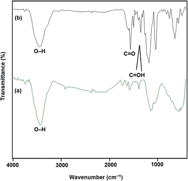
The FT-IR spectra of both MWCNTs and functionalized MWCNTs are shown in Fig. 2. The absorption band at 1600 cm−1 is ascribed to the C![[double bond, length as m-dash]](https://www.rsc.org/images/entities/char_e001.gif) C bond of the hexagonal network in MWCNTs. After the oxidation in acidic media, new bands appear. The peaks at 1730 cm−1, 3400 cm−1 and bands from 1380–1460 cm−1 are attributed to the stretching of C
C bond of the hexagonal network in MWCNTs. After the oxidation in acidic media, new bands appear. The peaks at 1730 cm−1, 3400 cm−1 and bands from 1380–1460 cm−1 are attributed to the stretching of C![[double bond, length as m-dash]](https://www.rsc.org/images/entities/char_e001.gif) O bond, O–H and the stretching modes of the C
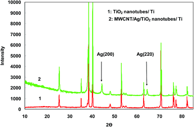
O bond, O–H and the stretching modes of the C![[double bond, length as m-dash]](https://www.rsc.org/images/entities/char_e001.gif) OH bonds of carboxylic acid, respectively. Hence, the presence of carbonyl and carboxylic acid groups on the surface of MWCNTs confirms the efficiency of oxidizing process. These functional groups can be efficiently reduced electrochemically at room temperature where no extra chemicals are employed and the thickness and amount of MWCNT film can also be best controlled. The chemical states of elements in the Ag particles coated TiO2 nanotube were analyzed by X-ray photoelectron spectroscopy (XPS). Fig. 3 shows the survey XPS spectrum of the Ag nanoparticles coated TiO2 nanotube and high-resolution XPS spectrum of Ag 3d. The survey spectrum (Fig. 3a) clearly indicates that three major sets of peaks from the O 1s, Ti 2p and Ag 3d states exist in the Ag nanoparticle coated TiO2 nanotube sample by electroless deposition. A high-resolution XPS spectrum confined to the Ag window (Fig. 3b) gave binding energies of Ag 3d doublet peaks located at 376.4 (Ag 3d3/2) and 371.0 (Ag 3d5/2) eV. This reveals that the Ag exists in a metallic form.20,21 The SEM images in Fig. 4 show significant differences in the morphologies of the investigated coatings. Fig. 4a exhibits the SEM image of bare TiO2NTs where distinct and well resolved nanotubes are visible. The inner diameter of TiO2NTs is 80–120 nm and the wall thickness is 20–30 nm. Fig. 4b displays SEM micrograph of the Ag-loaded TiO2NTs where Ag nanoparticles grown on the walls of TiO2NTs. The wall thickness of the Ag/TiO2NTs plates is 60–80 nm. Fig. 4c shows Ag/TiO2NTs structure coated well with f-MWCNTs by using the electro-deposition method. As seen in Fig. 4c, f-MWCNTs have been deposited on the surface of Ag/TiO2NTs. In order to probe the chemical compositions of prepared plates, the plate material was further characterized by EDX. Fig. 4d shows the EDX spectrum of the MWCNT/Ag/TiO2NTs/Ti plates that confirms the presence of both Ag and MWCNTs on TiO2NTs/Ti. As seen from Fig. 4d, Ti and C are the major elements which are originating from TiO2NTs/Ti and MWCNT, respectively and small amounts of elemental Ag identified at 2.984 keV. Fig. 5 displays XRD patterns of annealed TiO2NTs/Ti and MWCNTs/Ag/TiO2NTs/Ti plates prepared by the mentioned procedures. The peaks with 2θ of 25.3° and 48.2° are assigned to anatase crystal structure of TiO2NTs/Ti while lines at 40.4° and 38.5° correspond to the crystalline Ti metal. After deposition of MWCNTs and Ag, the pattern exhibits new peaks. The diffraction peaks at 44.5° and 64.5° correspond to Ag (200) and (220), respectively. It is clear that there are no diffraction peaks of MWCNTs in Fig. 5. This might be attributed to the presence of small amounts of non-crystalline MWCNTs thin films deposited on the Ag/TiO2NTs/Ti plates.
OH bonds of carboxylic acid, respectively. Hence, the presence of carbonyl and carboxylic acid groups on the surface of MWCNTs confirms the efficiency of oxidizing process. These functional groups can be efficiently reduced electrochemically at room temperature where no extra chemicals are employed and the thickness and amount of MWCNT film can also be best controlled. The chemical states of elements in the Ag particles coated TiO2 nanotube were analyzed by X-ray photoelectron spectroscopy (XPS). Fig. 3 shows the survey XPS spectrum of the Ag nanoparticles coated TiO2 nanotube and high-resolution XPS spectrum of Ag 3d. The survey spectrum (Fig. 3a) clearly indicates that three major sets of peaks from the O 1s, Ti 2p and Ag 3d states exist in the Ag nanoparticle coated TiO2 nanotube sample by electroless deposition. A high-resolution XPS spectrum confined to the Ag window (Fig. 3b) gave binding energies of Ag 3d doublet peaks located at 376.4 (Ag 3d3/2) and 371.0 (Ag 3d5/2) eV. This reveals that the Ag exists in a metallic form.20,21 The SEM images in Fig. 4 show significant differences in the morphologies of the investigated coatings. Fig. 4a exhibits the SEM image of bare TiO2NTs where distinct and well resolved nanotubes are visible. The inner diameter of TiO2NTs is 80–120 nm and the wall thickness is 20–30 nm. Fig. 4b displays SEM micrograph of the Ag-loaded TiO2NTs where Ag nanoparticles grown on the walls of TiO2NTs. The wall thickness of the Ag/TiO2NTs plates is 60–80 nm. Fig. 4c shows Ag/TiO2NTs structure coated well with f-MWCNTs by using the electro-deposition method. As seen in Fig. 4c, f-MWCNTs have been deposited on the surface of Ag/TiO2NTs. In order to probe the chemical compositions of prepared plates, the plate material was further characterized by EDX. Fig. 4d shows the EDX spectrum of the MWCNT/Ag/TiO2NTs/Ti plates that confirms the presence of both Ag and MWCNTs on TiO2NTs/Ti. As seen from Fig. 4d, Ti and C are the major elements which are originating from TiO2NTs/Ti and MWCNT, respectively and small amounts of elemental Ag identified at 2.984 keV. Fig. 5 displays XRD patterns of annealed TiO2NTs/Ti and MWCNTs/Ag/TiO2NTs/Ti plates prepared by the mentioned procedures. The peaks with 2θ of 25.3° and 48.2° are assigned to anatase crystal structure of TiO2NTs/Ti while lines at 40.4° and 38.5° correspond to the crystalline Ti metal. After deposition of MWCNTs and Ag, the pattern exhibits new peaks. The diffraction peaks at 44.5° and 64.5° correspond to Ag (200) and (220), respectively. It is clear that there are no diffraction peaks of MWCNTs in Fig. 5. This might be attributed to the presence of small amounts of non-crystalline MWCNTs thin films deposited on the Ag/TiO2NTs/Ti plates.
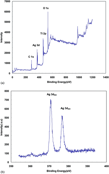 | ||
| Fig. 3 XPS analysis of the Ag/TiO2NTs/Ti: (a) the survey XPS spectrum and (b) the high-resolution spectrum for the Ag 3d states. | ||
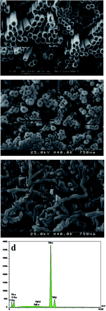 | ||
| Fig. 4 SEM images of bare (a) TiO2NTs/Ti, (b) Ag/TiO2NTs/Ti, (c) MWCNTs/Ag/TiO2NTs/Ti and (d) EDX spectra obtained of MWCNTs/Ag/TiO2NTs/Ti plate. | ||
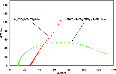
Electrochemical impedance spectroscopy (EIS) was used to study the role of MWCNTs in the photocatalytic performance of Ag/TiO2NTs/Ti. Fig. 6 shows the Nyquist plots of the prepared plates at the open circuit potential (OCP) in the frequency range of 100 kHz to 10 mHz in aqueous solution containing 10 mM K3[Fe(CN)6]![[thin space (1/6-em)]](https://www.rsc.org/images/entities/char_2009.gif) :
:![[thin space (1/6-em)]](https://www.rsc.org/images/entities/char_2009.gif) K4[Fe(CN)6] (1
K4[Fe(CN)6] (1![[thin space (1/6-em)]](https://www.rsc.org/images/entities/char_2009.gif) :
:![[thin space (1/6-em)]](https://www.rsc.org/images/entities/char_2009.gif) 1) and 0.1 M KCl. The plots consist of an overall distorted semicircle which can be attributed to the existence of two double layers in the interface of Ag/TiO2NTs and MWCNTs/Ag/TiO2NTs with electrolyte. The impedance at high frequencies and the diameter of the semicircle represent ohmic resistance (Rs) and total charge transfer resistance (Rct) in the plates, respectively. As seen from Fig. 6, MWCNTs/Ag/TiO2NTs/Ti plate possesses lower Rct and Rs than Ag/TiO2NTs/Ti plate, which is due to the conductive network formed by MWCNTs. The low values of Rs and Rct for MWCNTs/Ag/TiO2NTs/Ti plate indicate MWCNTs were chemically bonded on Ag/TiO2NTs/Ti. Also, both the electron accepting and transporting properties of MWCNT in the composite could contribute to the suppression of charge recombination, and thereby a higher rate in the photocatalysis would be achieved.
1) and 0.1 M KCl. The plots consist of an overall distorted semicircle which can be attributed to the existence of two double layers in the interface of Ag/TiO2NTs and MWCNTs/Ag/TiO2NTs with electrolyte. The impedance at high frequencies and the diameter of the semicircle represent ohmic resistance (Rs) and total charge transfer resistance (Rct) in the plates, respectively. As seen from Fig. 6, MWCNTs/Ag/TiO2NTs/Ti plate possesses lower Rct and Rs than Ag/TiO2NTs/Ti plate, which is due to the conductive network formed by MWCNTs. The low values of Rs and Rct for MWCNTs/Ag/TiO2NTs/Ti plate indicate MWCNTs were chemically bonded on Ag/TiO2NTs/Ti. Also, both the electron accepting and transporting properties of MWCNT in the composite could contribute to the suppression of charge recombination, and thereby a higher rate in the photocatalysis would be achieved.
3.2. Photocatalytic experiments
 | (1) |
The enhanced photocatalytic activity is governed by three main factors: (1) improved adsorbing affinity toward organic molecules, (2) increased light absorption and (3) effective charge carrier transfer and separation. Surface area, separation and transfer of charge carriers are the most influential factors in controlling both the rate and efficiency of photocatalysis.22–25
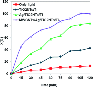
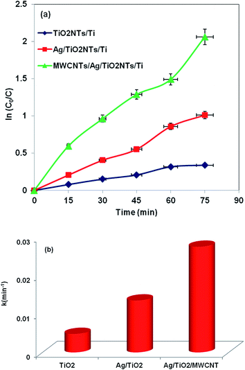
The results presented in Fig. 7 indicated that the modified MWCNTs/Ag/TiO2NTs/Ti displays significant improvement compared to the pure TiO2NTs/Ti and Ag/TiO2NTs/Ti samples under UV light irradiation. This could be rationalized on two grounds. Firstly, the interactions between MO and the MWCNTs may lead to the higher adsorption capacity of MWCNTs/Ag/TiO2NTs/Ti via higher π-conjugations. Secondly, the transportation and mobility of photogenerated electrons in the MWCNTs are very rapid in the π-conjugated of MWCNT structures; thus the efficient electron transfer facilitates the separation of photogenerated e−/h+ pairs. Facilitating their usage in catalytic process contribute to the superior photocatalytic activity of the modified MWCNTs/Ag/TiO2NTs/Ti sample.
For the Ag/TiO2NTs/Ti sample, the photocatalysis results also showed that it was more active than pure TiO2NTs/Ti. The higher photocatalytic efficiency may be ascribed to the silver particles that can reduce e−/h+ recombination rate by accommodating photogenerated electrons. Silver nanoparticle (Ag) has a higher work function than TiO2, 4.65 versus 4.2 eV.26 So, Ag deposited on the TiO2 nanotubes could markedly act as electron trappers to reduce the e−/h+ recombination rate and improve the photocatalytic activity. The reason for higher activity of TiO2NTs/Ti loaded with Ag nanoparticles can be explained via the Schottky barrier formed at the metal/semiconductor interface.26,27 It plays a key role as an effective electron trap to prevent e−/h+ recombination in the photocatalysis process. Fig. 8 presents the consumption of MO in the presence of MWCNTs/Ag/TiO2NTs/Ti with time as signified by the light absorption.
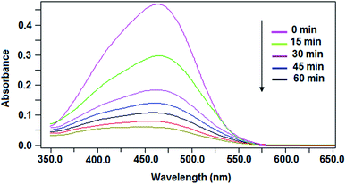 | ||
| Fig. 8 Typical absorbent spectra of the MO solution illuminated by UV light at different times in the presence of MWCNTs/Ag/TiO2NTs/Ti. | ||
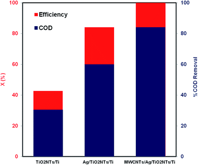
To further investigate the photocatalytic activity of the fabricated samples, the COD test was carried out. COD has been extensively used as an efficient technique to estimate the organic strength of wastewater. The COD test enables measurement of waste in terms of the total oxygen quantity needed for the oxidation of organic molecules to CO2 and H2O. The results demonstrate that the most active photocatalyst was MWCNTs/Ag/TiO2NTs/Ti as displayed in Fig. 9. The decrease in the COD values of the treated MO solution shows that the mineralization of MO occurs along with the colour removal. A maximum of 84% of the degradation efficiency was gained by MWCNTs/Ag/TiO2NTs/Ti photocatalyst in the present study, which is acceptable.
 | (2) |
 | (3) |
4. Conclusions
The novel samples developed in this study are new photocatalysts working under UV light irradiation. The prepared photocatalysts demonstrate high photocatalytic activity with respect to MO in aqueous solution. Evidence indicates that Ag/TiO2NTs/Ti is photoactive component and that MWCNTs species are probably contributing to facilitate both electron transfer and electrical conductivity. Due to the superior specific properties, new MWCNTs/Ag/TiO2NTs/Ti promotes its practical application in addressing various environmental issues. To the best of our knowledge, this is the first example in which MWCNTs/Ag/TiO2NTs/Ti plates have been used as the photocatalysts for MO degradation.References
- K. Cendrowski, M. Jedrzejczak, M. Peruzynska, A. Dybus, M. Drozdzik and E. Mijowska, J. Alloys Compd., 2014, 605, 173–178 CrossRef CAS PubMed.
- W. Liu, X. Wang, J. Song, Q. Zhang and C. T. Chang, Mater. Sci. Semicond. Process., 2014, 27, 273–279 CrossRef CAS PubMed.
- F. Han, V. S. R. Kambala, M. Srinivasan, D. Rajarathnam and R. Naidu, Appl. Catal., A, 2009, 359, 25–40 CrossRef CAS PubMed.
- X. Fan, J. Fan, X. Hu, E. Liu, L. Kang, C. Tang, Y. Ma, H. Wu and Y. Li, Ceram. Int., 2014, 40, 15907–15917 CrossRef CAS PubMed.
- L. Zong, Q. Li, J. Zhang, X. Wang and J. Yang, J. Nanopart. Res., 2013, 15, 2042–2051 CrossRef.
- S. Takenaka, T. Arike, H. Matsune and M. Kishida, Appl. Catal., B, 2012, 125, 358–366 CrossRef CAS PubMed.
- S. Wang, Q. Gong, Y. Zhu and J. Liang, Appl. Surf. Sci., 2009, 255, 8063–8066 CrossRef CAS PubMed.
- M. A. Barakat, H. Schaeffer, G. Hayes and S. Ismat-Shah, Appl. Catal., B, 2005, 57, 23–30 CrossRef CAS PubMed.
- J. C. Colmenares, M. A. Aramend, A. Marinas, J. M. Marinas and F. J. Urbano, Appl. Catal., A, 2006, 306, 120–127 CrossRef CAS PubMed.
- C. Burda, Y. Lou, X. Chen, A. C. S. Samia, J. Stout and J. L. Gole, Nano Lett., 2003, 3, 1049–1051 CrossRef CAS.
- M. Maicu, M. C. Hidalgo, G. Colón and J. A. Navio, J. Photochem. Photobiol., A, 2011, 217, 275–283 CrossRef CAS PubMed.
- S. Chatterjee, F. A. Nuesch and B. T. T. Chu, Nanotechnology, 2011, 22, 275714–275722 CrossRef CAS PubMed.
- A. Kongkanand and P. V. Kamat, ACS Nano, 2007, 1, 13–21 CrossRef CAS PubMed.
- J. Yu, T. Ma and S. Liu, Phys. Chem. Chem. Phys., 2011, 13, 3491–3501 RSC.
- S. K. Yadav, S. R. Madeshwaran and J. W. Cho, J. Colloid Interface Sci., 2011, 358, 471–476 CrossRef CAS PubMed.
- L. C. Juang, G. U. Semblante, S. J. You and S. H. Hong, J. Taiwan Inst. Chem. Eng., 2013, 44, 432–437 CrossRef CAS PubMed.
- J. S. Zhong, Q. Y. Wang and Y. F. Yu, J. Alloys Compd., 2015, 620, 168–171 CrossRef CAS PubMed.
- Y. M. Dai, W. J. Liu, T. C. Pan and J. M. Jehng, Appl. Surf. Sci., 2012, 258, 3027–3032 CrossRef CAS PubMed.
- J. Zhang, H. Zou, Q. Qing, Y. Yang, Q. Li, Z. Liu, X. Guo and Z. Du, J. Phys. Chem. B, 2003, 107, 3712–3718 CrossRef CAS.
- Y. Lai, H. Zhuang, K. Xie, D. Gong, Y. Tang, L. Sun, C. Lin and Z. Chen, New J. Chem., 2010, 34, 1335–1340 RSC.
- Y. Lai, Y. Chen, H. Zhuang and C. Lin, Mater. Lett., 2008, 62, 3688–3690 CrossRef CAS PubMed.
- N. Mohaghegh, M. Tasviri, E. Rahimi and M. R. Gholami, Mater. Sci. Semicond. Process., 2014, 21, 167–179 CrossRef CAS PubMed.
- H. Zhang, P. Xu, G. Du, Z. Chen, K. Oh, D. Pan and Z. Jiao, Nano Res., 2011, 4, 274–283 CrossRef CAS PubMed.
- L. C. Chen, Y. C. Ho, W. S. Guo, C. M. Huang and T. C. Pan, Electrochim. Acta, 2009, 54, 3884–3891 CrossRef CAS PubMed.
- N. Mohaghegh, M. Tasviri, E. Rahimi and M. R. Gholami, RSC Adv., 2015, 5, 12944–12955 RSC.
- Y. C. Liang, C. C. Wang, C. C. Kei, Y. C. Hsueh, W. H. Cho and T. P. Perng, J. Phys. Chem. C, 2011, 115, 9498–9502 CAS.
- I. Paramasivam, J. M. Macak and P. Schmuki, Electrochem. Commun., 2008, 10, 71–75 CrossRef CAS PubMed.
- D. Sarkar, C. K. Ghosh, S. Mukherjee and K. K. Chattopadhyay, ACS Appl. Mater. Interfaces, 2013, 5, 331–337 CAS.
| This journal is © The Royal Society of Chemistry 2015 |


