Metal–organic nanofibers as anodes for lithium-ion batteries†
Chongchong Zhaoab,
Cai Shen*a and
Weiqiang Han*a
aNingbo Institute of Materials Technology & Engineering, Chinese Academy of Sciences, 1219 Zhongguan Road, Zhenhai District, Ningbo, Zhejiang, China. E-mail: shencai@nimte.ac.cn; wqhan@nimte.ac.cn; Fax: +86-574-87910728; Tel: +86-574-86682743
bSchool of Materials Science and Engineering, Xiangtan University, Hunan 411105, China
First published on 10th February 2015
Abstract
Metal organic nanofibers (MONFs) synthesized from precursors of amino acid and copper nitrate were applied as anode materials for Li-ion batteries. Excellent cyclic stability as well as a moderate reversible capacity within the voltage range of 0.01–3.0 V were obtained (ca. 233 mA h g−1 at a current density of 50 mA g−1 following 200 cycles).
Introduction
Lithium-ion batteries (LIBs) are now widely considered as the most promising chemical power sources for electric vehicles and large-scale energy storage.1–5 The state-of-the-art of anodes employed in LIBs are made of graphite because of their high electrical conductivity and good electrochemical performance. However, in many cases, they are prepared though energy-intensive processes. Moreover, Li-plating on graphite during discharge still poses safety issues. Silicon is another attractive material for anodes due to its high theoretical capacity (4200 mA h g−1). However, upon cycling, large volumetric changes lead to mechanical stresses which cause severe cracking and degradation of the material. The spinel Li4Ti5O12 (LTO) accommodates one lithium atom per formula unit (corresponding to a theoretical capacity of 175 mA h g−1), and has been proposed as one of the potential alternatives for graphite anodes due to its prolonged cycle performance due to zero structural change during the charge–discharge process.6–9 However, compared to graphite anodes, LTO has a relatively high voltage of ∼1.55 V versus lithium metal, which in turn leads to low power for battery systems.10Metal–organic frameworks (MOFs), constructed by metal ions and electron-donating organic ligands in a three dimensional space, has been emerging as a class of promising materials for gas separation, catalysis, and drug storage and delivery.11–19 Recently, MOFs or Prussian blue analogies (PBs) have been explored as new framework of electrode materials for LIBs or sodium-ion batteries.20–23 Chen et al. reported the use of MOF-177 (Zn4O(1,3,5-benzenetribenzoate)2) as anodes for lithium ion batteries.22 The anode exhibits a relatively high irreversible capacity in the first discharge process and a low capacity of ∼100 mA g h−1 after the second discharge. The large capacity fade was explained by the structure damage of MOF-177 during the charge–discharge process. A conversion reaction regarding the Li storage was proposed. Tarascon et al. reported the first example of mixed-valence MOF [FeIII(OH)0.8F0.2(O2CC6H4CO2)] (MIL-53(Fe)) as cathode for Li storage.21 It was found that the percentage of the FeII component increased as Li inserted into the sample, and returns to close to zero as the sample is fully recharged. However, capacity of only 75 mA h g−1 was obtained due to the limited number of inserted Li atoms per formula unit (0.6). J. Vittal et al. reported the lithium storage in a MOF with diamondoid topology [Zn3(HCOO)6] and concluded that during charge, Zn–MOF react with Li+ to form Zn nanoparticles, and then Li–Zn alloy.24 A capacity of 560 mA h g−1 can be obtained for up to 60 cycles with a 60 mA g−1 charging rate within the voltage range 0.005–3.0 V. However, no further cycling performance was reported probably due to the degradation of MOFs.
We aim to develop novel MOFs materials with long cycling performance as electrode for lithium storage. In this work, we use environmental friendly materials, aspartic acid (Asp, an amino acid) and copper nitrate to prepare a metal–organic nanofiber (MONF, Scheme 1). The synthesized MONF shows excellent cyclic stability as well as moderate reversible capacity, which make it a potential candidate as novel anode materials for energy storage.
 | ||
| Scheme 1 Schematic illustration of the preparation of amino acid–Cu nanofibers as electrode materials for lithium-ion batteries. | ||
Experimental
The metal–organic nanofiber was prepared by the following steps: firstly, an aqueous solution of Cu(NO3)2·6H2O (4.5 mmol, 6 ml) was added to a 30 ml aqueous solution containing a mixture of NaOH (6 mmol) and aspartic acid (3 mmol) at room temperature. The solution immediately turned into a deep blue colour and the growth of blue flocculent was observed. The solution was then washed six times with distilled water and ethanol solution (1![[thin space (1/6-em)]](https://www.rsc.org/images/entities/char_2009.gif) :
:![[thin space (1/6-em)]](https://www.rsc.org/images/entities/char_2009.gif) 1), followed by centrifugation. The product was dried in a vacuum oven at 80 °C for 10 h. The morphology and microstructure of the MONFs was investigated by scanning electron microscopy (SEM, S-4800, Hitachi) and X-ray diffraction (XRD, D8 Discover, Broker AXS, Cu radiation, λ = l.540596 Å). Thermogravimetric analysis (Perkin–Elmer, Pyris Diamond TG/DTA) and nitrogen adsorption–desorption techniques (Micromeritics, ASAP 2020M) were used to analyze the thermal stability and structure of metal organic nanofibers.
1), followed by centrifugation. The product was dried in a vacuum oven at 80 °C for 10 h. The morphology and microstructure of the MONFs was investigated by scanning electron microscopy (SEM, S-4800, Hitachi) and X-ray diffraction (XRD, D8 Discover, Broker AXS, Cu radiation, λ = l.540596 Å). Thermogravimetric analysis (Perkin–Elmer, Pyris Diamond TG/DTA) and nitrogen adsorption–desorption techniques (Micromeritics, ASAP 2020M) were used to analyze the thermal stability and structure of metal organic nanofibers.
Electrochemical measurements were carried out using a 2032-type coin cell system. The composite anode electrodes were prepared by mixing 70 wt% active materials, 20 wt% conductive carbon black (super P), and 10 wt% polyvinylidene fluoride (PVDF). N-methyl-2-pyrrolidone (NMP) was used as solvent to form a slurry onto Cu current collectors. Metallic lithium was used as counter electrode, and Celgard 2400 polypropylene was used as separator. 1 M lithium hexafluorophosphate (LiPF6) in a mixture of fluoroethylene carbonate/ethyl methyl carbonate/dimethyl carbonate (FEC/EMC/DMC, 1![[thin space (1/6-em)]](https://www.rsc.org/images/entities/char_2009.gif) :
:![[thin space (1/6-em)]](https://www.rsc.org/images/entities/char_2009.gif) 1:
1:![[thin space (1/6-em)]](https://www.rsc.org/images/entities/char_2009.gif) 1 in volume ratio) were used as electrolytes. Charge–discharge measurements were carried out galvanostatically at various current densities over a voltage range of 0.01–3.0 V (vs. Li/Li+) using a commercial battery test system (LAND model, CT2001A) at 30 °C.
1 in volume ratio) were used as electrolytes. Charge–discharge measurements were carried out galvanostatically at various current densities over a voltage range of 0.01–3.0 V (vs. Li/Li+) using a commercial battery test system (LAND model, CT2001A) at 30 °C.
Results and discussion
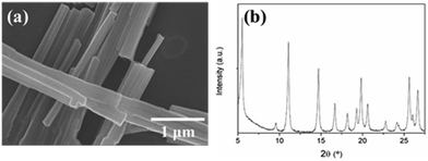
SEM image (Fig. 1a) of the Asp–Cu nanofibers clearly shows a very homogeneous sample of fiber structures. The diameter of each nanofiber ranges from 100 nm to 200 nm with length of several microns. X-ray powder diffraction performed on the Asp–Cu nanofibers confirmed their crystalline character (Fig. 1b). The relative broaden peak also confirmed nano scale size of the nanofibers.According to previous reported reaction mechanism, there are two carbonyl groups in Asp–Cu nanofibers available for reversible reaction with lithium ions, providing a theoretical capacity of 275 mA h g−1.1 The reaction process was shown in Scheme 2.
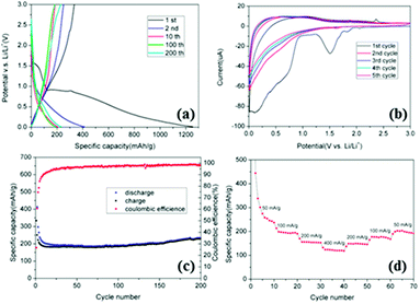
Experimentally, the electrochemical performance of the Asp–Cu nanofibers is shown in Fig. 2. Fig. 2a shows the galvanostatic discharge–charge curves for Asp–Cu nanofibers measured at a current density of 50 mA g−1. For the initial discharge, the potential drops sharply to ∼1.6 V, and then to a plateau of about 0.9 V versus Li/Li+, which can be attributed to the formation of solid electrolyte interface (SEI) film. The discharge process was then followed by a long and smooth slope below 0.9 V until the end of discharge. The initial discharge and charge capacity was found to be 1255 mA h g−1 and 334 mA h g−1, respectively, with a large irreversible capacity loss of more than 900 mA h g−1 due to the formation of the SEI film and the reaction of lithium with hydrated water.24 After the initial cycle, the large capacity loss value started to diminish and the capacity stabilized to a more or less value of 200 mA h g−1.
Fig. 2b shows the cyclic voltammograms (CVs) of the Asp–Cu nanofibers measured between 0.01 V and 3 V at a scan rate of 0.05 mV s−1. The results are in good agreement with the above discharge–charge curves. During the first cycle, intense cathodic (reduction, Li-insertion) peaks at 1.6 V correspond to the consumption of crystal water. The broad peak around 0.7–0.9 V was due to formation of the SEI. In the successive first anodic sweep (Li-extraction), there is a broad peak in the potential range of 0.2–1.3 V, which can be ascribed to the overall Li extraction.
The excellent cycling performance of the Asp–Cu nanofibers was demonstrated in Fig. 2c. Fig. 2c shows the cycling performance and the coulombic efficiency of Asp–Cu nanofibers electrodes measured at 50 mA g−1. The specific capacity of Asp–Cu nanofibers decreases in the first 10 cycles, and becomes very stable afterwards. The capacity even slightly increases upon further charge–discharge, which may be attributed to the fully utilization of the porous structure of Asp–Cu nanofibers. This can be explained by the fact that volume expansion and shrinkage of Asp–Cu nanofibers during charge–discharge opens the porosity of the Asp–Cu nanofibers and allows more electrolytes to penetrate into the entire electrode.1 It shortens the Li-ion diffusion pathway and enhances the utilization of electrode which resulted in the increase of capacity. The coulombic efficiency is only 26.6% in the initial cycle, indicating a large initial irreversible capacity which can be ascribed to the formation of SEI film and other loss of irreversible capacity. The coulombic efficiency then slowly increases to more than 98.5% after 200 cycles. This indicated an excellent reversible capacity of this electrode material for long term cycling. Fig. 2d illustrated the high rate capability of the Asp–Cu nanofibers electrode with the current density increases from 50 mA g−1 to 400 mA g−1. The highly reversible and symmetric pattern demonstrates the excellent rate capability and cycle stability.
It is interesting to note that for aspartic acid alone, the measured capacity of aspartic acid as active materials for electorde is only about 100 mA h g−1 under the same conditions (Fig. S1†). This indicated that the lithium sotrage mechanism is relative complicate. We propose that part of the lithium are stored in the pore sites of the MONFs. The pore structure and the surface area of the Asp–Cu nanofibers were investigated by adsorption–desorption isotherms (Fig. S6†), and the BET surface areas were calculated to be 41.33 m2 g−1, which is significantly higher than the graphite anodes (∼1–2 m2 g−1).25 However, how the pore size affects the lithium storage capability is still unknown. Large amonut of effort are required considering the fact that structural stability, type of metal and the linker of MOFs all affect the performance of the batteries.
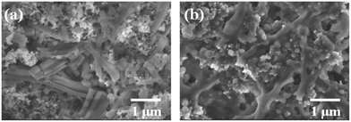
The surface morphology of the Asp–Cu nanofibers electrode before and after electrochemical cycling process was examined by SEM (Fig. 3). Clearly, after cycling the surface of the nanofibers is covered by a SEI film. No pulverization or disintegration of the nanofibers on the electrode surface can be observed, which explain the excellent cycling stability of the Asp–Cu nanofiber electrode.
 | ||
| Fig. 3 SEM images of the Asp–Cu nanofiber electrode: (a) before cycling; (b) after 200 cycles of charge–discharge. | ||
To further explore the lithium-storage of this type of material, other amino acids such as succinic acid and fumaric acid were also used to coordiante with copper ions to form stable MONFs (Fig. S2 and S3†). The cycling performance and coulombic efficiency of these MONFs was evaluated at a current densities of 100 mA g−1 over a range of 0.01–3 V versus Li/Li+ (Fig. S4†). It was found that both samples deliver a reversible capacity of ca. 120–140 mA g−1 with a coulombic efficiency of ca. 97.5% after 100 cycles. This result shows both MONFs has similar lithium storage ability as the Asp–Cu nanofibers regardless of the backbone functional group (i.e. conjugated carboxylate are not necessary for lithiation reaction).
Conclusions
We use environmental friendly materials, amino acid and copper nitrate to prepare metal organic nanofibers as anode materials for lithium-ion batteries. The obtained product demonstrates excellent cycling stability. A moderate reversible capacity of ca. 233 mA h g−1 at a current density of 50 mA g−1 after 200 cycles was achieved. The overall discharge potential is below 0.9 V, which is significantly lower than the Li4Ti5O12 materials. This study clearly shows that metal–organic framework structure could be good candidate electrode materials for energy storage.Acknowledgements
We thank the National Natural Science Foundation of China (Grant no. 51371186 and 21303236), the recruitment program of global experts of Central Organization Department, The Ningbo “3315 group plan” and the NIMTE (Y20838RA23, Y30805WA06 and Y30806RA05). Cai thanks the financial support from Ningbo “3315 individual plan”, the Youth Innovation Promotion Association, CAS, and SRF for ROCS, SEM.References
- C. Luo, R. M. Huang, R. Kevorkyants, M. Pavanello, H. X. He and C. S. Wang, Nano Lett., 2014, 14, 1596 CrossRef CAS PubMed.
- M. Armand, S. Grugeon, H. Vezin, S. Laruelle, P. Ribiere, P. Poizot and J. M. Tarascon, Nat. Mater., 2009, 8, 120 CrossRef CAS PubMed.
- W. Li, F. Wang, S. S. Feng, J. X. Wang, Z. K. Sun, B. Li, Y. H. Li, J. P. Yang, A. A. Elzatahry, Y. Y. Xia and D. Y. Zhao, J. Am. Chem. Soc., 2013, 135, 18300 CrossRef CAS PubMed.
- X. L. Wang, M. Feygenson, H. Y. Chen, C. H. Lin, W. Ku, J. M. Bai, M. C. Aronson, T. A. Tyson and W. Q. Han, J. Am. Chem. Soc., 2011, 133, 11213 CrossRef CAS PubMed.
- X. L. Wang, W. Q. Han, H. Y. Chen, J. M. Bai, T. A. Tyson, X. Q. Yu, X. J. Wang and X. Q. Yang, J. Am. Chem. Soc., 2011, 133, 20692 CrossRef CAS PubMed.
- C. F. Lin, B. Ding, Y. L. Xin, F. Q. Cheng, M. O. Lai, L. Lu and H. H. Zhou, J. Power Sources, 2014, 248, 1034 CrossRef CAS PubMed.
- S. G. Ri, L. Zhan, Y. Wang, L. H. Zhou, J. Hu and H. L. Liu, Electrochim. Acta, 2013, 109, 389 CrossRef CAS PubMed.
- H. Song, T. G. Jeong, Y. H. Moon, H. H. Chun, K. Y. Chung, H. S. Kim, B. W. Cho and Y. T. Kim, Sci. Rep., 2014, 4, 4350 Search PubMed.
- J. Liu, K. P. Song, P. A. van Aken, J. Maier and Y. Yu, Nano Lett., 2014, 14, 2597 CrossRef CAS PubMed.
- Y. M. Chen, Z. G. Lu, L. M. Zhou, Y. W. Mai and H. T. Huang, Energy Environ. Sci., 2012, 5, 7898 CAS.
- C. J. Lu, T. Ben, S. X. Xu and S. L. Qiu, Angew. Chem., Int. Ed., 2014, 53, 6454 CrossRef CAS PubMed.
- G. Xu, K. Otsubo, T. Yamada, S. Sakaida and H. Kitagawa, J. Am. Chem. Soc., 2013, 135, 7438 CrossRef CAS PubMed.
- I. Imaz, M. Rubio-Martinez, J. An, I. Sole-Font, N. L. Rosi and D. Maspoch, Chem. Commun., 2011, 47, 7287 RSC.
- A. Betard and R. A. Fischer, Chem. Rev., 2012, 112, 1055 CrossRef CAS PubMed.
- D. Bradshaw, A. Garai and J. Huo, Chem. Soc. Rev., 2012, 41, 2344 RSC.
- C. Shen, I. Cebula, C. Brown, J. L. Zhao, M. Zharnikov and M. Buck, Chem. Sci., 2012, 3, 1858 RSC.
- A. Dragasser, O. Shekhah, O. Zybaylo, C. Shen, M. Buck, C. Woll and D. Schlettwein, Chem. Commun., 2012, 48, 663 RSC.
- I. Cebula, C. Shen and M. Buck, Angew. Chem., Int. Ed., 2010, 49, 6220 CrossRef CAS PubMed.
- I. Imaz, M. Rubio-Martinez, W. J. Saletra, D. B. Amabilino and D. Maspoch, J. Am. Chem. Soc., 2009, 131, 18222 CrossRef CAS PubMed.
- M. Okubo and I. Honma, Dalton Trans., 2013, 42, 15881 RSC.
- G. Ferey, F. Millange, M. Morcrette, C. Serre, M. L. Doublet, J. M. Greneche and J. M. Tarascon, Angew. Chem., Int. Ed., 2007, 46, 3259 CrossRef CAS PubMed.
- X. X. Li, F. Y. Cheng, S. N. Zhang and J. Chen, J. Power Sources, 2006, 160, 542 CrossRef CAS PubMed.
- G. de Combarieu, M. Morcrette, F. Millange, N. Guillou, J. Cabana, C. P. Grey, I. Margiolaki, G. Ferey and J. M. Tarascon, Chem. Mater., 2009, 21, 1602 CrossRef CAS.
- K. Saravanan, M. Nagarathinam, P. Balaya and J. J. Vittal, J. Mater. Chem., 2010, 20, 8329 RSC.
- Z. M. Bharat and S. Chahar, EVS24 International Battery, Hybrid and Fuel Cell Electric Vehicle Symposium, Stavanger, Norway, May, 13, 2009 Search PubMed.
Footnote |
| † Electronic supplementary information (ESI) available. See DOI: 10.1039/c4ra16416d |
| This journal is © The Royal Society of Chemistry 2015 |


