
A photochromic nano-system via self-recovery for stable photocatalytic hydrogen evolution by optimizing TiO2 surface energy†
Jinghui Jiang,
Liping Tong,
Han Zhou*,
Fan Zhang,
Jian Ding,
Di Zhang and
Tongxiang Fan*
State Key Laboratory of Metal Matrix Composites, Shanghai Jiaotong University, Dongchuan Road 800, Shanghai 200240, P.R. China. E-mail: txfan@sjtu.edu.cn; hanzhou_81@sjtu.edu.cn; Fax: +86-21-3420-2749
First published on 23rd January 2015
Abstract
TiO2-based photocatalysts are promising candidates for photocatalytic hydrogen evolution that utilizes solar energy due to their low cost and high stability, but their activities are usually limited by the drawbacks of TiO2. Specifically, the fluctuation of surface energy, disturbed by light irradiation, can change the relative stability of the TiO2 exposed crystal faces, which has a great influence on the photocatalytic activity. Focusing on this problem, we built a bromine containing TiO2-based photochromic self-recovery system to immobilize bromine in the photocatalyst after photocatalysis. After a series of charge migration experiments, the photocatalysis of our photochromic system was clarified, and proved that TiO2 is the final electron accepter. This conclusion further emphasizes the importance of optimizing the TiO2 surface energy to promote TiO2-based photocatalysts. As a result, a sustained effect of reducing TiO2 surface energy can be achieved by repeating the bromine adsorption to harvest stable photocatalytic hydrogen evolution under ultraviolet and visible light irradiation.
Introduction
At a time when energy and environmental issues are taking a toll on human survival and development, photocatalytic hydrogen evolution, by splitting water with photocatalysts, is accepted as a new way to solve such issues as it can transfer light energy into chemical energy.1 TiO2-based photocatalysts, the most extensively studied materials, are widely used in the photolysis of water since TiO2 was found to be able to split water into hydrogen (H2) and oxygen (O2).2–4 Basically, the activity of TiO2-based photocatalysts largely depends on TiO2 due to its inherent shortcomings, such as its large band gap (3.2 eV for anatase) and quick recombination of charges. Moreover, the fluctuation of surface energy, disturbed by light irradiation, can change the relative stability of the TiO2 exposed crystal faces, especially those hydrogen evolution planes, such as anatase (101) facet,5 which has a great influence on photocatalytic activity; thus, stabilizing or even decreasing the TiO2 surface energy will helpful to maintain the performance of the photocatalysis. Up till now, modifying TiO2 by dopants, such as Ti3+ or semiconductor oxide,6,7 to overcome its band gap and charge recombination has been successfully achieved by previous studies, but achieving a sustained effect of stabilizing or even decreasing the TiO2 surface energy in repeating photocatalytic hydrogen evolution is still not an easy task. In response to this situation, exploring efficient solutions to repeatedly optimize the surface energy of TiO2 is essential to maintain the performance of the photocatalysis.As an efficient solution of boosting TiO2 activity, non-metallic atoms have been employed to retard the increase of surface energy on exposed TiO2 facets.8,9 Halogens, a class of non-metallic elements, are efficient in reducing the surface energy of TiO2 facets by adsorbing on them.10 However, reuse of halogens in repeated photocatalytic tests is still a problem due to the weak bonding of the halogen and TiO2 facets; as a result, halogens are easily released into the environment during the after-treatment. Herein, for the purpose of harvesting a sustained effect of reducing the TiO2 surface energy, an efficient solution of immobilizing halogens in the photocatalyst after photocatalysis is explored to maintain photocatalytic activity, save costs, and avoid environmental pollution.
Based on the above assertion, acetylacetone is utilized as a ligand to extract Ti3+ ions from titanium(III) chloride solution to prepare a titanium precursor without chlorine ions (the detailed process is listed in the Experimental section). Due to the absence of chlorine ions in the titanium precursor, silver bromide (AgBr) and cupric oxide (CuO) are employed to build a photochromic self-recovery system. The light yellow AgBr, decomposed by light irradiation, can regenerate again from black silver (Ag0) and dissociative bromine molecule (Br2) in the dark by CuO catalysis to achieve the cyclic process of color change – the photochromic effect.11,12 Contributing to this characteristic, a well distributed TiO2-based photochromic nano-system (TPN) can be synthesized by merging this photochromic system into the titanium precursor via a chemical synthesis step and one sintering process. Fortunately, AgBr can recover from the photolysis to achieve the goal of immobilization of Br− in TPN after photocatalysis. Meanwhile, Ag0, from AgBr photolysis, and CuO are also introduced to modify the structure of TiO2, in this way, to facilitate photon capture and charge separation.13–15 To the best of our knowledge, this strategy is novel, simple, and cost efficient in maintaining stable and highly efficient photocatalytic hydrogen evolution while avoiding environmental pollution due to the environment unfriendliness of Br2. Moreover, it also overcomes the significant shortcomings, such as non-uniform dispersion, weak component bonds, and limited interface, of the deposition–precipitation method – the strategy commonly employed in previous research.16
Experimental
Materials
Acetylacetone (liquid, 99.0%), isopropyl alcohol (liquid, 99.7%), toluene (liquid, 99.5%), titanium(III) chloride solution (liquid, 15.0%), potassium bromide (granular, 99.0%), silver nitrate (granular, 99.8%), and copper nitrate trihydrate (granular, 99.0%) were purchased from Sinopharm Chemical Reagent Co., Ltd and used without further purification. Ultrapure water with a resistivity of 18.25 MΩ was used throughout the experiments.Synthesis of TPN, TiO2/AgBr, TiO2/CuxO, and TiO2
In a typical process, titanium(III) chloride solution (20 ml, 0.0514 mol), acetylacetone (30 ml, 0.2886 mol), and toluene (30 ml, 0.2806 mol) are mixed and left to stand for 20 min to obtain an orange titanium precursor, before being washed three times by ultrapure water and moved into a 250 ml conical flask with a ground glass stopper. Next, copper nitrate trihydrate (0.0240 g, 99.34 μmol), silver nitrate (0.0200 g, 117.6 μmol), and potassium bromide (0.0150 g, 126.1 μmol) are dissolved by 0.5 ml ultrapure water and dispersed them into titanium precursor with the assistance of isopropyl alcohol (30 ml, 0.3913 mol) under dark. Later, oxygen was expelled from the mixture by bubbling high purity nitrogen through it for 5 min; then, the mixture solution was sealed in conical flask by ground glass stopper and dispersed by ultrasonic for 30 min. Next, the mixture was evaporated in the dark to obtain a black jelly-like product, which was collected and burnt in air at 500 °C for 3 h (ramp rate. 2 °C min−1).The preparation process for TiO2/AgBr, TiO2/CuxO, and TiO2 is the same as TPN, except for the addition of silver nitrate, potassium bromide, or copper nitrate trihydrate: specifically, adding silver nitrate and potassium bromide to form TiO2/AgBr, adding copper nitrate trihydrate to form TiO2/CuxO, and adding none of this to form TiO2.
Catalytic testing
Irradiation was performed at 25 °C using a 750 W Xe arc lamp. A flask with 100 ml of aqueous solution, including a sacrificial reagent (20% methanol solution) and 0.1 g of catalyst, was connected to a gas chromatography system. The flask was evacuated and purged with argon gas (Ar2) in turns for 20 min, and the stirred mixture was irradiated for 5 h or 25 h with periodic removal of gas samples. The gas samples were analyzed by a Varian gas chromatograph employing a Supelco molecular 60/80 sieve 5A column with Ar2 as the carrier gas and a thermal conductivity detector (TCD).Dark self-recovery
After photocataysis, the mixture solution without after-treatment is exposed to air with magnetic stirring for 4 h in the dark at room temperature; then, the recovered TPN is collected by centrifugation and dried at 60 °C in the dark for the next round of photocatalysis.Preparation of unrecovered TPN
After photocatalysis, the photocatalysts – unrecovered TPN, dispersed in the mixture, is immediately collected by centrifugation to discard the supernatant and dried under vacuum at 60 °C in the dark before the next round of photocatalysis.Electron spin resonance (ESR) testing
The as-prepared photocatalyst (0.01 g) is first dispersed in 10 ml of a 20% methanol solution to form a mixture, and it is injected into a capillary with a one millimeter diameter by syringe. Then, the capillary, filled with the mixture, is degassed and irradiated by a 250 W Xe arc lamp for 10 min at room temperature with an excitation distance of 10 cm. After irradiation, the sample is quickly placed in a test device at a temperature of 100 K in 10 second to collect the data with a center field of 3400 G.Characterization
XRD analysis was conducted on a Rigaku Ultima IV X-ray diffractometer with Cu kα radiation (λ = 1.5406 Å). TEM and HRTEM images were obtained on a JEOL 2100F operated at 200 kV. ESR spectra were recorded at 100 K on a Bruker BioSpin GmbH with a microwave frequency of 9.456 GHz and power of 2.11 mW. XPS data were collected by Axis Ultra DLD with a monochromator Al anode. UV-Vis spectra were recorded on Perkin Elmer Lambda 950.Results and discussion
The phase of the as-synthesized sample was investigated by powder X-ray diffraction (XRD) (see Fig. 1a), which confirms that the as-produced TPN contains TiO2 and AgBr. All the TiO2 diffraction peaks can be assigned to a tetragonal anatase structure with cell parameters a = 3.785 Å and c = 9.514 Å, space group I41/amd (JCPDS no. 21-1272), and all the AgBr diffraction peaks correspond to a cubic structure with cell parameters a = 5.774 Å, space group Fm![[3 with combining macron]](https://www.rsc.org/images/entities/char_0033_0304.gif) m (JCPDS no. 06-0438). X-ray photoelectron spectroscopy (XPS) (see Fig. 1b) confirms the existence of Cu2p, indicating that Cu2+ ions from copper nitrate trihydrate are successfully doped into pristine TPN. Specifically, the fitting analyses for the XPS high-resolution spectrum of Cu2p in original TPN (see Fig. S1a†) confirm that Cu2p are assigned to Cu+2p3/2 at 932.2 eV,17 Cu+2p1/2 at 952.3 eV,18 Cu2+2p3/2 at 933.9 eV,19 and Cu2+2p1/2 at 953.6 eV,18 indicating that CuO and Cu2O are coexisting in TPN to form the structure of TiO2/AgBr/CuxO (x = 1, 2). Furthermore, the fitting analyses for the XPS high-resolution spectrum of Ti2p in TPN (see Fig. S1b†) reveal that Ti3+ exists on the surface of the TiO2 apart from the main species of Ti4+2p3/2 at 458.7 eV and Ti4+2p1/2 at 464.4 eV.20,21
m (JCPDS no. 06-0438). X-ray photoelectron spectroscopy (XPS) (see Fig. 1b) confirms the existence of Cu2p, indicating that Cu2+ ions from copper nitrate trihydrate are successfully doped into pristine TPN. Specifically, the fitting analyses for the XPS high-resolution spectrum of Cu2p in original TPN (see Fig. S1a†) confirm that Cu2p are assigned to Cu+2p3/2 at 932.2 eV,17 Cu+2p1/2 at 952.3 eV,18 Cu2+2p3/2 at 933.9 eV,19 and Cu2+2p1/2 at 953.6 eV,18 indicating that CuO and Cu2O are coexisting in TPN to form the structure of TiO2/AgBr/CuxO (x = 1, 2). Furthermore, the fitting analyses for the XPS high-resolution spectrum of Ti2p in TPN (see Fig. S1b†) reveal that Ti3+ exists on the surface of the TiO2 apart from the main species of Ti4+2p3/2 at 458.7 eV and Ti4+2p1/2 at 464.4 eV.20,21
 | ||
| Fig. 1 (a) XRD pattern of pristine TPN obtained by one chemical synthetic step and further sintering at 500 °C for 3 h (AgBr diffraction peaks are marked by an asterisk); (b) XPS spectrum of TPN; (c) TEM image of TPN; (d) HRTEM image of a TPN particle (scale bar = 5 nm); (e)–(g): fast Fourier transform (FFT) patterns taken from zone 1, 2, and 3 in (d), respectively. | ||
To investigate in detail the shape and exposed crystal faces of TPN, transmission electron microscopy (TEM) and high-resolution transmission electron microscopy (HRTEM) images were collected. The as-synthesized TPN (see Fig. 1c) looks like irregular flakes with diameters of 20 to 40 nm. Fig. 1d is a typical HRTEM image for the as-synthesized TPN, which reveals the crystal lattice and the orientation of the lattice planes with respect to the crystal faces. Fig. 1e–g shows the fast Fourier transform (FFT) patterns taken from zones 1, 2, and 3 in d, respectively. We can calculate from Fig. 1e that zone 1 in Fig. 1d is anatase, and along the [010] direction presents (101) and (10![[1 with combining macron]](https://www.rsc.org/images/entities/char_0031_0304.gif) ) crystallographic planes with a lattice spacing of 0.351 nm. The indicated angle in the FFT image (see Fig. 1e) is 41.3°, which is identical to the theoretical values of the angle between {101} faces. This information confirms that anatase nanocrystals in TPN mainly expose {101} faces to offer photo-reduction sites for hydrogen evolution.5 Similarly, we can further confirm zone 2 and zone 3 in Fig. 1d are AgBr and CuO crystals with exposed crystallographic planes of (11) and (11), respectively.
) crystallographic planes with a lattice spacing of 0.351 nm. The indicated angle in the FFT image (see Fig. 1e) is 41.3°, which is identical to the theoretical values of the angle between {101} faces. This information confirms that anatase nanocrystals in TPN mainly expose {101} faces to offer photo-reduction sites for hydrogen evolution.5 Similarly, we can further confirm zone 2 and zone 3 in Fig. 1d are AgBr and CuO crystals with exposed crystallographic planes of (11) and (11), respectively.
Since TiO2, CuxO, and AgBr are coexisting in TPN, ESR at 100 K was employed to confirm that TiO2 is the final electron acceptor in TPN during photocatalysis. This is the premise of studying the effectiveness of Br2 on TiO2 photocatalytic activity by excluding the possibility of CuxO or AgBr photocatalytic hydrogen evolution. Compared to samples without light irradiation (see Fig. S2a†), the enhanced paramagnetic signals of the irradiated samples (see Fig. 2a) indicate a series of charge transfer processes took place in TPN during light irradiation. The spectra of irradiated TiO2 and TiO2/AgBr (see spectra 1 and 2 in Fig. 2a) were collected to investigate the influence of AgBr on charge transfer. Obviously, the signal at g = 1.992, the characteristic signal of Ti3+,22 in spectrum TiO2/AgBr is largely enhanced, indicating that Ag0, from AgBr photolysis (see Fig. S3†), can efficiently boost Ti3+ trapping electrons; specifically, Ag0 not only can provide photon capture sites to trap photoelectrons, but it can form a Schottky barrier with TiO2 at their interface to facilitate electron transfer from Ag0 to TiO2 due to their work function (WF), (φAg = 4.25 eV, φTiO2 = 4.6 eV).23,24 Based on electron trapping, the marked signals in spectrum TiO2 with relative intensities of 1![[thin space (1/6-em)]](https://www.rsc.org/images/entities/char_2009.gif) :2:1 can be assigned to methanol radical [ĊH2O(H)], due to oxidation,25 which disappears in spectrum TiO2/AgBr. The most reasonable explanation is holes (h+) are trapped by Br− ions to generate Br2 molecules;26 thus, this signal will not arise in spectrum TiO2/AgBr before all the Br− ions are oxidized. This control experiment reveals that Ag0 can help TiO2 to harvest photoelectrons, and TiO2 is the final electron acceptor in TiO2/AgBr.
:2:1 can be assigned to methanol radical [ĊH2O(H)], due to oxidation,25 which disappears in spectrum TiO2/AgBr. The most reasonable explanation is holes (h+) are trapped by Br− ions to generate Br2 molecules;26 thus, this signal will not arise in spectrum TiO2/AgBr before all the Br− ions are oxidized. This control experiment reveals that Ag0 can help TiO2 to harvest photoelectrons, and TiO2 is the final electron acceptor in TiO2/AgBr.
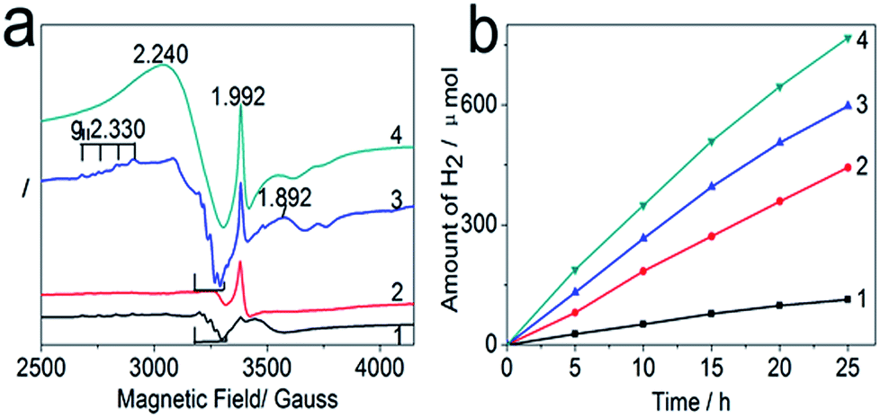 | ||
| Fig. 2 (a) ESR (X-band) spectra for four degassed titania-based photocatalysts in a 20% methanol solution measured at 100 K following Xe arc lamp irradiation for 10 min; (b) time course of evolved H2 for 0.1 g of as-prepared photocatalysts in 100 ml of 20% methanol solution under UV-Vis irradiation, respectively. (1 to 4 in (a) and (b) represent the samples of TiO2, TiO2/AgBr, TiO2/CuxO, and TPN, respectively). | ||
As for the influence of CuxO (x = 1, 2), some new signals emerge in spectrum TiO2/CuxO (see spectrum 3 in Fig. 2a), except the signal at g = 1.992 and the marked signals. Obviously, the signal at g = 1.992 in spectrum TiO2/CuxO is even stronger than that in spectrum TiO2/AgBr, indicating CuxO is more efficient than AgBr at facilitating Ti3+ trapping electrons. This strengthening should be contributed by the p–n junctions and conduction-band edges of TiO2 and CuxO (VCB,TiO2 = −0.52 eV, VCB,CuO = −0.3 eV, VCB,Cu2O = −1.13 eV),27–29 which facilitate the migration of photoelectrons from Cu2O to TiO2 when all CuO particles are reduced to Cu2O30 (see spectrum 2 in Fig. S4†); as a result, more electrons will enrich in TiO2 due to the increase of visible light absorption by Cu2O doping. Furthermore, axially symmetric signals with g‖ = 2.330, A‖ ≈ 100 G hyperfine splitting are assigned to Cu2+ ions at the cationic substitution sites of TiO2, which are produced by some Cu2+ ions replacing surface Ti4+ sites in thermal treatment at 773 K.31 In addition to the above signals, a new signal at g = 1.892 for the Ti(H2O)63+ complex,32 formed by rapid freezing at 100 K, appears in spectrum TiO2/CuxO, indicating CuxO can facilitate Ti3+ to absorb water molecules. Lastly, the marked signals in spectrum TiO2/CuxO are the same as in spectrum TiO2 due to there being no Br− ions to consume the holes. Therefore, TiO2 is the final electron acceptor in TiO2/CuxO during photocatalysis, as nearly all photoelectrons, harvested by Cu2O, will transfer to TiO2.
Based on the above analyses, the changes in TPN (see spectrum 4 in Fig. 2a) become easier to understand. When Ag0, Cu2O, and TiO2 form a well-distributed system after photolysis, Ag0 acts as a photon capture site to trap photoelectrons and ohmic contact of Ag0 with Cu2O or TiO2 due to WF (φCu2O ≈ 4.84 eV)33 facilitates photoelectrons transferring from Ag0 to Cu2O or TiO2. Additionally, well-distributed p–n junctions at the interface of Cu2O and TiO2 facilitate the transportation of photoelectrons to TiO2. As a result, Ti3+ trapping electrons is enhanced to the largest extent by the assistant of Ag0 and Cu2O, which can be verified by the strongest signal at g = 1.992 in spectrum TPN. Similarly, the appearance of the Ti(H2O)63+ complex in spectrum TPN is in agreement with the discussion in spectrum TiO2/CuxO. Lastly, a broadening signal in spectrum TPN, around g = 2.240, compared to spectrum TiO2/CuxO, is caused by the increase of the paramagnetic signal concentration as AgBr and CuxO are added to form TPN. According to the above analyses, TiO2 is the final electron acceptor in TPN during photocatalysis, and the photochromic system is efficient in helping TiO2 to harvest light and to contribute an ideal quantum yield, approximately 14.3%, at 340 nm wavelength (see Table S3†).
The corresponding photocatalytic hydrogen evolutions (see Fig. 2b) were further conducted to verify the above ESR analyses. Apparently, the increase of photocatalytic hydrogen evolution for TiO2, TiO2/AgBr, TiO2/CuxO, and TPN coincides with their signal intensity of Ti3+ at g = 1.992 in Fig. 2a, proving TiO2 is the final electron acceptor in TPN and Ti3+ in anatase is the main active site for photocatalytic hydrogen evolution. Following that, another platinum (Pt) photodeposition experiment was further conducted (see Fig. S5†), where Pt selectively deposited on some crystal particles in TPN, indicating those particles enrich electrons. HRTEM analyses reveal those crystals, in contact with Pt, are TiO2 (see Fig. S5b–d†), which further firmly confirms that TiO2 is the final electron acceptor in TPN. Therefore, our strategy of promoting the photocatalytic hydrogen evolution by building an AgBr/CuxO self-recovery system to repeatedly optimize the surface energy of TiO2 in TPN is reasonable.
Following that, five consecutive photocatalytic hydrogen evolution and dark self-recovery cycles (see Fig. 3a) were conducted to verify the effectiveness of AgBr self-recovery on photocatalytic hydrogen evolution. The yield of recovered TPN is high from run 1 to run 4 with some reduction in run 5, but a gradual decrease occurs for unrecovered TPN indicating the necessity of AgBr self-recovery in maintaining the photocatalytic activity. To reveal the difference between recovered and unrecovered TPN, XRD and XPS tests were conducted to confirm their components and valences. Specifically, the component (1 to 5 in Fig. 3b) and valences (1 and 3 in Fig. 3c and d) of AgBr in recovered TPN are nearly the same as in pristine TPN, revealing AgBr can also self-recover in the TiO2 matrix. Contrarily, Ag0 arises in unrecovered TPN after a photocatalytic process (see 6 in Fig. 3b and 2 in Fig. 3c), and the signal of Br− 3d5/2 at 68.6 eV (see 2 in Fig. 3d) also disappears in unrecovered TPN indicating the missing of Br− in unrecovered TPN. The above analyses reveal that all AgBr in TPN are decomposed to Ag0 and Br2 during photocatalysis, thus the dissociative Br2 has the opportunity to adsorb on TiO2. As shown in Fig. S4,† the specie of Cu2p exists in pristine, unrecovered, and recovered TPN, indicating the changes of CuxO during photocatalysis can be ignored. Comprehensive consideration of the above analyses, the difference between recovered and unrecovered TPN is the existence of Br−, therefore, the difference of photocatalytic hydrogen evolution between recovered and unrecovered TPN shown in Fig. 3a can only be aroused by Br2. Since TiO2 is the final electron acceptor in TPN, the stable performance of recovered TPN can be attributed to the adsorption of Br2 on TiO2 to modify its surface energy.
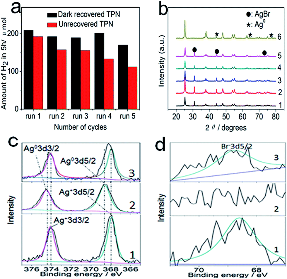 | ||
| Fig. 3 (a) Performance of 0.1 g recovered or unrecovered TPN for five consecutive photocatalytic hydrogen evolution cycles under UV-Vis light irradiation; (b) 1 to 5 are the corresponding XRD patterns of recovered TPN from run 1 to run 5 in (a), respectively; 6 represents the XRD pattern of unrecovered TPN via a photocatalytic process. (c) Ag 3d and (d) Br 3d are XPS high-resolution spectra of TPN: 1, 2, and 3 in (c) and (d) represent the corresponding valences in pristine, unrecovered, and recovered TPN, respectively. | ||
To verify the above conclusion, the first-principles density functional theory (DFT) was used to calculate the chemisorption of Br2 on TiO2 (101) surface, since the anatase nanocrystals in TPN have been proven to expose {101} faces to offer the photo-reduction sites in Fig. 1d. The calculations performed in this study were done using the CASTEP of Materials studio. Specifically, models of Br2 adsorption on a layer of atom in (2 × 2 × 1) lattice cell of TiO2 (101) facet at different sites (see Fig. 4a–e) were built to investigate the influence of Br2 adsorption on chemisorption energy (the detailed calculation is listed in Table S4†). According to the calculation, all values of chemisorption energy (ΔEchem) (see Fig. 4f) are negative, indicating Br2 adsorption on TiO2 (101) facet is able to reduce its surface energy and to pose a positive influence on photocatalytic hydrogen evolution. Herein, our strategy of promoting the performance of TiO2-based photocatalytic hydrogen evolution by building an AgBr self-recovery system to repeatedly optimize the surface energy of TiO2 is successful and effective.
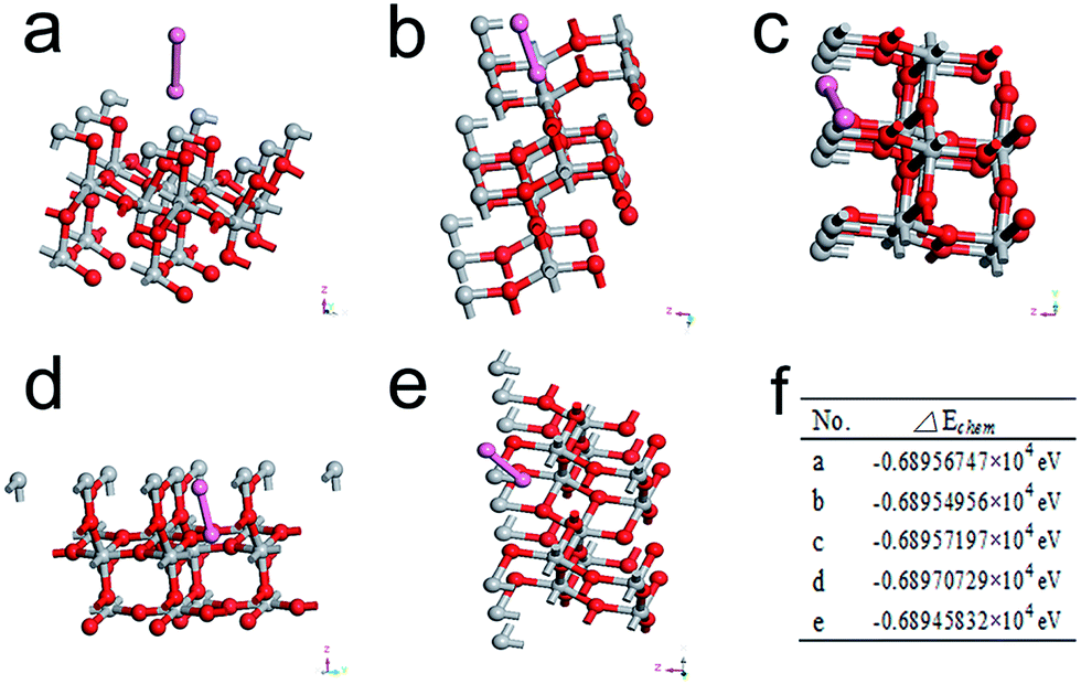 | ||
| Fig. 4 (a) to (e) are the models of one Br2 adsorbs on a layer of atom in (2 × 2 × 1) lattice cell of TiO2 (101) facet (pink, red, and gray atoms represent Br atoms, O atoms, and Ti atoms, respectively); (f) shows the ΔEchem corresponding to the modals of (a) to (e), respectively. | ||
Conclusions
In summary, we successfully explored a simple and efficient solution to build an AgBr photochromic self-recovery system in TiO2 matrix to immobilize Br2 in photocatalysts after photocatalysis. In this way, a sustained effect of reducing the TiO2 surface energy can be achieved by the repeating Br2 adsorption to achieve stable photocatalytic hydrogen evolution, since TiO2 is the final electron acceptor in TPN. This result firmly confirms the significance of our strategy in promoting the TiO2 activity by modifying its surface energy. Although TiO2-based photocatalysts have been widely studied, our results of achieving a self-recovery reaction in TiO2 matrix to maintain the stability of TiO2 opens up a new approach to boost TiO2-based photocatalytic hydrogen evolution. Besides, this self-recovery reaction may provide an inspiration to construct more efficient artificial photosynthetic systems by imitating the light and dark reactions of natural photosynthesis because natural photosynthesis also contains indispensable light and dark reactions to achieve efficient photoelectric conversion.34–37 Moreover, the method of exploring and utilizing a Ti3+ containing titanium precursor, a credible approach for multicomponent systems, can also be applied to accurately duplicate natural or artificial templates because the hydrolytic rate of the titanium precursor is uniform and stable due to crosslinking. In this way, it is possible to bring efficient natural or artificial structural units into photocatalysts to boost the efficiency of artificial photosynthesis.Acknowledgements
This work was financially supported by the National Natural Science Foundation of China (nos 51102163, 514252032 and 51171109), and the Research Fund for the Doctoral Program of Higher Education (nos 20100073110065and 20110073120036).Notes and references
- A. J. Bard and M. A. Fox, Acc. Chem. Res., 1995, 28, 141–145 CrossRef CAS.
- A. Fujishima and K. Honda, Nature, 1972, 238, 37–38 CrossRef CAS.
- J. Liu, G. L. Liu, M. Z. Li, W. Z. Shen, Z. Y. Liu, J. X. Wang, J. C. Zhao, L. Jiang and Y. L. Song, Energy Environ. Sci, 2010, 3, 1503–1506 CAS.
- W. Kim, T. Tachikawa, T. Majima, C. H. Li, H.-J. Kimc and W. Y. Choi, Energy Environ. Sci, 2010, 3, 1789–1795 CAS.
- M. D'Arienzo, J. Carbajo, A. Bahamonde, M. Crippa, S. Polizzi, R. Scotti, L. Wahba and F. Morazzoni, J. Am. Chem. Soc., 2011, 133, 17652–17661 CrossRef PubMed.
- X. B. Chen, L. Liu, P. Y. Yu and S. S. Mao, Science, 2011, 331, 746–750 CrossRef CAS PubMed.
- X. Hua, K. Wang and T. G. Xu, chemcatchem, 2014, 6, 842–847 CrossRef.
- Y.-w. Jun, M. F. Casula, J.-H. Sim, S. Y. Kim, J. Cheon and A. P. Alivisatos, J. Am. Chem. Soc., 2003, 125, 15981–15985 CrossRef CAS PubMed.
- A. Zaban, S. T. Aruna, S. Tirosh, B. A. Gregg and Y. Mastai, J. Phys. Chem. B, 2000, 104, 4130–4133 CrossRef CAS.
- H. G. Yang, C. H. Sun, S. Z. Qiao, J. Zou, G. Liu, S. C. Smith, H. M. Cheng and G. Q. Lu, Nature, 2008, 29, 638–641 CrossRef PubMed.
- W. H. Armistead and S. D. Stookey, Science, 1964, 144, 150–154 CAS.
- D. A. Nolan, N. F. Borrelli and J. W. H. Schreurs, J. Am. Ceram. Soc., 1980, 63, 305–308 CrossRef CAS PubMed.
- G. H. Li, N. M. Dimitrijevic, L. Chen, T. Rajh and K. A. Gray, J. Phys. Chem. C, 2008, 112, 19040–19044 CAS.
- N. Kakuta, N. Goto, H. Ohkita and T. Mizushima, J. Phys. Chem. B, 1999, 103, 5917–5919 CrossRef CAS.
- L. Q. Liu, S. X. Ouyang and J. H. Ye, Angew. Chem., Int. Ed., 2013, 52, 6689–6693 CrossRef CAS PubMed.
- Y. S. Xu and W. D. Zhang, Dalton Trans., 2013, 42, 1094–1101 RSC.
- Z. K. Zheng, B. B. Huang, Z. Y. Wang and Y. Dai, J. Phys. Chem. C, 2009, 113, 14448–14453 CAS.
- S. Maroie, G. Haemers and J. J. Verbist, Appl. Surf. Sci., 1984, 17, 463–476 CrossRef CAS.
- D. Barreca, G. Carraro, E. Comini, A. Gasparotto, C. Maccato, C. Sada, G. Sberveglieri and E. Tondello, J. Phys. Chem. C, 2011, 115, 10510–10517 CAS.
- M. S. Hamdy, R. Amrollahi and G. Mul, ACS Catal., 2012, 2, 2641–2647 CrossRef CAS.
- L. Ramqvist, K. Hamrin, G. Johansson, A. Fahlman and C. Nordling, J. Phys. Chem. Solids, 1969, 30, 1835–1847 CrossRef CAS.
- K. Watanabe, D. Menzel, N. Nilius and H. J. Freund, Chem. Rev., 2006, 106, 4301–4320 CrossRef CAS PubMed.
- A. Kumar, A. S. Patel and T. Mohanty, J. Phys. Chem. C, 2012, 116, 20404–20408 CAS.
- J. Jiang, H. Li and L. Z. Zhang, Chem.–Eur. J, 2012, 18, 6360–6369 CrossRef CAS PubMed.
- R. Livingston and H. Zeldes, J. Chem. Phys., 1966, 44, 1245–1259 CrossRef CAS PubMed.
- Y. Hou, X. Y. Li, Q. D. Zhao, G. H. Chen and C. L. Raston, Environ. Sci. Technol., 2012, 46, 4042–4050 CrossRef CAS PubMed.
- F. P. Koffyberg and F. A. Benko, J. Appl. Phys., 1982, 53, 1173–1177 CrossRef CAS PubMed.
- J. Ghijsen, L. H. Tjeng, J. Van Elp, H. Eskes, J. Westerink and G. A. Sawatzky, Phys. Rev. B: Condens. Matter Mater. Phys., 1988, 38, 11322–11330 CrossRef CAS.
- M. Miyauchi, A. Nakajima, T. Watanabe and K. Hashimoto, Chem. Mater., 2002, 14, 2812–2816 CrossRef CAS.
- Y. B. Wang, Y. N. Zhang, G. H. Zhao, H. Y. Tian, H. J. Shi and T. C. Zhou, ACS Appl. Mater. Interfaces, 2012, 4, 3965–3972 CAS.
- Y. Shibata, R. Hamada, T. Ueda, Y. Ichihashi, S. Nishiyama and S. Tsuruya, Ind. Eng. Chem. Res., 2005, 44, 8765–8772 CrossRef CAS.
- R. C. Wilson and R. J. Myers, J. Chem. Phys., 1976, 64, 2208–2211 CrossRef CAS PubMed.
- B. K. Meyer, A. Polity, D. Reppin, M. Becker, P. Hering, P. J. Klar, T. Sander, C. Reindl, J. Benz and M. Eickhoff, Phys. Status Solidi B, 2012, 249, 1487–1509 CrossRef CAS.
- D. Gust, T. A. Moore and A. L. Moore, Acc. Chem. Res., 2009, 42, 1890–1898 CrossRef CAS PubMed.
- D. G. Nocera, Acc. Chem. Res., 2012, 45, 767–776 CrossRef CAS PubMed.
- Y. Munekage, M. Hashimoto, C. Miyake, K. I. Tomizawa, T. Endo, M. Tasaka and T. Shikanai, Nature, 2004, 429, 579–582 CrossRef CAS PubMed.
- M. hervẚs, J. Navarro and M. A. Delarose, Acc. Chem. Res., 2003, 36, 798–805 CrossRef PubMed.
Footnote |
| † Electronic supplementary information (ESI) available. See DOI: 10.1039/c4ra15416a |
| This journal is © The Royal Society of Chemistry 2015 |