Novel photovoltaic donor 1–acceptor–donor 2–acceptor terpolymers with tunable energy levels based on a difluorinated benzothiadiazole acceptor

Zhiqiang Denga, Feiyan Wua, Lie Chen*ab and Yiwang Chenab
aCollege of Chemistry/Institute of Polymers, Nanchang University, 999 Xuefu Avenue, Nanchang 330031, China. E-mail: chenlienc@163.com; Fax: +86 791 83969561; Tel: +86 791 83968830
bJiangxi Provincial Key Laboratory of New Energy Chemistry, Nanchang University, 999 Xuefu Avenue, Nanchang 330031, China

Received 25th November 2014 , Accepted 12th January 2015

First published on 12th January 2015


Abstract

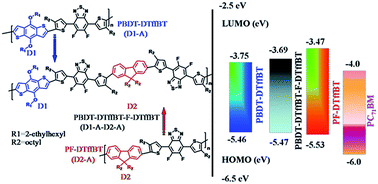
A novel donor 1–acceptor–donor 2–acceptor (D1–A–D2–A) type terpolymer PBDT-DTffBT-F-DTffBT was prepared to further tune the energy levels of donor–acceptor (D–A) type copolymer PBDT-DTffBT and PF-DTffBT, and the corresponding optoelectronic properties have been investigated. By incorporating the weak donor fluorene unit into the backbone of PBDT-DTffBT, the PBDT-DTffBT-F-DTffBT exhibits a lower HOMO level and higher LUMO level compared with PBDT-DTffBT as expected. The polymer solar cell (PSC) based on PBDT-DTffBT-F-DTffBT affords the improved PCE with a higher Voc of 0.853 V compared to the D–A copolymer PBDT-DTffBT and PF-DTffBT. Therefore, through carefully choosing the suitable donor group, the class of D1–A–D2–A type copolymers would be a promising organic semiconducting material.

Introduction

Bulk heterojunction (BHJ) polymer solar cells (PSCs) have made significant progress in terms of power conversion efficiencies (PCEs) recently.1,2 The significant increase in PCEs largely originates from the successful development of new electron donor conjugated donor–acceptor (D–A) polymers.3 The D–A design offers an important advantage of individually tuning the band gap and energy levels of the conjugated polymer. The highest occupied molecular orbital (HOMO) and lowest unoccupied molecular orbital (LUMO) levels can be adjusted by varying the electron donating ability of the donor moiety and the electron affinity of the acceptor moiety.4 In short, a suitable couple of electron acceptor and donor will obtain high efficiency in the PSCs.5 However, many of the D–A conjugated copolymers for PSC reported so far, which combine one type of donor and one type of accepter moiety in the copolymer chain, show relatively high PCE of 5–7%, but their unsuitable energy levels and band gaps constrain their further development. For example, since fluorine atoms substituted directly on the backbone of conjugated polymers have shown great promise in enhancing the efficiency of BHJ PSCs, the great potential of benzo[1,2-b:4,5-b′]dithiophene (BDT)-difluorinated benzothiadiazole (DTffBT) or benzoselenadiazole (DTffBSe) structure polymers was revealed.6–9 PSCs containing the copolymers based on BDT and DTffBT(Se) exhibit ∼5% of PCE with a high Voc of over 0.9 V.10,11 Nevertheless, as a minimum energy difference of ∼0.3 eV between the LUMO energy levels of the donor polymer and the acceptor is required to facilitate efficient exciton splitting and charge dissociation, and their low LUMO levels over −3.7 eV leads to a low Jsc of ∼9 mA cm−2.12 Similarly, the D–A copolymer with fused diketopyrrolopyrrole (DPP) unit enforces a high degree of planarity and the strong inter-chain π–π interactions can facilitate charge transport. Thus, devices use DPP containing polymers show efficiencies in excess of 5% and mobilities in excess of 1 cm2 V−1 s−1. In spite of the good device performance, the higher HOMO level over −5.2 eV of most DPP-based D–A copolymers results in a relatively low Voc of 0.6–0.7 V.13,14

Herein we present a new strategy that construct alternating donor 1–acceptor–donor 2–acceptor (D1–A–D2–A) terpolymer with two donors and one acceptor to further fine-tune energy levels and optical band gap of the D–A copolymers. In previous report, Bumjoon J. Kim et al. combines the different electron-deficient units of DPP and thieno[3,4-c]-pyrrole-4,6-dione (TPD) with thienyl-substituted benzo[1,2-b:4,5-b′]dithiophene (BDTT) to yield a series of random terpolymers. They successfully tuned the energy levels and increased the PCE from 5.0% to 6.3%.15 Compared with the random terpolymer, the regular D1–A–D2–A alternation allows the exact chemical composition. Moreover, the random incorporation of the different units often affects the molecular ordering, but regular alternation of units along the polymer chain will avoid this defect on molecular geometry. The novel terpolymer chooses BDT as electron-rich unit (D1), and the weaker donor fluorene (F) as D2, whereas difluorinated benzothiadiazole (DTffBT) is selected as the electron acceptor (A). Similar to BDT unit, fluorene is rigid planar molecules, but fluorene owns higher LUMO level and lower HOMO energy level. Thus, after replacing segmental BDT with fluorene can realize the increased LUMO level and decreased HOMO level for more efficient exciton splitting and charge dissociation, and obtaining higher Voc values.

In this work, three conjugation copolymers, poly{4,8-bis(2-ethylhexyl)-benzo[1,2-b:4,5-b′]-dithiophene-4,7-bis(4-hexylthienyl)-5,6-difluoro-2,1,3-benzothiadiazole} (PBDT-DTffBT), poly{9,9-dioctyl-fluorene-4,7-bis(4-octylthienyl)-5,6-difluoro-2,1,3-benzothiadiazole} (PF-DTffBT) and poly{4,8-bis(2-ethylhexyl)-benzo[1,2-b:4,5-b′]-dithiophene-4,7-bis(4-hexylthienyl)-5,6-difluoro-2,1,3-benzothiadiazole-9,9-dioctyl-fluorene-4,7-bis(4-hexylthienyl)-5,6-difluoro-2,1,3-benzothiadiazole} (PBDT-DTffBT-F-DTffBT) have been successfully synthesized (Scheme 1). The photophysics properties and morphology of these copolymers have been measured to study the effects of the structure of D1–A–D2–A on the molecular packing and their corresponding photovoltaic properties.


image file: c4ra15181j-s1.tif
Scheme 1 Synthetic route of monomers and copolymers.

Results and discussion

Synthesis and characterization of the monomers and copolymers

The synthetic routes and chemical structures of the monomers and copolymers are outlined in Scheme 1. PBDT-DTffBT and PBDT-DTffBT-F-DTffBT were prepared in a Stille reaction using tris(dibenzylideneacetone)dipalladium (Pd2(dba)3) catalyst and tri-o-tolylphosphine (P(o-tolyl)3) ligand, while PF-DTffBT was prepared in a Suzuki reaction using tetrakis(triphenylphosphine)palladium (Pd(PPh3)4) catalyst and potassium carbonate base. PBDT-DTffBT and PBDT-DTffBT-F-DTffBT are well soluble (∼15 mg mL−1) in common organic solvent such as chloroform, chlorobenzene, and 1,2-dichlorobenzene, whereas PF-DTffBT shows relatively poor soluble in these solvents. The structures of the monomers and their corresponding copolymers have been confirmed by 1H NMR spectra, related dates and 1H NMR pictures are presented in ESI (SI) (Fig. SI 1–10). The molecular weight (Mn and Mw) and polydispersity index (PDI) of the copolymers were obtained by performing gel permeation chromatography (GPC) relative to polystyrene standards in tetrahydrofuran at 30 °C. A much lower molecular weight is obtained for PF-DTffBT is due to its poor solubility compared to PBDT-DTffBT and PBDT-DTffBT-F-DTffBT.

Thermal properties

The thermal properties of polymers were investigated by thermogravimetry analysis (TGA) and differential scanning calorimetry (DSC). PBDT-DTffBT, PF-DTffBT and PBDT-DTffBT-F-DTffBT have good thermal stability with decomposition temperatures (5% weight loss) of 357 °C, 380 °C and 430 °C, respectively (Fig. SI 11a and Table 1). As shown in Fig. SI 11b, no clear transition can be realized by DSC analysis for PBDT-DTffBT-F-DTffBT in the heating range from 30 to 200 °C. A weak endothermic peak is detectable on heating at 131 °C, and an exothermic peak on cooling at 118 °C from curve of PBDT-DTffBT. In addition, an unapparent transition in PF-DTffBT profile at 87 °C on cooling cycle is found.
Table 1 Molecular weight and thermal properties of polymers
  Mw (kg mol−1) Mn (kg mol−1) PDI Tda (°C)
a The decomposition temperature corresponding to a 5% weight loss.
PBDT-DTffBT 35.6 15.3 2.32 357
PF-DTffBT 13.2 8.46 1.56 380
PBDT-DTffBT-F-DTffBT 37.3 14.8 2.51 430


Optical properties

The normalized optical absorption of the copolymers was studied both in chloroform solution and in thin film, with the profiles shown in Fig. 1 and the correlated parameters summarized in Table 2. The PBDT-DTffBT displays three absorption bands in the range from 300 nm to 700 nm both in solution and in solid state (film), while PF-DTffBT and PBDT-DTffBT-F-DTffBT show two ones. The absorption maximum of PBDT-DTffBT and PF-DTffBT is located at 570 nm and 498 nm respectively in solution. After incorporating BDT, DTffBT and F units into the main chain cause an in-between absorption maximum of 530 nm for PBDT-DTffBT-F-DTffBT (Fig. 1a). Similarly, absorption spectra of thin films exhibit the same variation pattern and the bands red shifted by 40 nm for PBDT-DTffBT, 14 nm for PF-DTffBT and 50 nm for PBDT-DTffBT-F-DTffBT, compared to those in solution (Fig. 1b). Moreover, a shoulder peak shows at ∼650 nm for PBDT-DTffBT, and ∼632 nm for PBDT-DTffBT-F-DTffBT, and the relative intensity is enhanced greatly from solution to film. The presence of shoulder peaks indicate a vibronic progression ascribing to an enhanced co-planarization of the conjugated system.16 The result suggesting that incorporating fluorene unit to the backbone of PBDT-DTffBT to construct the structure of D1–A–D2–A (PBDT-DTffBT-F-DTffBT) may distorts the conjugated backbone and reduces the effective conjugation length of the copolymer, due to inferior co-planarity between fluorene and conterminal segment. The corresponding optical band gaps of PBDT-DTffBT, PF-DTffBT and PBDT-DTffBT-F-DTffBT were estimated to be 1.71, 2.06, and 1.78 eV according to the absorption edge of these films. And the band gap change of PBDT-DTffBT-F-DTffBT compared with PBDT-DTffBT and PF-DTffBT implying that the variation of energy levels. Although the optical band gap of PBDT-DTffBT-F-DTffBT is larger than that of PBDT-DTffBT, but it still matches well with the solar flux.
image file: c4ra15181j-f1.tif
Fig. 1 Absorption spectra of copolymers in dilute chloroform solution (a) and as thin film (b).
Table 2 Optical and electrochemical properties of polymers
  Solution Film Eonsetox/HOMO (eV) LUMO (eV)
λmax (nm) λonset (nm) Eoptg (eV) λmax (nm) λonset (nm) Eoptg (eV)
PBDT-DTffBT 356, 445, 570 718 1.73 372, 450, 600 725 1.71 0.76/−5.46 −3.75
PF-DTffBT 360, 498 570 2.17 370, 512 602 2.06 0.83/−5.53 −3.47
PBDT-DTffBT-F-DTffBT 362, 530 686 1.81 388, 580 696 1.78 0.77/−5.47 −3.69


Electrochemical properties

Cyclic voltammetry measurements were used to HOMO energy levels by using the onset of oxidation and the voltammograms were displayed in Fig. SI 12.17 LUMO energy levels were deduced by addition of Eg to the HOMO levels. As shown in the Table 2, the calculated HOMO values are −5.46, −5.53 and −5.47 eV for PBDT-DTffBT, PF-DTffBT and PBDT-DTffBT-F-DTffBT, respectively, and the corresponding LUMO values are −3.75, −3.47 and −3.69 eV. Owing to the incorporated weak donor fluorene moiety, PBDT-DTffBT-F-DTffBT and PF-DTffBT present the lower HOMO levels than PBDT-DTffBT, which are beneficial for achieving higher Voc in their solar cell devices. More importantly, the LUMO level of PBDT-DTffBT-F-DTffBT is 0.06 eV higher than PBDT-DTffBT, indicating the more efficient charge transfer from copolymer to PC71BM. Energy level diagrams of copolymer are revealed in Fig. 2.
image file: c4ra15181j-f2.tif
Fig. 2 Energy level diagrams of polymer.

Density functional theory (DFT) computation is also performed at the B3LYP/6-31G (**) level with the Gaussian 09 package to give a deep insight into the electronic structures and the geometric of these polymers, and the molecular simulation is carried out with one repeating unit (n = 1) for representation.18 The alkyl groups are replaced by methyl groups for convenient simulation, where the electronic properties and equilibrium geometries will not be influenced significantly.19 The theoretic calculations present that the HOMO wave functions are well distributed over the donor and acceptor units while their LUMO wave functions are principally localized on the acceptor parts. The full localization of HOMO coefficients along the molecular axis is beneficial for the efficient hole transport through π-orbital interactions. For BDT-DTffBT, the energy-minimized dihedral angle (θ) between the planes of BDT and DTffBT is 27.1°, however, the θ between fluorene and DTffBT increase to 38.8° for F-DTffBT. Therefore, after bring in the fluorene to PBDT-DTffBT main chain, the backbone of PBDT-DTffBT-F-DTffBT possesses the larger θ (Fig. 3) and bigger backbone torsion, suggesting the more disordered molecular packing in the thin film. The result is well consistent with the UV observation.


image file: c4ra15181j-f3.tif
Fig. 3 The calculated HOMO and LUMO levels of BDT-DTffBT, F-DTffBT, and BDT-DTffBT-F-DTffBT models.

X-ray diffraction (XRD) analysis of the copolymer thin films was performed to investigating the molecular stacking of these polymers (Fig. 4). All the pure polymer films casted from their chlorobenzene (CB) solutions displayed two diffraction peaks in the ranges of 4.0–6.0° and 23–24°. Related to the polymer lamellar spacing, the first peak (100) revealed an decrease tendency from 5.3° for PF-DTffBT, to 4.5° for PBDT-DTffBT, and then to 4.2° for PBDT-DTffBT-F-DTffBT. Because of the difference size, type, position and orientation of side chains, PBDT-DTffBT-F-DTffBT with kinds of side chain show the longest lamellar spacing of 23.2 Å.20 The intense and sharp peak (100) observed for PBDT-DTffBT-F-DTffBT indicates that it adopts more ordered interlayer packing structure than the others. For all three polymers, the weak peak (010) at high angle, corresponding to the π–π stacking distance, are broad and without prominent difference on intensity and location, meaning that constructing the terpolymer has little effect on the polymer chain packing structure in the film of the original bipolymer. The discovery of XRD seems diverged from those of UV and DFT computation, but given that the low intensity of (010) peak, we can deduce the difference in molecular ordering of PBDT-DTffBT-F-DTffBT with PBDT-DTffBT is not serious and it is unobservable in XRD measurement.


image file: c4ra15181j-f4.tif
Fig. 4 XRD patterns of all studied copolymers.

As it was directly related to exciton dissociation, charge transport, and recombination, the hole mobility of the polymer and PC71BM blend has been measured using the space charge limited current (SCLC) method with a device configuration of glass/ITO/PEDOT:PSS/polymer:PC71BM/MoO3/Al. The mobility curves before and after adding 1,8-diiodooctane (DIO) with the volume ratio of 3% are plotted in Fig. SI 13. Without additive, the calculated mobility values of PBDT-DTffBT, PF-DTffBT, and PBDT-DTffBT-F-DTffBT are 3.5 × 10⁻⁶ cm2 V−1 s−1, 1.1 × 10⁻⁹ cm2 V−1 s−1, and 5.2 × 10⁻⁷ cm2 V−1 s−1, respectively. The higher mobility value of PBDT-DTffBT compared to PBDT-DTffBT-F-DTffBT is not surprising since UV analysis and DFT computation indicate the analogous results. After adding DIO, the mobility of PBDT-DTffBT is up to 8.5 × 10⁻⁶ cm2 V−1 s−1, and PF-DTffBT is up to 2.5 × 10⁻⁹ cm2 V−1 s−1. Note that PBDT-DTffBT-F-DTffBT has a lower mobility (1.5 × 10⁻⁷ cm2 V−1 s−1) when DIO adding, suggesting the inferior charge-transportation channel may due to the more disorder stacking of polymer:PC71BM blend and morphological factors dominate the transport characteristics.

Photovoltaic devices were prepared using a glass/ITO/PEDOT:PSS/polymer:fullerene-blend/LiF/Al device structure, measured under 100 mW cm−2 AM 1.5 illumination. The active layer blends of polymers and [6,6]-phenyl-C71-butyric acid methyl ester (PC71BM) were spin-coated from CB with each optimum composition. The current density–voltage (JV) curves are shown in Fig. 5, the optimal device parameters are summarized in Table 3, and the data of devices with other blending ratio of polymer:PC71BM are presented in Table SI 1. Initially, BHJ device utilizing PBDT-DTffBT shows the power conversion efficiency (PCE) of 2.3% with an open circuit voltage (Voc) of 0.742 V, a short-circuit current density (Jsc) of 7.71 mA cm−2, and a fill factor (FF) of 39.5%. The PCE of 2.3% is not as high as the best reported value of devices with BDT and DTffBT based D–A copolymer, mainly due to the non-optimized alkyl side chain.6–8 In contrast, device based on PBDT-DTffBT-F-DTffBT had a much larger Voc of 0.853 V as expected from its lower HOMO energy level, the similar Jsc of 7.60 mA cm−2 and FF of 37.9%, resulting in the better PCE of 2.5%. And we believe that the PCE of the terpolymer can be further improved by precisely tuning the alkyl side chain. This comparable Jsc for PBDT-DTffBT-F-DTffBT to PBDT-DTffBT is attributed to the improved efficient exciton splitting and charge dissociation caused by the higher LUMO level. Because the larger minimum energy difference between the LUMO energy levels of PBDT-DTffBT-F-DTffBT and PC71BM of ∼0.31 eV (vs. ∼0.25 eV) is beneficial for Jsc and FF.11 Notably, although PBDT-DTffBT-F-DTffBT possesses the worse light absorption and molecule co-planarity with respect to PBDT-DTffBT counterpart, but its higher PCE reveals that the effect of energy levels on efficiency is more important than light absorption and molecule co-planarity in our case. Unfortunately, take the energy difference between the LUMO energy levels of polymer and PCBM into account, the LUMO levels of −3.75 eV and −3.69 eV both are relatively low compared to the state-of-the-art D–A copolymers that limit the Jsc (∼7 mA cm−2) and FF (∼40%) in devices.21,22


image file: c4ra15181j-f5.tif
Fig. 5 Characteristic JV curves of the BHJ solar cell fabricated from these copolymers and from their respective blend with or without the DIO additive.
Table 3 Photovoltaic performance and hole mobility of polymers in standard BHJ devices with PC71BM
Polymer Polymer:PC71BM (w/w) Hole mobility (cm2 V−1 s−1) Voc (V) Jsc (mA cm−2) FF (%) PCE (%)
PBDT-DTffBT 1[thin space (1/6-em)]:[thin space (1/6-em)]1.5 3.5 × 10⁻⁶ 0.742 7.71 39.5 2.3
1[thin space (1/6-em)]:[thin space (1/6-em)]1.5 with 3% DIO 8.5 × 10⁻⁶ 0.733 7.33 55.8 3.0
PF-DTffBT 1[thin space (1/6-em)]:[thin space (1/6-em)]2 1.1 × 10⁻⁹ 0.730 1.04 25.7 0.2
1[thin space (1/6-em)]:[thin space (1/6-em)]2 with 3% DIO 2.5 × 10⁻⁹ 0.649 2.21 31.9 0.5
PBDT-DTffBT-F-DTffBT 1[thin space (1/6-em)]:[thin space (1/6-em)]1.5 5.2 × 10⁻⁷ 0.853 7.60 37.9 2.5
1[thin space (1/6-em)]:[thin space (1/6-em)]1.5 with 3% DIO 1.5 × 10⁻⁷ 0.865 7.48 39.8 2.6


DIO is commonly used as a solvent additive to optimize the morphology owing to its high boil point and good solubility for fullerene aggregates. The parameters of device with varying DIO ratio are provided in Table SI 2. When 3% (v/v) DIO adding, the PCE was improved to 3% for PBDT-DTffBT:PC71BM device resulting from the higher FF of 55.8%, may well attributed to the smoother blend film and the better phase separation of active layer. However, the PBDT-DTffBT-F-DTffBT:PC71BM-based devices almost did not show improvement, that is, morphology of the blend film can not improved by processed with DIO. It is not strange that the device using PF-DTffBT exhibits such poor PCE of 0.2–0.5%, which can be explained by the low molecular weight, and the unfavorable molecules packing and optical absorption.

Film topography

Atomic force microscopy (AFM) was applied to investigate the thin-film microstructures and morphologies of these active layers, and the size of AFM images is 5 × 5 μm. Fig. 6a, c and e shows the typical height images of polymer:PC71BM blend films, Fig. 6b, d and f are the phase image, and the 3D images are presented in Fig. SI 14. All blend films exhibit small root-mean-square (RMS) roughness of 0.53 nm for PBDT-DTffBT, 0.64 nm for PF-DTffBT, and 0.84 nm for PBDT-DTffBT-F-DTffBT, meaning the polycrystalline grains in blend films are small, which is unfavorable for efficient phase separation, and lead to the low Jsc and FF. With 3% DIO additive, the RMS values of nanomorphology increase to 2.09 nm, 2.31 nm, and 1.27 nm for PBDT-DTffBT, PF-DTffBT, and PBDT-DTffBT-F-DTffBT, respectively, and related images are exhibited in Fig. 7. Despite the lowest RMS value, the morphology of PBDT-DTffBT-F-DTffBT:PC71BM blend film with DIO additive shows the inferior film interconnectivity and larger phase separation compared with the other films. Firstly, the more unordered molecular arrangement and bigger backbone of PBDT-DTffBT-F-DTffBT is against for ordered packing of blend film and charge mobility already. Furthermore, DIO additive may lead to polymer aggregation because DIO is a poor solvent for the conjugated polymer, resulting in the worse blend morphology as well as low mobility and Jsc.23,24 Therefore, the DIO additive does not improve the PBDT-DTffBT-F-DTffBT-based device performance but lower the hole mobility. In contrast, the DIO help the PBDT-DTffBT:PC71BM blend film develop more clear and continuous nanoscale phase separation, which enables a continuous percolating path for charge transport, thus leading to an increase in the hole mobility, FF and the device efficiency.
image file: c4ra15181j-f6.tif
Fig. 6 Topography images (a, c and e) and phase images (b, d and f) by AFM of blend films of PBDT-DTffBT:PC71BM (a and b), PF-DTffBT:PC71BM (c and d), and PBDT-DTffBT-F-DTffBT:PC71BM (e and f).

image file: c4ra15181j-f7.tif
Fig. 7 Topography images (a, c and e) and phase images (b, d and f) by AFM of blend films of PBDT-DTffBT:PC71BM with 3% DIO (a and b), PDTffBT-F:PC71BM with 3% DIO (c and d), and PBBDT-DTffBT-F-DTffBT.

Conclusions

In order to further adjust the energy levels of D–A copolymer based on DTffBT and the device performance, we have developed a D1–A–D2–A copolymer PBDT-DTffBT-F-DTffBT, and the separate D–A copolymer PBDT-DTffBT and PF-DTffBT also have been prepared for comparison. The lower HOMO level and higher LUMO level were achieved for PBDT-DTffBT-F-DTffBT compared to PBDT-DTffBT, translating to higher Voc and more efficient exciton splitting and charge dissociation. Thus, device utilizing PBDT-DTffBT-F-DTffBT afford the improved PCE of 2.5%, with a higher Voc of 0.853 V, in spite of PBDT-DTffBT-F-DTffBT possessing the worse light absorption and co-planarity. Unexpectedly, the PBDT-DTffBT-based device obtained the optimum PCE of 3% when the DIO adding, ascribe to the improved nanoscale morphology. This work demonstrates a novel way to optimize the molecular structure by construct the polymer of D1–A–D2–A type, and it is effective on the regulation of energy levels and band gap. Though no great success on device performance has been gotten in the study, but through choosing the more suitable donor group to diminish the change of molecule co-planarity and light absorption, the class of D1–A–D2–A type copolymer will be promising for high performance organic semiconducting material, and further studies are under way. Moreover, the largely increased Voc of ∼0.86 V from ∼0.74 V in PBDT-DTffBT-F-DTffBT suggesting that a target design for tandem solar cells can be develop in the system of D1–A–D2–A.

Acknowledgements

This work was financially supported by the National Natural Science Foundation of China (51263016, 51473075 and 21402080). Zhiqiang Deng and Feiyan Wu contributed equally to this work.

References

  1. Z. C. He, C. M. Zhong, S. J. Su, M. Xu, H. B. Wu and Y. Cao, Nat. Photonics, 2012, 6, 591–595 Search PubMed .
  2. J. You, L. Dou, K. Yoshimura, T. Kato, K. Ohya, T. Moriarty, K. Emery, C.-C. Chen, J. Gao, G. Li and Y. Yang, Nat. Commun., 2013, 4, 1446 CrossRef PubMed .
  3. P.-L. T. Boudreault, A. Najari and M. Leclerc, Chem. Mater., 2011, 23, 456–469 CrossRef CAS .
  4. H. Zhou, L. Yang, S. Stoneking and W. You, ACS Appl. Mater. Interfaces, 2010, 2, 1377–1383 CAS .
  5. Y. f. Li, Acc. Chem. Res., 2012, 45, 723–733 CrossRef CAS PubMed .
  6. L. Dou, W. H. Chang, J. Gao, C. C. Chen, J. You and Y. Yang, Adv. Mater., 2013, 25, 825–831 CrossRef CAS PubMed .
  7. L. Lu, Z. Luo, T. Xu and L. Yu, Nano Lett., 2013, 13, 59–64 CrossRef CAS PubMed .
  8. L. Dou, C.-C. Chen, K. Yoshimura, K. Ohya, W.-H. Chang, J. Gao, Y. Liu, E. Richard and Y. Yang, Macromolecules, 2013, 46, 3384–3390 CrossRef CAS .
  9. Y. L. Jang, W. S. Kwan, R. K. Ja, H. S. Tae and K. M. Doo, Sol. Energy Mater. Sol. Cells, 2011, 95, 3377–3384 CrossRef PubMed .
  10. F. Y. Wu, D. J. Zha, L. Chen and Y. W. Chen, J. Polym. Sci., Part A: Polym. Chem., 2013, 51, 1506–1511 CrossRef CAS .
  11. J.-H. Kim, S. A. Shin, J. B. Park, C. E. Song, W. S. Shin, H. C. Yang, Y. F. Li and D.-H. Hwang, Macromolecules, 2014, 47, 1613–1622 CrossRef CAS .
  12. H. X. Zhou, L. Q. Yang and W. You, Macromolecules, 2012, 45, 607–632 CrossRef CAS .
  13. I. Meager, R. S. Ashraf, S. Rossbauer, H. Bronstein, J. E. Donaghey, J. Marshall, B. C. Schroeder, M. Heeney, T. D. Anthopoulos and I. McCulloch, Macromolecules, 2013, 46, 5961–5967 CrossRef CAS .
  14. B. Hugo, C.-F. Elisa, H. Afshin, Y. W. Soon, Z. G. Huang, S. D. Dimitrov, R. S. Ashraf, P. R. Barry, S. E. Watkins, P. S. Tuladhar, I. Meager, J. R. Durrant and I. McCulloch, Adv. Funct. Mater., 2013, 45, 5647–5654 Search PubMed .
  15. T. E. Kang, H.-H. Cho, H. J. Kim, W. H. Lee, H. B. Kang and B. J. Kim, Macromolecules, 2013, 46, 6806–6813 CrossRef CAS .
  16. Y. S. Liu, Y. Yang, C.-C. Chen, Q. Chen, L. T. Dou, Z. R. Hong, G. Li and Y. Yang, Adv. Mater., 2013, 25, 4657–4662 CrossRef CAS PubMed .
  17. C. M. Cardona, W. Li, A. E. Kaifer, D. Stockdale and G. C Bazan, Adv. Mater., 2011, 23, 2367–2371 CrossRef CAS PubMed .
  18. M. J. Frisch, G. W. Trucks, H. B. Schlegel, G. Scalmani, V. Barone, J. V. Ortiz, J. Cioslowski, D. J. Fox, et al., Gaussian 09; Revision A.01, Gaussian, Inc., Wallingford, CT, 2009 Search PubMed .
  19. Q. Peng, S. L. Lim, I. H. Wong, J. Xu and Z. K. Chen, Chem.–Eur. J., 2012, 18, 12140–12151 CrossRef CAS PubMed .
  20. C.-Y. Mei, L. Liang, F.-G. Zhao, J.-T. Wang, L.-F. Yu, Y.-X. Li and W.-S. Li, Macromolecules, 2013, 46, 7920–7931 CrossRef CAS .
  21. M. J. Zhang, X. Guo, W. Ma, S. Q. Zhang, L. J. Huo, H. Ade and J. H. Hou, Adv. Mater., 2013, 26, 2089–2095 CrossRef PubMed .
  22. S. Q. Zhang, L. Ye, W. C. Zhao, D. L. Liu, H. F. Yao and J. H. Hou, Macromolecules, 2014, 47, 4653–4659 CrossRef CAS .
  23. C. V. Hoven, X.-D. Dang, R. C. Coffin, J. Peet, T.-Q. Nguyen and G. C. Bazan, Adv. Mater., 2010, 22, E63–E66 CrossRef CAS PubMed .
  24. T.-L. Wang, A.-C. Yeh, C.-H. Yang, Y.-T. Shieh, W.-J. Chen and T.-H. Ho, Sol. Energy Mater. Sol. Cells, 2011, 95, 3295–3330 CrossRef CAS PubMed .

Footnote

Electronic supplementary information (ESI) available. See DOI: 10.1039/c4ra15181j

This journal is © The Royal Society of Chemistry 2015