 Open Access Article
Creative Commons Attribution 3.0 Unported Licence
Dielectric properties of ultraviolet cured poly(dimethyl siloxane) sub-percolative composites containing percolative amounts of multi-walled carbon nanotubes†
K.
Goswami
,
A. E.
Daugaard
and
A. L.
Skov
*
DTU, The Danish Polymer Centre, Department of Chemical and Biochemical Engineering, Kgs. Lyngby, Denmark. E-mail: al@kt.dtu.dk
First published on 15th January 2015
Abstract
In this study a new method of multi-walled carbon nanotube (MWCNT) incorporation was employed in the preparation of ultraviolet (UV) curable MWCNT-filled poly(dimethyl siloxane) (PDMS) composites. The composites were designed to contain amounts of MWCNT above the percolation threshold, without becoming conductive. Ultrasonicated and dispersed MWCNTs were co-precipitated together with an excess of short chain α,ω-vinyl terminated PDMS with a deficient amount of thiol-crosslinker and a photoinitiator (2,2-dimethoxy-2-phenylacetophenone, DMPA) into MeOH. The entire mixture was UV irradiated, resulting in a layer of hyperbranched PDMS forming around the MWCNTs. This MWCNT mixture was added to a hyperbranched long chain PDMS to provide concentrations of MWCNT of 0.33%, 0.66% and 1%, and a fully crosslinked system was obtained in a final photochemical curing. Rheology of the composites showed a moderate decrease in storage modulus (G′) across the entire frequency range in line with an increasing amount of MWCNT, thus demonstrating that the rheological percolation threshold was not reached throughout the concentration range. Dielectric spectroscopy measurements showed an increase in permittivity in line with an increasing MWCNT content as well as the desired frequency-dependent conductivity for all samples. The composites showed moderate dielectric breakdown strength of 48 V μm−1 at 0.33 wt% MWCNT, which decreased throughout the samples to 20 V μm−1 at 1 wt%. Temperature-dependent AC conductivity studies revealed that an increase in the sample temperature could explain the premature breakdown observed for those composites with higher MWCNT loading.
Introduction
The focus on material development for dielectric elastomer (DE) transducers has centred mainly on elastomer composites with improved dielectric performance, which would allow for operation at lower voltages, reduce the need for high voltage electronic components and thus reduce the overall cost of transducer devices.1,2 In addition, it is desirable for DE transducer materials to operate significantly below electrical breakdown strength, in order to ensure good long-term stability. Silicones and acrylics are common DEs and generally possess low relative permittivity when no further modifications are performed.3 Therefore, there is a need to improve the relative permittivity of DE transducer materials, in order to reduce the operating voltage or, more generally speaking, to increase the energy density of the elastomer. The most common method of improving the relative permittivity of elastomers to be used as DE transducers is by incorporating high dielectric constant fillers in an elastomer matrix.3 However, incorporating fillers usually increases the Young's modulus of the elastomer substantially, and thus the driving voltage is not reduced as initially aimed for. An increase in elastomer stiffness – depending on the application – can either be advantageous (energy generation) or disadvantageous (actuation) to the transduction properties of the DE transducers.4,5 An alternative approach of increasing the relative permittivity of the elastomer, without an undesirable increase in elastomer stiffness, can be achieved by using organic dielectric fillers in the elastomer matrix. Carpi et al.6 showed that blending poly(3-hexylthiophene), i.e. a conjugated polymer, with a commercial silicone elastomer resulted in a combination of increased dielectric constant and decreased the Young's modulus, thereby obtaining an increased electromechanical response from the silicone composite. Dielectric permittivity of vinyl terminated poly(dimethyl siloxane) (PDMS) elastomers can also be improved significantly by blending grafted dipoles in the polymer matrix, as shown by Kussmaul et al.7 Madsen et al.8,9 demonstrated the controlled approach of grafting dipole onto a crosslinker and the subsequent crosslinking of PDMS to increase relative permittivity of the silicone matrix. Similarly, Racles et al.10 chemically modified the backbone of silicone chains for condensation cure elastomers.Investigations into the addition of conducting and semi-conducting fillers in elastomer matrix have been performed as well, since the blending process is much simpler than altering the silicone matrix on the molecular scale. It has been found that adding conducting or semi-conducting fillers in very low amounts to the elastomer matrix increases the relative permittivity of the host matrix significantly.11 Ideally, when the filler content exceeds the percolation threshold, composites show conductivity, while below they are non-conductive; however, as pointed out by Stoyanov et al.,11 the percolation threshold is strongly film-dependent. This means that even for an even, uniform thickness for a given investigated film, conductivity will vary throughout transduction. This picture becomes even more complicated when some realistic film thickness variance is included. Therefore, the challenge is double-edged, namely to increase the permittivity of composites without introducing conductivity as well as eliminating the thickness dependency of the percolation threshold.
Among several conducting and semi-conducting fillers, carbon nanotubes – due to their outstanding electrical and mechanical properties12,13 – have shown promising results as fillers for DEs. However, it has been discovered that in order to improve the dielectric permittivity of the elastomer matrix, multi-walled carbon nanotubes (MWCNTs), and in general conducting particles, can only be used in very low concentrations, to avoid the formation of conductive paths in the composites, i.e. in sub-percolative amounts.
For improved dielectric properties the goal is to load the elastomer with as much filler as possible without compromising the non-conductive nature of the elastomer. Upon poor dispersion of conductive fillers in the elastomer matrix the theoretical percolation threshold may be exceeded due to formation of agglomerates which reduce the effective concentration. This affects the mechanical properties strongly as well as the electrical breakdown strength is decreased.14 On the other hand, if the conductive fillers are ideally distributed in the elastomer matrix, e.g. by surface modification of conductive fillers,15 the percolation threshold is reached at low concentrations and thus limited increase in the dielectric permittivity is obtained. Several methods have already been reported on preventing the formation of conductive paths inside elastomers containing conductive or semi-conductive fillers, such as thermoplastic encapsulation16 and elastomeric encapsulation.17 However, the encapsulation technique puts limitations on the allowable concentration of encapsulated material since in order to maintain elastomeric properties the composite can not be filled unlimitedly and the encapsulation material naturally takes up a large fraction of the volume without contributing to improved dielectric properties or elasticity. This issue is overcome by the elastomeric encapsulation.17 However, the elastomeric encapsulation technique is currently tedious and no large-scale preparation schedule exists.
Therefore a simple process for controlled heterogeneity of the elastomer is desired where the conductive fillers are distributed in high concentrations locally with an insulating matrix surrounding. The bimodal schema utilized by Bejenariu and Skov18 and Madsen et al.19 allows for this in a simple way where the reactants are pre-reacted before the final crosslinking.
The objective of the present study is to prepare PDMS composites containing MWCNT loadings above the percolation threshold, without exhibiting percolative behaviour, through the heterogeneous introduction of the MWCNTs. MWCNT-filled PDMS networks are prepared by using UV chemistry in a controlled two-step process.
Experimental section
Materials
α,ω-Vinyl-terminated PDMS (DMS-V35 and DMS-V05) with![[M with combining macron]](https://www.rsc.org/images/entities/i_char_004d_0304.gif) n = 49
n = 49![[thin space (1/6-em)]](https://www.rsc.org/images/entities/char_2009.gif) 500 g mol−1 and 800 g mol−1, respectively, were purchased from Gelest Inc., USA. DMS-V35 and DMS-V05 are hereinafter referred to as long chain and short chain PDMS, respectively. A (mercaptopropyl)methylsiloxane-dimethylsiloxane copolymer (GP 367), used as a six functional crosslinker, was obtained from Genesee Polymers Corp., USA. Hexamethyldisilazane (HMDS) treated fumed silica (SIS6962) was purchased from Fluorochem, UK. Thin multi-walled carbon nanotubes (MWCNTs) (NANOCYL™ NC7000), with an average diameter of 9.5 nm and an average length of 1.5 microns, were obtained from Nanocyl s.a., Belgium. All other chemicals used in this study were purchased from Sigma-Aldrich and used as received.
500 g mol−1 and 800 g mol−1, respectively, were purchased from Gelest Inc., USA. DMS-V35 and DMS-V05 are hereinafter referred to as long chain and short chain PDMS, respectively. A (mercaptopropyl)methylsiloxane-dimethylsiloxane copolymer (GP 367), used as a six functional crosslinker, was obtained from Genesee Polymers Corp., USA. Hexamethyldisilazane (HMDS) treated fumed silica (SIS6962) was purchased from Fluorochem, UK. Thin multi-walled carbon nanotubes (MWCNTs) (NANOCYL™ NC7000), with an average diameter of 9.5 nm and an average length of 1.5 microns, were obtained from Nanocyl s.a., Belgium. All other chemicals used in this study were purchased from Sigma-Aldrich and used as received.
Methods
MWCNT dispersion was achieved by sonication using a sonication probe (UP200S, Hielscher – Ultrasound Technology, Germany, 200 W, 24 kHz) for 10 minutes. Mixing of the components required for the network formation was done in a SpeedMixer™ (DAC 150 FVZ, Hauschild Co., Germany) at 3500 rpm. Rheological tests were performed in a strain-controlled rheometer (ARES G2) purchased from TA Instruments, USA, with 25 mm parallel plate geometry. Measurement conditions were set to a controlled strain mode of 2%, which was ensured to be within the linear viscoelastic region as determined by initial strain sweeps. Frequency sweep experiments were performed from 100 Hz to 0.001 Hz at 23 °C. Dielectric relaxation spectroscopy (DRS) was performed on a Novocontrol Broadband Dielectric Spectrometer BDS-40 (Novocontrol Technologies GmbH & Co. KG, Germany) fitted with a Novocontrol Quattro Cryosystem temperature controller at 23 °C, 50 °C, 75 °C, 100 °C, 125 °C and 150 °C and operating in the frequency range 10−1 to 106 Hz. Electrical breakdown tests were performed on an in-house-built device based on international standards (IEC 60243-1 (1998) and IEC 60243-2 (2001)). Thicknesses of films (105–150 μm) were measured through the optical microscopy of cross-sectional cuts. The films were placed in between two spherical electrodes of 20 mm radius, and the breakdown was measured at the point of contact with a stepwise increasing voltage (50–100 V per step) at a rate of 0.5–1 steps per s. Each sample was subjected to eight breakdown measurements, and the average of these values was indicated as the breakdown strength of the sample. Optical microscope images were recorded by Leica DM LB optical microscope in light transmission mode. Samples used for optical microscope imaging had thicknesses ranging from 140–150 μm.PDMS reference material
Poly((3-mercaptopropyl)methylsiloxane-co-dimethylsiloxane) (3600 g mol−1, 0.15 g, 0.042 mmol, 0.24 mmol of thiol group) was mixed with DMPA in heptane (0.5–0.6 mL, 0.036 mmol). Thereafter, 1 g of treated fumed silica and α,ω-vinyl PDMS (3 g, 49![[thin space (1/6-em)]](https://www.rsc.org/images/entities/char_2009.gif) 500 g mol−1, 0.061 mmol, 0.12 mmol of vinyl groups) were added to give an overall stoichiometry of r = 2, where r is defined as the molar ratio between thiol and vinyl. The mixture was then mixed in the SpeedMixer™ for 2 minutes and then poured into a 4 cm × 3 cm × 1 cm steel mould placed over a glass plate lined with Parafilm® M. This setup was kept in a well-ventilated place for 30 minutes and subsequently transferred to the UV chamber (λ = 365 nm, 4.5 mW cm−2) and irradiated for 20 minutes in an ambient atmosphere.
500 g mol−1, 0.061 mmol, 0.12 mmol of vinyl groups) were added to give an overall stoichiometry of r = 2, where r is defined as the molar ratio between thiol and vinyl. The mixture was then mixed in the SpeedMixer™ for 2 minutes and then poured into a 4 cm × 3 cm × 1 cm steel mould placed over a glass plate lined with Parafilm® M. This setup was kept in a well-ventilated place for 30 minutes and subsequently transferred to the UV chamber (λ = 365 nm, 4.5 mW cm−2) and irradiated for 20 minutes in an ambient atmosphere.
PDMS MWCNT reference sample
A commercially available platinum catalysed two-part addition curing PDMS (Elastosil RT625, Wacker Chemie AG, Germany) was used as a reference material containing 1 wt% unmodified MWCNTs (sample PD_1). In the reference sample MWCNT was dispersed in heptane prior to adding to the PDMS without any modification.PDMS entrapped MWCNT
Pristine MWCNTs (0.119 g) were dispersed in N-methyl pyrrolidone (NMP) (30 mL) by sonication for 15 minutes. Poly(3-mercaptopropyl)methylsiloxane-co-dimethylsiloxane (3600 g mol−1, 0.15 g, 0.042 mmol, 0.24 mmol of thiol group) and DMPA (0.0029 g, 0.012 mmol) were added to the dispersed MWCNTs. Thereafter, short chain PDMS (0.86 g, 800 g mol−1, 1.1 mmol, 2.6 mmol of vinyl groups) was added to give a stoichiometry of r ∼ 0.1 and mixed in the SpeedMixer™ for 1 minute. The whole mixture was then added drop-wise to methanol (about 500 mL) under stirring conditions. Next, the methanol mixture was irradiated by ultraviolet (UV) light (λ = 365 nm, 2 mW cm−2) for 30 minutes under stirring conditions, in order to form pre-reacted short chain PDMS in the presence of MWCNTs. The methanol mixture was then vacuum-filtered using a 0.45 μm poly(tetrafluoroethylene) (PTFE) filter. The obtained MWCNTs were then washed with ∼100 mL methanol to remove any excess NMP. Washed MWCNTs were then left to dry at room temperature for three days. Thermogravimetric analysis (TGA) was performed on the MWCNTs to determine the ratio of pre-reacted short chain PDMS and MWCNTs.Standard procedure for sub-percolative PDMS–MWCNT composites (example given for 0.33 wt% MWCNTs)
Poly((3-mercaptopropyl)methylsiloxane-co-dimethylsiloxane) (six functional crosslinker, 3600 g mol−1, 0.0069 g, 0.0019 mmol, 0.011 mmol of thiol group) was mixed with DMPA in heptane (photo initiator, 0.5–0.6 mL, 0.036 mmol). Thereafter, long chain PDMS (49![[thin space (1/6-em)]](https://www.rsc.org/images/entities/char_2009.gif) 500 g mol−1, 3 g, 0.061 mmol, 0.12 mmol of vinyl group) and 1 g of treated fumed silica (25 wt% relative to long chain) were added to give a stoichiometry of r ∼ 0.10. The whole mixture was mixed in the SpeedMixer™ for 2 minutes and subsequently transferred to the UV chamber (λ = 365 nm, 4.5 mW cm−2) and irradiated for 20 minutes in an ambient atmosphere to provide the pre-reacted long chain PDMS. In the second step, the pre-reacted long chain PDMS was mixed with the entrapped MWCNT (0.024 g) containing 0.013 g MWCNT and 0.011 g pre-reacted short chain PDMS and 1–1.5 mL heptane. Next, additional crosslinker (3600 g mol−1, 0.13 g, 0.036 mmol, 0.21 mmol of thiol group) and DMPA in heptane (0.5–0.6 mL, 0.036 mmol) were added to give an overall stoichiometry of r = 1.5. The mixture was then mixed in the SpeedMixer™ for 2 minutes and then poured into a 4 cm × 3 cm × 1 mm steel mould placed over a glass plate lined with Parafilm® M. This setup was kept in a well-ventilated place for 30 minutes and subsequently transferred to the UV chamber (λ = 365 nm, 4.5 mW cm−2) and irradiated for 60 minutes (30 minutes from each side) in an ambient atmosphere. MWCNT contents were varied to create PDMS networks with different weight percentages of MWCNT of 0.33%, 0.66% and 1%.
500 g mol−1, 3 g, 0.061 mmol, 0.12 mmol of vinyl group) and 1 g of treated fumed silica (25 wt% relative to long chain) were added to give a stoichiometry of r ∼ 0.10. The whole mixture was mixed in the SpeedMixer™ for 2 minutes and subsequently transferred to the UV chamber (λ = 365 nm, 4.5 mW cm−2) and irradiated for 20 minutes in an ambient atmosphere to provide the pre-reacted long chain PDMS. In the second step, the pre-reacted long chain PDMS was mixed with the entrapped MWCNT (0.024 g) containing 0.013 g MWCNT and 0.011 g pre-reacted short chain PDMS and 1–1.5 mL heptane. Next, additional crosslinker (3600 g mol−1, 0.13 g, 0.036 mmol, 0.21 mmol of thiol group) and DMPA in heptane (0.5–0.6 mL, 0.036 mmol) were added to give an overall stoichiometry of r = 1.5. The mixture was then mixed in the SpeedMixer™ for 2 minutes and then poured into a 4 cm × 3 cm × 1 mm steel mould placed over a glass plate lined with Parafilm® M. This setup was kept in a well-ventilated place for 30 minutes and subsequently transferred to the UV chamber (λ = 365 nm, 4.5 mW cm−2) and irradiated for 60 minutes (30 minutes from each side) in an ambient atmosphere. MWCNT contents were varied to create PDMS networks with different weight percentages of MWCNT of 0.33%, 0.66% and 1%.
Results and discussion
The aim of this work was to prepare sub-percolative PDMS composites containing a percolative amount of MWCNTs for applications such as dielectric elastomers. Recently a two-step procedure similar to the procedure for heterogeneous bimodal networks18,19 was developed for the UV-crosslinking of silicones.20 The procedure is based on pre-reacting two network components (a long and short-chain PDMS) to improve the efficiency of the crosslinking reaction. The approach was modified to include loading of the MWCNT into one of the pre-reacted components, in order to ensure good distribution in the final network, as illustrated in Scheme 1.As shown in Scheme 1 the MWCNT was initially dispersed in a good solvent and co-precipitated into MeOH together with an 800 g mol−1 short-chain PDMS and a deficient amount of crosslinker. The ratio between the crosslinker and the end-functional PDMS was set below the critical stoichiometric ratio (rc) determined from the Flory–Stockmayer equation: rc = 1/(f − 1) = 0.2, where f is the functionality of the crosslinker. In all reactions a stoichiometric ratio of 0.1 was used, which resulted in hyper-branching by UV irradiation in all cases. The pre-reacted MWCNTs were mixed thereafter with a hyperbranched long-chain PDMS, and the combined system was subsequently crosslinked under UV irradiation. By varying the ratio between the two components a range of compositions of filled composites was prepared. In a typical composition, HPD_X refers to a 25 wt% treated fumed silica-filled PDMS network with X wt% of MWCNTs.
The effect of the mixing strategy on the distribution of MWCNT clusters were investigated by optical microscopy to get an average over a large surface area as shown in Fig. 1.
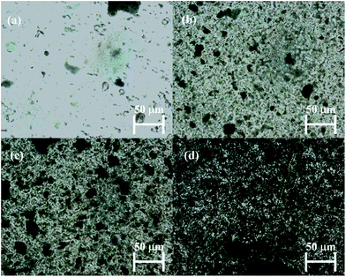 | ||
| Fig. 1 Optical microscope images of (a) HPD_0.33 (b) HPD_0.66 (c) HPD_1 and (d) reference sample PD_1. | ||
Here it is clear that the mixing strategy affects the distribution of MWCNT (Fig. 1(a–c)) to give a controlled dispersion, when comparing the samples with the reference sample PD_1 (d) containing unmodified MWCNT. The purpose of the strategy is to accommodate a larger amount of MWCNT without distributing it in the complete matrix, and thereby ensure that the ordinary percolation threshold is not met at the given MWCNT concentrations.
Rheological tests were performed on the prepared PDMS networks, with and without MWCNTs, in order to measure linear viscoelastic (LVE) properties. Fig. 2(a) shows the storage modulus (G′) and Fig. 2(b) shows the loss tangent (tan![[thin space (1/6-em)]](https://www.rsc.org/images/entities/char_2009.gif) delta) of the materials as a function of applied frequency.
delta) of the materials as a function of applied frequency.
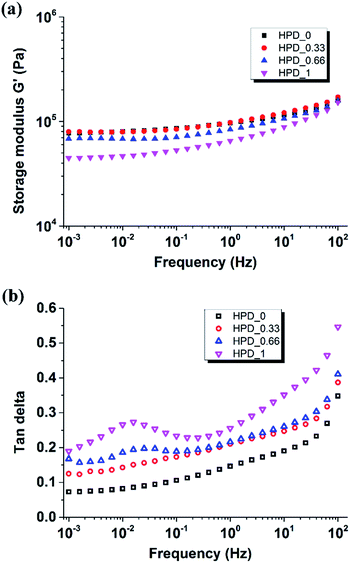 | ||
Fig. 2 (a) Storage modulus (G′) and (b) tan![[thin space (1/6-em)]](https://www.rsc.org/images/entities/char_2009.gif) delta as a function of frequency for the prepared PDMS networks at 23 °C. delta as a function of frequency for the prepared PDMS networks at 23 °C. | ||
It is evident from Fig. 2(a) that all the composites containing MWCNT exhibit a reduction in G′ compared to the non-filled network HPD_0 in the studied frequency range. The decrease in G′ can be explained by a reduction in crosslink density imposed by the presence of large aspect ratio fillers, a phenomenon also recently observed for MWCNT21 and for expanded graphite.22 In addition, the results also show little influence from the MWCNT content on G′ and thereby implying that the rheological percolation threshold is apparently not reached at the highest loading in the composites.
Damping behavior of the composites can be seen in the tan![[thin space (1/6-em)]](https://www.rsc.org/images/entities/char_2009.gif) delta plots (Fig. 2(b)), where HPD_0.33, HPD_0.66 and HPD_1 show an increase in tan
delta plots (Fig. 2(b)), where HPD_0.33, HPD_0.66 and HPD_1 show an increase in tan![[thin space (1/6-em)]](https://www.rsc.org/images/entities/char_2009.gif) delta throughout the investigated frequency range as MWCNT content increases. In addition to this, a relaxation peak appears at a frequency of ∼10−2 Hz for the MWCNT-filled PDMS composites, due to long relaxation times exhibited by the long dangling chains, which themselves are formed as a result of the destruction of the network structure around the MWCNTs.22 The observed reduction in crosslink density increases with the increase in the amount of MWCNTs in the composites, whereas no such effect is observed for HPD_0, due to the absence of the MWCNTs.
delta throughout the investigated frequency range as MWCNT content increases. In addition to this, a relaxation peak appears at a frequency of ∼10−2 Hz for the MWCNT-filled PDMS composites, due to long relaxation times exhibited by the long dangling chains, which themselves are formed as a result of the destruction of the network structure around the MWCNTs.22 The observed reduction in crosslink density increases with the increase in the amount of MWCNTs in the composites, whereas no such effect is observed for HPD_0, due to the absence of the MWCNTs.
The dielectric properties of the composites were also investigated. Fig. 3 shows the storage permittivity (ε′) and loss permittivity (ε′′) of treated fumed silica-filled PDMS networks, with and without MWCNTs, as a function of frequency at 23 °C.
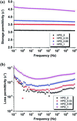 | ||
| Fig. 3 Dielectric relaxation spectroscopy data (a) storage permittivity and (b) loss permittivity as a function of frequency for PDMS composites at 23 °C. | ||
It is clear from Fig. 3(a) that the storage permittivity of the composites increases gradually in line with increasing MWCNT content, and the highest storage permittivity is obtained for HPD_1 (ε′ = 4.7 at 1 kHz), which is about 50% higher than HPD_0 (ε′ = 3.1) at 1 kHz. The trend of increasing storage permittivity with an increasing content of MWCNT content observed in this study can be explained by the boundary capacitor model.20 The MWCNTs can be considered as micro-capacitors, where the MWCNTs are separated by insulating PDMS. As the MWCNT content in the prepared composites increases, more micro-capacitors are formed, which in turn leads to higher permittivity of the composites, as observed in Fig. 4(a). Data for reference sample PD_1 can be seen in ESI.† Both storage and loss permittivity are orders of magnitude larger than the presented data and are thus omitted for clarity. The storage permittivity of PD_1 is ∼400 and dielectric losses are in the range from 3 to 106.
As seen in Fig. 3(b), increasing MWCNT content increases the dielectric loss of all the composites in the low frequency range of 0.1–10 Hz, due to dipole relaxations23 and Maxwell–Wagner polarization.24 In the medium frequency range (102 to 106 Hz), HPD_0.33 and HPD_0.66 exhibit higher losses than HPD_0, due to the motion of highly mobile conducting electrons generated from the MWCNTs.25 With the increase in MWCNT content, more closely spaced microcapacitors are formed, which favours electron flow by means of a tunneling effect and thus shows higher losses in HPD_1 (ref. 26).
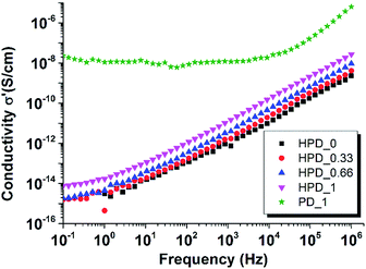
The vital requirement for DE transducers is non-conductive elastomers. Therefore, it is necessary to measure the effect of incorporating MWCNTs on AC conductivities of PDMS composites as shown in Fig. 4 for PDMS composites with varying MWCNT content measured at 23 °C.
As can be seen from Fig. 4 the AC conductivity of HPD_0 increases in line with an increase in frequency – as expected for an insulator material. Across the entire frequency range, all of the composites demonstrate frequency-dependent conductivity, which shows that the procedure effectively distributes the MWCNT throughout the system and prevents electrical percolation. There appears to be slightly higher conductivity at all frequencies for the HPD_1, though it cannot be considered conductive. It is, however, a clear indication that the gelation threshold is approached. For comparative purposes a reference PDMS elastomer, loaded with 1 wt% of MWCNT prepared under classical crosslinking conditions, was included in the plot, clearly underlining that the mixing procedure greatly affects the properties of the final composite.
High dielectric permittivity is desired for DE transducers; however, for materials to be considered for actual applications, dielectric breakdown strength also needs to be sufficiently high. Breakdown strengths of the materials were investigated and are shown in Fig. 5 as a function of MWCNT content in the PDMS composites.
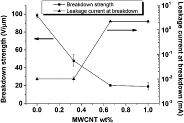 | ||
| Fig. 5 Breakdown strength variations and leakage current of PDMS composites as a function of MWCNT content. The reference sample PD_1 breaks down immediately, due to its conducting nature. | ||
From Fig. 5 it can be seen that there is a gradual reduction in breakdown strength from 100 V μm−1 in HPD_0 to 20 V μm−1 in HPD_1 and an increase in leakage current at breakdown in the composites when MWCNT content is increased. The reduction in breakdown strength can be explained by the easy flow of charges through the samples when MWCNTs in the composites are increased. In HPD_0 charges cannot flow due to the absence of MWCNTs, so a higher electric field is needed to induce electrical breakdown; consequently, the film possesses high breakdown strength compared to the other PDMS composites examined in this study. The relatively high leakage current may be avoided if the separation of domains becomes even more effective, e.g. by covalent grafting of the MWCNTs in the short chain domains. Heat generation during breakdown tests would lead to increased conductivity of polymer composites due to the semi-conductive nature of the MWCNT filler. This increase in conductivity increases sample temperature due to Joule heating, which is proportional to electrical conductivity,27 until a point is reached where the composites fail catastrophically, due to electro-thermal breakdown.28 This strong influence of temperature, and the electric field dependency of electrical conductivity on electro-thermal breakdown in PDMS films, was also reported by Zakaria et al.29
In order to investigate further the premature breakdown of MWCNT-filled PDMS composites, AC conductivities were measured at different temperatures as a function of applied frequency, as presented in Fig. 6. It highlights that the AC conductivities of all composites containing MWCNTs increase as the temperature increases from 50 °C to 150 °C. This increased conductivity is the result of the semi-conductive behaviour of the MWCNT filler. As can be seen in the figure, MWCNT content directly reflects on the onset of conductivity. HPD_0.33 (Fig. 6(a)) shows non-conductive behaviour at 50 °C, evident from frequency-dependent AC conductivity across the entire frequency range. However, when the temperature is increased to 75 °C, frequency-independent behaviour is observed at frequencies <1 Hz, thereby indicating a transition from a non-conductive to a conductive composite. At higher loadings, already at 50 °C, deviations from frequency-dependent conductivity are observed for both HPD_0.66 and HPD_1 (Fig. 6(b) and (c), respectively), which is also evident from the high leakage current flow through the material during breakdown tests. Furthermore, upon a step-wise increase in temperature from 75 °C to 150 °C, all composites (HPD_0.33, HPD_0.66 and HPD_1) show increased conductivity, indicated by an upward shift in AC conductivities at frequencies <1 Hz. During electrical breakdown tests, heat generated within the film cannot be dissipated sufficiently, which thereby leads to an increase in film temperature and then results in electro-thermal breakdown of the PDMS composites, due to the increased conductivity of the films. Moreover, as a coupled phenomenon, a local actuation of the film may happen and lead to a thinning of the film in the measurement area, therefore causing increased conductivity, as discussed by Stoyanov et al.11
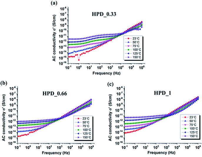 | ||
| Fig. 6 Temperature dependency of AC conductivities of (a) HPD_0.33 (b) HPD_0.66 (c) HPD_1 as a function of frequency. | ||
Conclusions
This study presents a novel method of modifying MWCNTs, which is then used to prepare PDMS composites exhibiting sub-percolative behaviour at room temperature with percolative MWCNT content. MWCNT-filled PDMS networks were obtained using UV chemistry in a controlled two-step process. Shear rheology shows a gradual reduction in G′ and an increase in tan![[thin space (1/6-em)]](https://www.rsc.org/images/entities/char_2009.gif) delta as the content of MWCNT increases, due to changes in the network structure around the MWCNTs. Storage permittivity of composites increases from 3.1 to 4.7 at 1 kHz as MWCNT content increases from 0 to 1 wt%. Non-conductive behaviour was observed at room temperature for all composites. However, following an increase in temperature, all the composites were found to become slightly conductive, due to the semi-conductive nature of the MWCNT. The composites show a decrease in dielectric breakdown strength from 100 V μm−1 to 20 V μm−1 as MWCNT content increases from 0 to 1 wt%. Due to the semi-conductive nature of the filler, these composites can lead to enhanced conductivity, which subsequently causes premature breakdown of the composites. Therefore, it can be concluded that in order to evaluate the suitability of a given elastomer, conductivity should also be investigated at elevated temperatures, due to the strong association between temperature and electrical breakdown.
delta as the content of MWCNT increases, due to changes in the network structure around the MWCNTs. Storage permittivity of composites increases from 3.1 to 4.7 at 1 kHz as MWCNT content increases from 0 to 1 wt%. Non-conductive behaviour was observed at room temperature for all composites. However, following an increase in temperature, all the composites were found to become slightly conductive, due to the semi-conductive nature of the MWCNT. The composites show a decrease in dielectric breakdown strength from 100 V μm−1 to 20 V μm−1 as MWCNT content increases from 0 to 1 wt%. Due to the semi-conductive nature of the filler, these composites can lead to enhanced conductivity, which subsequently causes premature breakdown of the composites. Therefore, it can be concluded that in order to evaluate the suitability of a given elastomer, conductivity should also be investigated at elevated temperatures, due to the strong association between temperature and electrical breakdown.
Acknowledgements
The authors would like to acknowledge financial support from InnovationsFonden.Notes and references
- Q. M. Zhang, H. Li, M. Poh, F. Xia, Z. Cheng, H. Xu and C. Huang, Nature, 2002, 419, 284–287 CrossRef CAS PubMed.
- B. Chu, X. Zhou, K. Ren, B. Neese, M. Lin, Q. Wang, F. Bauer and Q. M. Zhang, Science, 2006, 313, 334–336 CrossRef CAS PubMed.
- P. Brochu and Q. Pei, Macromol. Rapid Commun., 2010, 31, 10–36 CrossRef CAS PubMed.
- S. J. A. Koh, C. Keplinger, T. Li, S. Bauer and Z. Suo, IEEE/ASME Trans. Mechatronics, 2011, 16, 33–41 CrossRef.
- R. D. Kornbluh, R. Pelrine, H. Prahlad, A. Wong-foy, B. Mccoy, S. Kim, J. Eckerle and T. Low, in Advances in Energy Harvesting Methods, ed. N. Elvin and A. Erturk, Springer, New York, 2013, pp. 399–415 Search PubMed.
- F. Carpi, G. Gallone, F. Galantini and D. De Rossi, Adv. Funct. Mater., 2008, 18, 235–241 CrossRef CAS.
- B. Kussmaul, S. Risse, G. Kofod, R. Waché, M. Wegener, D. N. McCarthy, H. Krüger and R. Gerhard, Adv. Funct. Mater., 2011, 21, 4589–4594 CrossRef CAS.
- F. B. Madsen, L. Yu, A. E. Daugaard, S. Hvilsted and A. L. Skov, Polymer, 2014, 55, 6212–6219 CrossRef CAS PubMed.
- F. B. Madsen, A. E. Daugaard, S. Hvilsted, M. Y. Benslimane and A. L. Skov, Smart Mater. Struct., 2013, 22, 104002 CrossRef.
- C. Racles, M. Alexandru, A. Bele, V. E. Musteata, M. Cazacu and D. M. Opris, RSC Adv., 2014, 4, 37620–37628 RSC.
- H. Stoyanov, D. Mc Carthy, M. Kollosche and G. Kofod, Appl. Phys. Lett., 2009, 94, 232905 CrossRef PubMed.
- S. Iijima, Nature, 1991, 354, 56–58 CrossRef CAS.
- R. H. Baughman, A. A. Zakhidov and W. A. de Heer, Science, 2002, 297, 787–792 CrossRef CAS PubMed.
- S. Vudayagiri, S. Zakaria, L. Yu, S. S. Hassouneh, M. Benslimane and A. L. Skov, Smart Mater. Struct., 2014, 23, 105017 CrossRef.
- P. C. Ma, J. K. Kim and Z. Ben, Carbon, 2006, 44, 3232–3238 CrossRef CAS PubMed.
- M. Molberg, D. Crespy, P. Rupper, F. Nüesch, J.-A. E. Månson, C. Löwe and D. M. Opris, Adv. Funct. Mater., 2010, 20, 3280–3291 CrossRef CAS.
- P. Mazurek, S. Hvilsted and A. L. Skov, in Proceedings of SPIE, ed. Y. Bar-Cohen, 2014, vol. 9056, pp. 90562T Search PubMed.
- A. G. Bejenariu, L. Yu and A. L. Skov, Soft Matter, 2012, 8, 3917–3923 RSC.
- F. B. Madsen, A. Daugaard, C. Fleury, S. Hvilsted and A. L. Skov, RSC Adv., 2014, 4, 6939–6945 RSC.
- K. Goswami, A. L. Skov and A. E. Daugaard, Chem.–Eur. J., 2014, 20, 9230–9233 CrossRef CAS PubMed.
- Z. Li, K. Moon, Z. Lin, Y. Yao, S. Wilkins and C. P. Wong, J. Appl. Polym. Sci., 2014, 131, 40355 Search PubMed.
- S. S. Hassouneh, A. E. Daugaard and A. L. Skov, Macromol. Mater. Eng. Search PubMed in press..
- J. Zhang, M. Mine, D. Zhu and M. Matsuo, Carbon, 2009, 47, 1311–1320 CrossRef CAS PubMed.
- N. K. Shrivastava, P. Kar, S. Maiti and B. B. Khatua, Polym. Int., 2012, 61, 1683–1692 CrossRef CAS.
- C. Xiang, Y. Pan, X. Liu, X. Sun, X. Shi and J. Guo, Appl. Phys. Lett., 2005, 87, 123103 CrossRef PubMed.
- F. Nanni and M. Valentini, Polymer–Carbon Nanotube Composites, Woodhead Publishing Limited, Cambridge, United Kingdom, 2011 Search PubMed.
- M. Ieda, IEEE Trans. Electr. Insul., 1980, EI-15, 206–224 CrossRef CAS.
- X. Zhou, X. Zhao, Z. Suo, C. Zou, J. Runt, S. Liu, S. Zhang and Q. M. Zhang, Appl. Phys. Lett., 2009, 94, 162901 CrossRef PubMed.
- S. Zakaria, P. H. F. Morshuis, M. Y. Benslimane, K. V. Gernaey and A. L. Skov, in Proceedings of SPIE, ed. Y. Bar-Cohen, 2014, vol. 9056, pp. 90562V Search PubMed.
Footnote |
| † Electronic supplementary information (ESI) available. See DOI: 10.1039/c4ra14637a |
| This journal is © The Royal Society of Chemistry 2015 |


