Effect of precursor concentration on the properties and tuning of conductivity between p-type and n-type Cu1−XCdXS2 thin films deposited by a single step solution process as a novel material for photovoltaic applications

V. Nirmal Kumarab, R. Suryakarthicka, S. Karuppusamya, Mukul Guptac, Y. Hayakawab and R. Gopalakrishnan*a
aCrystal Research Lab, Department of Physics, Anna University, Chennai, India. E-mail: krgkrishnan@annauniv.edu; krgkrishanan@yahoo.com; Tel: +91-044-2235-8710
bResearch Institute of Electronics, Graduate School of Science and Technology, Shizuoka University, Hamamatsu, Japan
cUGC-DAE Consortium for Scientific Research, Indore, India

Received 26th October 2014 , Accepted 24th February 2015

First published on 24th February 2015


Abstract

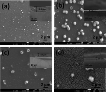
Cu1−XCdXS2 thin films were deposited from precursor solutions having different concentrations of cation sources, by a single step solution process at room temperature. The colours of the deposited films changed from light to dark brown based on the incorporation of copper and cadmium ions from the precursors. Cu1−XCdXS2 polycrystalline thin films exhibit a hexagonal structure. Cd rich films showed a sheet like morphology and poor adhesiveness owing to a cluster growth process. Wider absorption in the region 300–1300 nm was observed with a red shift in the absorption edge as the composition of Cd increased. A relative increase in the Cd composition of deposited Cu1−XCdXS2 thin films was observed as the precursor concentration of Cd increased. XPS and Raman spectra confirmed the formation of a CuCdS2 compound. Electrical properties showed the decrease in carrier concentration as Cd composition increases. The Cu1−XCdXS2 thin films exhibited both p and n-type conductivity owing to different stoichiometric ratios of cations. The analyses revealed that the Cu1−XCdXS2 thin film can be used as both a novel absorber and window layer for the fabrication of low cost thin film solar cells.


1. Introduction

Semiconductor materials with significant physical properties have been playing a major role for various technological applications. Ternary and quaternary compound/alloy semiconductors, having tuneable physical properties depending on their composition of constituent elements, play vital roles in electronic, optoelectronic, photovoltaic and thermo photovoltaic applications.1 Metal chalcogenides play a promising role in energy conversion and storage devices owing to their unique physical and chemical properties.2 Apart from III–V compound semiconductors and their alloys, chalcogenide semiconductors based on group VI elements like S and Se, have been investigated by many research groups because of their ease of synthesis and interesting properties.3,4 Besides band gap engineering by size reduction in nanomaterials, alloying them by varying the composition of constituent elements results in distinct tuneable properties favourable for a wide range of applications.5 Various ternary and quaternary semiconductor materials have been studied for their variation in properties owing to compositional change.6–9 CuCdS2, a I–II–VI2 compound, is a new material in the chalcogenide group of semiconductors and its physical properties are yet to be revealed. It has tuneable properties between those of its binary counterparts CuXS and CdS. Since copper sulphide exists in five different stable phases at room temperature, it is difficult to differentiate the formation of a particular phase CuXS.10 Similarity between the structures of CuXS and CdS binary phases was explained in a report by Cook et al., which showed the conversion of CdS single crystal into CuXS by dipping it in CuCl solution.11 Diffusion coefficient of copper in hexagonal-CdS single crystals in perpendicular and parallel direction to c-axis was measured using radio-active tracer technique and reported by Clarke.12 Moreover, p-type conductivity of CdS doped with copper was enumerated by Kashiwaba et al. and they fabricated solar cell using Cu-doped CdS as absorber layer that recorded 8.5% efficiency.13,14 Recently, Cu doped CdS nano powders were synthesized by mechanochemical route and their structural and optical properties were reported.15 So far, a detailed report on Cu1−XCdXS2 ternary compound semiconductor is not available yet. The method, which we adapted for the deposition of Cu1−XCdXS2 thin film is chemical bath deposition process that is identified as simple, convenient process for large area of deposition and yielding good quality of thin films.16 As the continuation of our previous work that explains the deposition and properties of CuCdS2 thin films, we now report the effect of precursor concentration on the deposited CuCdS2 thin films and their variation in physical properties.17

Cu1−XCdXS2 thin films were deposited from precursor solution having various compositions of cation sources by chemical bath deposition method and their physical properties were analysed by X-ray diffraction (XRD), scanning electron microscopy (SEM), electron probe micro analysis (EPMA), X-ray photo electron spectroscopy (XPS), UV-Vis, Raman spectroscopy and Hall effect measurement studies. The suitability of this material as a novel absorber and window layer for the fabrication of thin film solar cells at low cost is analysed.

2. Experiment

2.1 Deposition of CuCdS2 thin films

Thin films of CuCdS2 were prepared with various compositions by chemical bath deposition in single step at room temperature. The schematic of simple chemical bath deposition process is shown in Fig. 1. The precursor solutions for the deposition of CuCdS2 were prepared by dissolving various ratios of CuSO4·5H2O, CdSO4·8H2O and CS(NH2)2 (thiourea) as cation (Cu2+, Cd2+) and anion (S2−) sources. The concentration of anion is fixed for all reactions and only the cationic concentration (Cu2+ and Cd2+) was varied. The concentration of cations and anion sources in precursor solution used for the deposition of Cu1−XCdXS2 samples naming A to D, are shown in Table 1. All the samples were prepared simultaneously in different beakers under same conditions at room temperature.
image file: c4ra12565g-f1.tif
Fig. 1 Schematic of simple chemical bath deposition process.
Table 1 Precursor concentrations of cations and anions for the deposition of Cu1−XCdXS2 thin films
S. no. Sample Concentration (M L−1) Solution volume (mL)
CuSO4·5H2O CdSO4·8H2O CS(NH2)2
1. A 0.08 0.02 0.2 100
2. B 0.06 0.04 0.2
3. C 0.04 0.06 0.2
4. D 0.02 0.08 0.2


Required amount of CuSO4·5H2O, CdSO4·8H2O and CS(NH2)2 were dissolved in 100 mL of deionized water and ammonia was added drop by drop until pH of the solution reaches 10.5. While adding ammonia, ultrasonically cleaned glass substrate was immersed vertically in the solution. Addition of ammonia formed complex cation with copper and cadmium ions thereby slow and uniform deposition of the compound made possible owing to slow release of copper and cadmium ions. Compound formation was ensured from the change in colour of the solution from dark/light blue to dark/light brown.

Cu2+ and Cd2+ ions in the prepared solution from dissolved CuSO4 and CdSO4 were reacted with ammonia to form their complexes tetramine copper ([Cu(NH3)4]2+) and tetramine cadmium ([Cd(NH3)4]2+) cations.18,19 The formation of complex cation from precursor solution is necessary for controlled growth rate. The growth of thin film from a solution depends on their solubility constant (Ksp). As the Ksp is low for CdS than CuXS, the possibility for the formation of CdS is more when deposited as binary phase. Since the present study involves the deposition of ternary compound (Cu(1−X)CdXS2), the process depends on the formation of cations ([Cu(NH3)4]2+, [Cd(NH3)4]2+) and anion (S2−) and reaction between them.

The reactions involved in the formation of CuCdS2 is as follows,17

 
CuSO4 + CdSO4 + 8NH3 → [Cu(NH3)4]2+ + [Cd(NH3)4]2+ + 2SO42− (1)

Hydrolysis of thiourea took place to release sulphur ions as follows,

 
CS(NH2)2 + OH → CH2N2 + H2O + HS (2)
 
HS + OH → S2− + H2O (3)

([Cu(NH3)4]2+, [Cd(NH3)4]2+) and anions (S2−) reacted and formed the ternary compound CuCdS2 in the solution as follows,

 
[Cu(NH3)4]2+ + [Cd(NH3)4]2+ + 2S2− → CuCdS2 + 8NH3 (4)

The heterogeneous nucleation occurs along with homogeneous nucleation in the solution and Cu1−XCdXS2 thin films were formed on glass substrate. After 40 minutes the deposited films were taken out, rinsed and cleaned ultrasonically to remove loosely adhered particles. Under ultrasonification samples A–C were not peeled from substrate which revealed well adhesiveness of Cu1−XCdXS2 thin films whereas sample D was peeled after some time from substrate that showed comparatively poor adhesiveness. The Cu1−XCdXS2 films were dried in oven at 50 °C and subjected for further characterization.

2.2 Characterization of CuCdS2 thin films

The deposited CuCdS2 films were subjected to XRD, SEM, EPMA, XPS, UV-Vis, Raman and Hall effect measurement studies to analyse their physical properties. XRD pattern of the deposited thin films was recorded with CuKα radiation by Bruker D8 advance XRD system. Elemental analysis and surface morphology studies were performed by JEOL-JXA 8530F field emission electron probe micro analyser. Optical absorbance in the range 300–1300 nm was recorded by Perkin Elmer Lambda 950 system with uncoated glass slides as reference. Raman spectra of the deposited thin films in the range 100–1600 cm−1 were recorded by Jobin Yvon Horiba LABRAM-HR visible system. Ar ion laser having excitation wavelength 488 nm, with spot size 1 μm, was used for recording the Raman spectrum. The spectra were recorded at room temperature by CCD camera having 600 lines per mm gratings with spectral resolution of about 1 cm−1. Hall effect measurement was made using Ecopia Hall effect measurement system (HMS-3000) to analyse the electrical properties of the deposited thin films.

3. Results and discussion

3.1 Structural properties

The recorded XRD pattern of deposited thin film as shown in Fig. 2 was indexed using Crysfire software. All the deposited films exhibit poly crystalline nature with hexagonal structure. Among the four thin films, sample B (3[thin space (1/6-em)]:[thin space (1/6-em)]2) and sample C (2[thin space (1/6-em)]:[thin space (1/6-em)]3) were consist of nearly equal composition of Cu2+ and Cd2+ ions that showed nearly similar pattern in XRD. They commonly have the primary peak at 2θ value 31.9°, that corresponds to (103) plane. Samples A (Cu rich) and D (Cd rich) have primary peaks at 38.3° and 31.7°, owing to respective (103) and (102) planes. The observed shift in the primary peaks of each sample was due to the change in lattice parameter values. The lattice parameters of Cu(1−X)CdXS2 thin films having different compositions were calculated. The change in lattice parameter value upon varying the cation composition is shown in Table 2. From the table it has been found that the unit cell volume and c/a ratio both were increased upon increasing the Cd composition. These results had shown that the composition variation in deposited thin films significantly varied the structural parameters of Cu1−XCdXS2 compound. All the four Cu1−XCdXS2 thin films had hexagonal structure which was in consistent with our earlier work on analysis of CuCdS2 thin film.17
image file: c4ra12565g-f2.tif
Fig. 2 XRD patterns of Cu1−XCdXS2 thin film samples A–D.
Table 2 Observed lattice parameters of Cu1−XCdXS2 thin films
Sample Lattice parameter (Å) c/a ratio Unit cell volume (Å3)
a c
A 3.247 12.944 3.86 117.125
B 3.522 13.606 4.05 146.182
C 3.281 13.317 4.13 124.192
D 3.529 14.584 3.86 157.329


3.2 Morphological and elemental analysis

Surface morphologies of CuCdS2 thin films analysed by SEM are shown in Fig. 3(a)–(d) that revealed the formation of continuous, pin hole free coating of deposited material and particles aggregation were changed from spherical to sheet like morphology upon increasing cadmium content in the deposited films. The solubility constant (Ksp) is greater for CuXS (35.1) than CdS (15.9). Since the solubility constant is low for CdS, aggregations of particles were formed as Cd composition increased. The sheet like morphology in Cd rich film revealed the cluster growth process that resulted in poor adhesiveness of sample D, whereas ion-by-ion process revealed by SEM micrographs of samples A–C resulted in better adhesiveness of samples with substrate. The thicknesses of Cu(1−X)CdXS2 thin films were measured by taking cross-sectional SEM images which were shown as inset in Fig. 3. The thicknesses of thin film were in the range 8.5 to 38 μm.
image file: c4ra12565g-f3.tif
Fig. 3 SEM images of Cu1−XCdXS2 thin film samples A–D with cross-sectional images as inset, for thickness measurement.

Compositions of deposited material measured by EPMA are shown in Table 3. It showed that the composition of cadmium increases from samples A to D owing to relative precursor concentrations. Cd and S compositions in deposited CuCdS2 thin films were calculated and plotted as shown in Fig. 4. It revealed that the sulphur composition was almost same and the cation composition only varied in all deposited CuCdS2 thin film.

Table 3 Composition of Cu1−XCdXS2 thin films measured by EPMA
S. no. Sample Elemental compositions in CuCdS2 thin films Cd composition [Cd/(Cu + Cd)] (%)
Cu Cd S
1 A 62.90 0.34 36.76 0.5
2 B 55.07 11.80 33.13 17.7
3 C 48.38 17.56 34.06 26.6
4 D 7.53 63.38 29.09 89.4


image file: c4ra12565g-f4.tif
Fig. 4 Cd and S composition in deposited Cu1−XCdXS2 thin films measured by EPMA.

XPS spectra of CuCdS2 thin films showing Cu 2p, Cd 3d and S 2p levels are presented in Fig. 5(a)–(c) and the obtained binding energy values are given in Table 4. It is inferred from the table that the binding energy values have shift from reported binary phases CuS, Cu2S and CdS.20,21 The shift in binding energies between binary and ternary phases resulted from interaction between cations of different groups (Cu and Cd). Increase in binding energy of Cu 2p level ranging between 933.9–935.6 eV was observed as the composition of Cu decreases from sample A to D. The binding energy initially decreased from 409.31 to 407.02 eV in Cd 3d level and increased gradually as the composition of cadmium increases from sample B to D. The decrease in intensity of Cd 3d and Cu 2p levels was observed in Cu rich (sample A) and Cd rich (sample D) thin films. Even though the concentration of sulphur source in all reactions and sulphur composition was almost same in deposited thin films, binding energy of S 2p increases from 162.6 to 164 eV in samples A–D. The band structure of CdS is altered by Cu ions by the formation of space charge region (band bending). Since Cu ions act as acceptor centre, higher concentration of Cu ion in CdS altered its conductivity from n-type to p-type that resulted in p-type conductivity of Cu rich sample (sample A) in our present study.


image file: c4ra12565g-f5.tif
Fig. 5 XPS spectra of Cu1−XCdXS2 thin films showing binding energies of (a) Cu 2p (b) Cd 3d and (c) S 2p levels.
Table 4 Binding energies of Cu 2p, Cd 3d and S 2p levels of Cu1−XCdXS2 thin films measured by XPS
S. no. Sample Binding energies (eV)
Cu 2p Cd 3d S 2p
3/2 1/2 5/2 3/2
1. A 933.9 953.7 409.31 162.6
2. B 934.6 954.5 407.02 413.91 163.3
3. C 934.7 954.5 407.23 414.01 163.5
4. D 935.6 954.7 407.28 414.07 164


The shift in binding energies of Cu 2p and Cd 3d levels were attributed to band bending of both CdS and CuXS binary phases. However the band bending of CuXS is more when compared to CdS. Moreover the band alignment of Cu2S/CdS system showed that the conduction band minimum of both systems is nearly equal. Hence the energy loss due to charge transport from Cu2S to CdS is much less and this system is suitable for charge injection and carrier transport.22

3.3 Optical properties

3.3.1 UV-Vis spectral analysis. The optical response of deposited materials were recorded and absorption coefficient was calculated using the formula a = 2.303A/t, where t is the film thickness. The calculated absorption co-efficient was plotted as a function of wavelength and it was shown in Fig. 6(a) that revealed the material has wide range of absorption in 300–1300 nm region which is favourable for photovoltaic applications since maximum number of photons in solar spectrum approaching earth having wavelength in visible and near-IR regions. From the plot it was observed the absorption coefficient decreased as the Cd composition increased. A blue shift of absorption edge was observed in the spectra as the composition of Cd increased. The composition change caused the change in band gap in the range 1.46 to 1.85 eV. Band gap of deposited material was found using Tauc's plot as shown in Fig. 6(b), which were increased, ranging 1.46–1.85 eV as the composition of cadmium increases.
image file: c4ra12565g-f6.tif
Fig. 6 (a) Absorption co-efficient vs. wavelength plot and (b) Tauc's plot of Cu1−XCdXS2 thin films.

A thin film solar cell is made of p and n type semiconductor materials are kept in contact. The band gap of those materials play key role in energy conversion. Under illumination of light, the charge carriers of p-type absorber layer can absorb photons of energy equal or higher to its band gap. On the other hand, the n-type semiconductor material should have higher band gap than absorber layer so that it can transmit photons of energy below its band gap. Hence the p and n-type semiconductors should have optimum band gap so as to utilize more number of photons in solar spectrum. The optimum band gap for the potential utilization of solar spectrum is between 1–1.5 eV as maximum number of photons in sunlight approaching earth atmosphere lies in the range. Moreover the band gap of p and n-type layers should not have much variation between them. The voltage developed during absorption process should be high enough to drive charge carriers before recombination occurs. Considering these factors, the difference between band gap energies of p and n-type layers should be less than 1 eV. In our present study, the band gap of Cu rich Cu(1−X)CdXS2 (sample A) is 1.46 eV and Cd rich Cu(1−X)CdXS2 (sample D) is 1.85 eV. The variation between them is 0.39 eV. By considering the above said factors the deposited Cu(1−X)CdXS2 can potentially be utilized for the fabrication of solar cells.

The variation in band gap of Cu1−XCdXS2 thin films is plotted as a function of Cd composition as shown in Fig. 7. The increase in band gap is observed from the graph as the composition of Cd increased, whereas decrease in band gap was observed with Cu rich, ternary and quaternary compounds owing to p–d hybridization between Cu-d levels and Se p-levels, but in the present case S p-levels.23,24


image file: c4ra12565g-f7.tif
Fig. 7 Variation in band gap of Cu1−XCdXS2 thin films as a function of Cd composition.
3.3.2 Raman analysis. The vibration modes of binding state existing between Cu, Cd and S atoms were recorded by Raman spectrum (Fig. 8). Three peaks were observed at 298.9, 473.3 and 601.8 cm−1. The peaks at 298.9 and 601.8 cm−1 were attributed to 1LO and 2LO processes of CdS which nearly match with reported values. The peak at 473.3 cm−1 was resulted from S–S stretching mode of A1g symmetry assigned to CuS.25 However, shift was observed in Raman peaks for CuXS (472 and 474 cm−1) and CdS (305, 600 and 904 cm−1) binary phases.26,27 The large shift in Raman peaks may be attributed to stress developed in the material.28 The stress developed in the deposited CuCdS2 thin films is due to lattice strain between CuXS and CdS binary phases formed during the deposition process.
image file: c4ra12565g-f8.tif
Fig. 8 Raman spectra of Cu1−XCdXS2 thin films.

3.4 Electrical properties

Electrical properties of deposited Cu1−XCdXS2 thin films were studied by Hall effect measurement system and the data obtained are shown in Table 4. From the data it is observed that the carrier concentration decreases as Cd composition increases (sample A to D). Cu rich films (sample A) have shown higher carrier concentration with lower resistivity and higher mobility. The conductivity changed from p-type to n-type as the composition of Cd increases. Sample A showed p-type conductivity whereas, the other samples B–D showed n-type conductivity. The concentrations of sulphur source in precursor solution and anion composition in deposited Cu1−XCdXS2 thin films were found to be same for all the compositions. Hence the variation in stoichiometry of Cu and Cd determines the type of carriers which is in agreement with earlier report.23 A high concentration of p-type carriers in heavily Cu doped CdS is observed owing to copper 3d levels.29 P-type conductivity in Cu rich film was resulted from Cu ions acts as acceptor centers.30 Cu1−XCdXS2 thin films exhibit both p-type and n-type conductivity owing to stoichiometry of cation compositions (Table 5).
Table 5 Electrical properties of deposited Cu1−XCdXS2 thin films
S. no. Sample Carrier concentration (cm−3) Resistivity (Ω cm) Mobility (cm2 V−1 s−1) Type of charge carriers
1 A 3.48 × 10¹⁸ 0.16 10.6 p-type
2 B 1.57 × 10¹⁴ 2.41 × 10⁴ 1.64 n-type
3 C 4.07 × 10¹³ 5.66 × 10⁴ 2.7 n-type
4 D 1.8 × 10¹² 3.5 × 10⁵ 15.06 n-type


The p-type Cu(1−X)CdXS2 (sample A) has higher carrier concentration of the order of 1018 and has lower resistivity. During absorption process the generated charge carries at the pn-junction can transport through absorber that has lower resistivity driven by developed high potential in pn-junction as the difference between the band gap is as low as 0.39 eV. Though the n-type Cu(1−X)CdXS2 (sample D) shown one order of higher magnitude in resistivity than p-type Cu(1−X)CdXS2 (sample A), its mobility is high enough to transport charge carriers though it. The optimum band gap and suitable electrical properties of Cu(1−X)CdXS2 thin films can be helpful for making efficient photovoltaic device.

4. Conclusion

Cu1−XCdXS2 thin films with different compositions were deposited on glass substrates from precursor solution that had various concentrations of cation and anion sources. XRD analysis revealed the hexagonal structure of deposited films and change of lattice parameters upon varying the composition. SEM image showed continuous coating of thin films with morphology changed from spherical to sheet like structure owing to cluster growth process of Cd rich films. EPMA measurement showed the composition of S remains same and cation compositions change. Relative variations in the Cd composition of deposited films were observed as the precursor concentration varies. Increase in binding energies of Cu 2p, Cd 3d and S 2p levels were observed as the composition of cadmium increases owing to shift in valance band structure from CuXS to CdS. The deposited material has wider absorption in 300–1300 nm range and there is red shift in absorption edge as the Cd composition increased. Band gap of Cu1−XCdXS2 thin film increases from 1.46 eV to 1.85 eV for Cu to Cd rich composition. Raman peaks were observed at 298.9, 601.8 and 473.3 cm−1 owing to vibration modes of its binary phases CdS and CuXS, respectively. Carrier concentration of CuCdS2 thin films decreases as the composition of Cd increased in deposited thin films. The same material, CuCdS2 thin films exhibited two different type conductivities, p and n-type owing to composition of cations. Cu rich film showed p-type conductivity, whereas Cd rich samples showed n-type conductivity. Physical properties of Cu1−XCdXS2 thin films can be tuned between CuXS and CdS to get desired properties. Since Cu1−XCdXS2 thin films with Cu and Cd rich compositions had wider absorption region, p and n-type conductivities, higher carrier concentration and tuneable band gap between Cu2S and CdS, this material is suitable for photovoltaic applications and the same material (Cu1−XCdXS2) can perform the role of both p-type and n-type semiconductor based on their composition.

References

  1. S. Adachi, Properties of Semiconductor Alloys: Group IV, III–V, II–VI Semiconductors, Wiley, 2009, pp. 1–400 Search PubMed.
  2. M. R. Gao, Y. F. Xu, J. Jiang and S. H. Yu, Chem. Soc. Rev., 2013, 42, 2986 RSC.
  3. X. Liu, Z. Liu, F. Meng and M. Sugiyama, Sol. Energy Mater. Sol. Cells, 2014, 124, 227–231 CrossRef CAS PubMed.
  4. P. Chen, M. Qin, H. Chen, C. Yang, Y. Wang and F. Huang, Phys. Status Solidi A, 2013, 210(6), 1098 CrossRef CAS.
  5. M. D. Regulacio and M. Y. Han, Acc. Chem. Res., 2010, 43, 621 CrossRef CAS PubMed.
  6. F. D. Benedetto, I. Bencista, S. Caporali, S. Cinotti, A. D. Luca, A. Lavacchi, F. Vizza, M. M. Miranda, M. L. Foresti and M. Innocenti, Progress in Photovoltaics: Research and Applications, 2014, 22, 97 CrossRef.
  7. S. Theodoropoulou, D. Papadimitriou, K. Anestou, C. Cobet and N. Esser, Semicond. Sci. Technol., 2009, 24, 015014 CrossRef.
  8. Z. Aissa, M. Amlouk, T. Ben Nasrallah, J. C. Bernede and S. Belgacem, Sol. Energy Mater. Sol. Cells, 2007, 91, 489 CrossRef CAS PubMed.
  9. D. B. Khadka and J. H. Kim, J. Phys. Chem. C, 2014, 118, 14227 CAS.
  10. S. Y. Wang, W. Wang and Z. H. Lu, Mater. Sci. Eng., B, 2003, 103, 184 CrossRef.
  11. W. R. Cook, L. Shiozawa and F. Augustine, J. Appl. Phys., 1970, 41, 3058 CrossRef CAS PubMed.
  12. R. L. Clarke, J. Appl. Phys., 1959, 30, 957 CrossRef CAS PubMed.
  13. Y. Kashiwaba, I. Kanno and T. Ikeda, Jpn. J. Appl. Phys., Part 1, 1992, 31, 1170 CrossRef CAS.
  14. Y. Kashiwaba, K. Isojima and K. Ohta, Sol. Energy Mater. Sol. Cells, 2003, 75, 253 CrossRef CAS.
  15. P. Reyes and S. Velumani, Mater. Sci. Eng., B, 2012, 177, 1452 CrossRef CAS PubMed.
  16. R. S. Mane and C. D. Lokhande, Mater. Chem. Phys., 2000, 65, 1 CrossRef CAS.
  17. V. Nirmal Kumar, R. Suriakarthick, Y. Hayakawa, S. Hussain, G. M. Bhalerao, M. Gupta, V. Sathe and R. Gopalakrishnan, Superlattices Microstruct., 2014, 76, 125 CrossRef CAS PubMed.
  18. M. T. S. Nair and P. K. Nair, Semicond. Sci. Technol., 1989, 4, 191 CrossRef CAS.
  19. N. R. Pavaskar, C. A. Menezes and A. P. B. Sinha, J. Electrochem. Soc., 1977, 124, 743 CrossRef CAS PubMed.
  20. Y. B. He, A. Polity, I. Osterreicher, D. Pfisterer, R. Gregor, B. K. Meyer and M. Hardt, Phys. B, 2001, 308–310, 1069 CrossRef CAS.
  21. D. M. Poirier and J. H. Weaver, Surf. Sci. Spectra, 1993, 2, 249 CrossRef CAS.
  22. G. Liu, T. Schulmeyer, J. Brotz, A. Klein and W. Jaegermann, Thin Solid Films, 2003, 431–432, 477 CrossRef CAS.
  23. R. Noufi, R. Axton, C. Herrington and S. K. Deb, Appl. Phys. Lett., 1984, 45, 668 CrossRef CAS PubMed.
  24. G. Suresh Babu, Y. B. Kishore Kumar, P. Uday Bhaskar and S. Vanjari, Sol. Energy Mater. Sol. Cells, 2010, 94, 221 CrossRef CAS PubMed.
  25. M. Ishii, K. Shibata and H. Nozaki, J. Solid State Chem., 1993, 105, 504 CrossRef CAS.
  26. D. S. Chuu, C. M. Dai, W. F. Hsieh and C. T. Tsai, J. Appl. Phys., 1991, 69, 8402 CrossRef CAS PubMed.
  27. L. A. Isac, A. Duta, A. Kriza, I. A. Enesca and M. Nanu, J. Phys.: Conf. Ser., 2007, 61, 477 CrossRef CAS.
  28. R. J. Briggs and A. K. Ramdas, Phys. Rev. B: Solid State, 1976, 13, 5518 CrossRef CAS.
  29. E. D. Fabricius, J. Appl. Phys., 1962, 33, 1597 CrossRef PubMed.
  30. F. Arjona, E. Elizalde, E. G. Camarero, A. Feu, B. Lacal, M. Leon, J. Llabres and F. Rueda, Sol. Energy Mater., 1979, 1, 379 CrossRef CAS.

This journal is © The Royal Society of Chemistry 2015
Click here to see how this site uses Cookies. View our privacy policy here.