 Open Access Article
Creative Commons Attribution 3.0 Unported Licence
Effective formulation and processing of nanofilled carbon fiber reinforced composites
L.
Guadagno
*a,
M.
Raimondo
a,
U.
Vietri
a,
L.
Vertuccio
a,
G.
Barra
a,
B.
De Vivo
b,
P.
Lamberti
b,
G.
Spinelli
b,
V.
Tucci
b,
R.
Volponi
c,
G.
Cosentino
c and
F.
De Nicola
c
aDepartment of Industrial Engineering, University of Salerno, Via Giovanni Paolo II, 132 – 84084 Fisciano (SA), Italy. E-mail: lguadagno@unisa.it
bDepartment of Information Engineering, Electrical Engineering and Applied Mathematics, University of Salerno, Via Giovanni Paolo II, 132 – 84084 Fisciano (SA), Italy
cCIRA Italian Aerospace Research Centre, Advanced Materials and Technologies Lab, Via Maiorise, 81043 Capua (CE), Italy
First published on 15th December 2014
Abstract
This work describes a successful approach toward the development of a carbon fiber-reinforced composite based on an optimized nanofilled resin for industrial applications. The epoxy matrix is prepared by mixing a tetrafunctional epoxy precursor with a reactive diluent which allows reduction of the viscosity of the epoxy precursor and facilitation of the dispersion of 0.5% wt multiwall carbon nanotubes. The proper choice of the viscosity value and the infusion technique allow improvement of the electrical properties of the panels. The obtained in-plane electrical conductivity is about 20 kS m−1, whereas a value of 3.9 S m−1 is achieved for the out of plane value. Such results confirm that the fibers govern the conduction mechanisms in the direction parallel to the fibers, whereas the percolating path created by the effective distribution of carbon nanotubes achieved by resin formulation and adopted processing approach lead to a significant enhancement of the overall electrical performance of the composites.
1. Introduction
In recent years the use of carbon fiber-reinforced composites (CFRC) has continuously expanded, particularly in weight-sensitive applications, such as aircraft and space vehicles. In particular, the increasing application of epoxy-based thermosetting composite materials in the aircraft industry was driven by the possibility to attain a significant weight reduction with respect to traditional metallic materials in the fabrication of structural parts. However, composites based on epoxy resins exhibit some rather inherent unsatisfactory characteristics, such as poor electrical conductivity. Epoxy resins are known, in fact, for their good or excellent properties covering an extensive range of applications,1–3 but at same time for their undesired electrical insulating behavior which limits their applicability as aerospace and aeronautical materials and, in general, where antistatic properties are required. One attempt to increase their application range is to incorporate nanoscale conductive fillers that are characterized by intrinsically high electrical conductivity.4–12 In order to choose an effective epoxy mixture, the intended application and consequently the properties required for the finished product have to be carefully considered. In the case of epoxy matrix it is known that the structure of the resin strongly governs its chemical and some of the physical properties. The number of reactive sites in the epoxy precursors controls the functionality directly acting on the cross-linking density. This, combined with the nature of the hardener agent, the functionality, the stoichiometry and the curing cycle determines the finished properties of the cured resin especially in terms of mechanical and thermal properties. In order to obtain high mechanical and electrical performance, in this work, multi-wall carbon nanotubes (MWCNTs) were embedded inside an epoxy resin based on a mixture of tetraglycidylmethylenedianiline (TGMDA) and 1,4-butandioldiglycidylether (BDE). This particular epoxy formulation has proven to be very effective for improving nanofiller dispersion due to a decrease in the viscosity13–16 and, in addition, it has been found to reduce the moisture content which is a very critical characteristic for aeronautic materials.17 The chemical composition of this epoxy formulation reduces the sorption at equilibrium of liquid water (Ceq) of about 35%. This percentage is very relevant for epoxy mixtures to be applied as structural materials in the aeronautics; in fact, absorbed moisture reduces the matrix-dominated mechanical properties. Absorbed moisture also causes the material to swell. In addition, during freeze–thaw cycles, the absorbed moisture expands during freezing and can crack the material. The amount of MWCNTs inside the epoxy mixture used to impregnate plies of carbon fiber (CF) cloths was chosen by studying the electrical behavior of the nanofilled resin alone (without CFs). The electrical percolation threshold (EPT), i.e. the value of filler content ensuring the transition from insulating to conducting behaviour of the composite, was found to be in the range [0.1; 0.32]% wt. Also the AC measurements confirmed that the EPT ranges between [0.1; 0.32]% wt.An amount of 0.5% wt, beyond the EPT was, then, adopted to prepare the nanofilled epoxy mixture used to manufacture carbon-fiber reinforced panels. An economic and efficient mean of producing high performance fiber-reinforced panels containing nanofilled resin which impregnates CFs is adopted which is especially useful when, as the considered case, the initial viscosity of epoxy precursors/mixture appears to be very high for an infusion process. This, indeed, is a non-trivial problem in the case of aeronautic epoxy mixtures containing a percentage of conductive nanofillers able to obtain samples in the nanofiller concentration range beyond the EPT.
The implemented technique to infuse the nano-filled resin into a carbon fiber dry preform allows to obtain remarkable electrical properties for the manufactured panels. A detailed morphological analysis is also presented allowing to explain the mechanisms which lead to the achievement of the very good values found for the electrical conductivity.
2. Experimental
2.1. Materials
![[thin space (1/6-em)]](https://www.rsc.org/images/entities/char_2009.gif) :
:![[thin space (1/6-em)]](https://www.rsc.org/images/entities/char_2009.gif) 20% (by wt) epoxide to flexibilizer. The hardener agent was added at a stoichiometric concentration with respect to all the epoxy rings (TGMDA and BDE), this mixture will be named hereunder T20BD formulation. This epoxy formulation hardened with DDS has shown to be characterized by a good flame resistance with a limiting oxygen index of 27%, even without addition of antiflame compounds.18
20% (by wt) epoxide to flexibilizer. The hardener agent was added at a stoichiometric concentration with respect to all the epoxy rings (TGMDA and BDE), this mixture will be named hereunder T20BD formulation. This epoxy formulation hardened with DDS has shown to be characterized by a good flame resistance with a limiting oxygen index of 27%, even without addition of antiflame compounds.18
The MWCNTs (3100 Grade) were obtained from Nanocyl S.A. Transmission electron microscopy (TEM) investigation has shown for MWCNTs an outer diameter ranging from 10 nm to 30 nm. The length of MWCNTs is from hundreds of nm to some micrometer. The number of walls varies from 4 to 20 in most nanotubes. The specific surface area of MWCNTs determined with the BET method is around 250–300 m2 g−1; the carbon purity is >95% with a metal oxide impurity <5% as it results by thermogravimetric analysis. Epoxy blend and DDS were mixed at 120 °C and the MWCNTs were added and incorporated into the matrix by using an ultrasonication for 20 min. An ultrasonic device, Hielscher model UP200S (200 W, 24 kHz) was used. The epoxy mixture used to manufacture the panels was filled with 0.5% wt of MWCNTs. This nanofilled sample will be named hereunder T20BDCNTs formulations. This concentration was chosen because the curves of DC volume conductivity vs. MWCNTs concentration highlight that the electrical percolation threshold (EPT) is lower than 0.32% wt, therefore for this amount of MWCNTs the nanofilled formulation is beyond the EPT.17,19 This formulation is also characterized by good dynamic mechanical properties.20
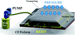
Optimum value of viscosity required for this process is lower than 0.3 Pa s. In literature, it is possible to find a theoretical maximum limit of 0.8 Pa s.22 Often a nanofilled resin exceeds the limit of 0.8 Pa s; then the usual liquid infusion becomes unfeasible. To overcome this critical point, a thin layer of liquid epoxy mixture containing MWCNTs (0.5% wt) was spread on a release films (Release Ease 234 TFP-HP Airtech); then a dry preform (400 mm × 400 mm) made laminating 7 plies of carbon fiber cloths (SIGMATEX (UK) LDT 193GSM (grams square meter)/PW (plain wave)/HTA40 E13 3K (3000 fibers each tow)) was placed on mixture forcing it to flow throw the thickness of the preform using an external supplementary pressure inside an autoclave. In this way the length of the impregnation path is considerably reduced and the process can be forced by means of the pressure application. A further advantage of this technology is associated to the smaller length of the infiltration path which reduces the effects of infiltration through the preform, ensuring in this way a more uniform distribution of the nanofiller through the panel thickness. In fact, the edges of the preform were sealed to force the resin to flow only through the thickness (see Fig. 2A). The laminate was covered by a porous release film and a distribution media to allow to the resin to escape from the upper side and a breather media to receive the excesses of the resin (see Fig. 2B). Finally it was placed in a vacuum bag and the laminate was transferred into the autoclave (see Fig. 2C).
2.2. Methods
Nanofilled resin T20BDCNTs. Fracture surfaces of the composite specimens T20BDCNTs were investigated after etching procedure to remove a fraction of resin and better evidence the morphological feature. Micrographs were captured with a LEO 1525 Scanning Electron Microscope (SEM).
Panels of CFRCs. Strips of CFRCs were cut out from the panels and analyzed in direction parallel (i.e. in plane) and perpendicular (i.e. out of plane) to the panel plane. Some of the samples were treated with a strong etching reagent and observed using conventional techniques of Field Emission Scanning Electron Microscope (FESEM, mod. LEO 1525, Carl Zeiss SMT AG, Oberkochen, Germany). The etching reagent was prepared by stirring 1.0 g potassium permanganate in a solution mixture of 95 ml sulphuric acid (95–97%) and 48 ml orthophosphoric acid (85%). The filled resins were immersed into the fresh etching reagent at room temperature and held under agitation for 36 hours. Subsequent washings were done using a cold mixture of 2 parts by volume of concentrated sulphuric acid and 7 parts of water. Afterwards the samples were washed again with 30% aqueous hydrogen peroxide to remove any manganese dioxide. The samples were finally washed with distilled water and kept under vacuum for 5 days at room temperature. The samples were placed on a carbon tab previously stuck to an aluminum stub (Agar Scientific, Stansted, UK). The samples were covered with a 250 Å-thick gold film using a sputter coater (Agarmod. 108 A).
Before performing the electrical measurements, the samples are cleaned with acetone and thermally pretreated at 80 °C for 24 h. Then, contacts made with silver paint (Alpha Silver Coated Copper Compound Screening, with a thickness of about 50 μm and a resistivity of 0.7 Ω square) are deposited. In order to obtain the conductivity values, two multimeters (HP 34401A, HP 3408A) and an electrometer (Keithley 6514A) are used. A BINDER climatic chamber Model FP 53 has been used to analyze the temperature dependence of the conductivities in the range [30–90] °C with step ΔT = 10 °C.
The measurement of σv∥, is performed by using the 4-probe method as schematically shown in Fig. 3.
In Table 1 the geometrical dimensions of the electrode configuration are reported together with the relative uncertainty in the geometric dimensions in the form x ± Δx. In this case the conductivity of the material samples under test is calculated using the following expression:
 | (1) |
| Sample | a [cm] | Δa [cm] | b [cm] | Δb [cm] | c [mm] | Δc [mm] |
|---|---|---|---|---|---|---|
| Sample DST07 | 1.11 | 0.02 | 1.61 | 0.02 | 1.31 | 0.01 |
The measurement of σv⊥ is performed by using the 3-probe method with the configuration given in Fig. 4. This technique is adopted in order to avoid any superficial leakage currents.
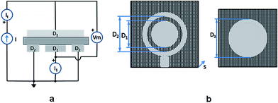 | ||
| Fig. 4 Arrangement for the measurement of the out of plane volumetric DC conductivity: electric circuit (a); geometric structure of the top and down electrodes (b). | ||
In Table 2 the geometrical dimensions of the electrode configuration for the square case DLS01 are reported together with the relative uncertainty in the geometric dimensions in the form x ± Δx.
| Sample | D 1 [cm] | ΔD1 [cm] | D 2 [cm] | ΔD2 [cm] | s [mm] | Δs [mm] |
|---|---|---|---|---|---|---|
| Sample DLS01 | 2.50 | 0.02 | 2.80 | 0.02 | 1.34 | 0.01 |
In Fig. 4, D1 and D2 are the diameter of the inner and outer electrode of the top side, respectively, D3 is the electrode diameter of the bottom side and s is the thickness of the CFRC sample.
By setting g and Kv equal to:
 | (2) |
The volume fraction was calculated using the following formula:
 | (3) |
3. Results and discussion
3.1. Nanofilled epoxy mixture
| σ = σ0(ϕ − ϕc)t | (4) |
The volume DC conductivity of the nanofilled epoxy mixture is σv = 0.142 S m−1 for the sample at a loading of 0.5 wt%. The obtained value confirms that the mixture is above the EPT. Also the measurements of the electrical properties in the frequency range [0.1; 1000] kHz, not shown here, confirm that the percolation threshold is in the range [0.1; 0.32]% wt and that at 0.5%wt the composite performs as a conducting material. In fact, the AC conductivity is constant in the analysed frequency range and close to the DC value. Moreover, the measured real part of the relative permittivity is about two order of magnitude greater (εr ≅ 1000) than the value obtained for the unfilled T20BD matrix, with a frequency dependence showing the dispersion typical of a loss material.
3.2. Carbon fiber reinforced panels
| Temperature [°C] | Pristine | 0.5% wt of MWCNTs |
|---|---|---|
| 80 | 5.26 | 7.83 |
| 90 | 2.11 | 5.82 |
| 100 | 0.96 | 4.49 |
| 110 | 0.52 | 3.58 |
| 120 | 0.31 | 3.05 |
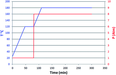
Data shown in Table 3 highlight that, although the viscosities of the unfilled and nanofilled resins have been strongly lowered with the mixing of the epoxy precursor with the reactive diluent, the usual liquid infusion process is not feasible. The technique described in the section “CFRCs – Manufacturing Process” allows to overcome these criticalities. Impregnation conditions (curing cycle and pressure) of CFRC panels is shown in Fig. 6.
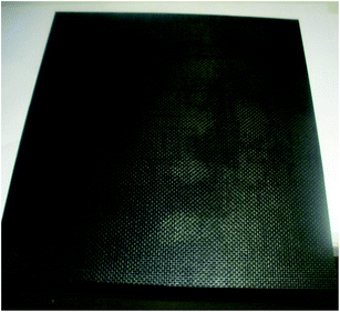
An optical picture of the manufactured panels is shown in Fig. 7.
All the manufactured panels are characterized by a calculated volume fiber fraction Vf between 0.55 and 0.56. Fig. 8a and b show the SEM images at two different magnification of the some cross sectional areas of the manufactured panel (not etched sample). Fig. 8a also clearly shows the number of plies.
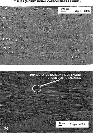 | ||
| Fig. 8 SEM images, at two different magnification, of the cross sectional area of the manufactured panel. | ||
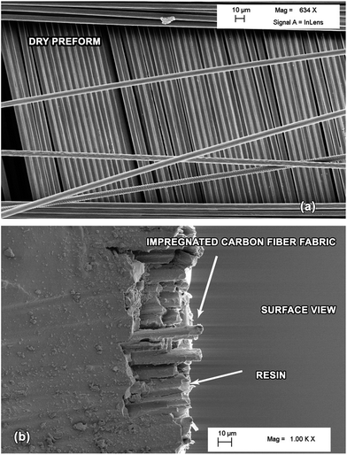
Because the investigated region is comprised between two nodes of the fabric mesh and relates to a sectional area (where the sample was punched out), we can deduce that a good interfacial bonding between carbon fiber fabric and epoxy resin has been achieved. FESEM image on the top side of the CFRC panel surface was acquired after a strong etching procedure and it is shown in Fig. 9. In this figure the dry preform fabric is also shown on the top to allow a comparison.
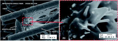
The image highlights that the carbon fibers are well impregnated by the nanofilled resin and therefore part of the surrounding resin is retained even also after the strong etching procedure. From the micrographs in Fig. 10a–d at lager magnification, it is possible to observe that the single fibers are completely impregnated by resin layers.
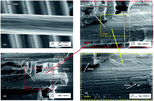 | ||
| Fig. 10 SEM micrographs of single carbon fiber (a); detail at different magnification (b), (c) and (d) of a single CF impregnated by the nanofilled resin. | ||
This effect is also well observable in Fig. 10 showing a comparison between the single fiber of the fabric (without resin) (Fig. 10a) with the impregnated fibers (Fig. 10b–d).
The observation that the single fibers are well coated by the nanofilled resin, even after a strong etching procedure, highlights strong attractive interactions between the carbon fibers and the nanofilled resins. The carbon nanotubes embedded in the epoxy resin can be observed when high magnification, as those chosen for the micrographs of Fig. 11 and 12, are set up. Fig. 11 evidences the presence of some carbon nanotubes arranged preferentially through the section of the panel in the direction perpendicular to the plane. This particular morphological feature may be the key factor causing the high out of plane electrical conductivity. The reason why this peculiar morphology is obtained is most likely due to the adopted infiltration process where the nanofilled resin is forced to flow through the thickness of the preform.
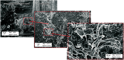 | ||
| Fig. 12 SEM micrographs of the etched surface on the top side of the CFR panel surface in the region which has not been broken by the cutting. | ||
Fig. 12 shows successively higher magnifications (from left to right) of the etched surface on the top side of the CFR panel surface in the region which has not been broken by the cutting. The images of Fig. 12 highlight a noteworthy result: the carbon nanotubes, dragged by the resin in which they are embedded, are able to pass through all the plies with no observable sieving effect. This result is certainly due the non-usual technique to infuse the nano-filled resin into the carbon fiber dry preform.
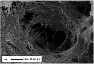
Although the image of the final composite is different from the nanofilled resin of Fig. 5 (the composite is much more compact due to the presence of the carbon fibers), it is possible to observe CNTs bridging all the epoxy-rich regions between the plies, giving rise to an efficient network as for the nanofilled resin (without CFs). The presence of this network between CNTs is confirmed by the electrical measurements. In fact, the out of plane conductivity (across the sample thickness) reaches the value of 3.9 S m−1. This value is among the highest value reached until now for nanofilled resins impregnating carbon fibers of panels obtainable through the proposed simple manufacturing process which can be scaled up to industrial levels.
| σv∥ = σfVf |
| This work | Ref. 30 | Ref. 24 | Ref. 31 | Ref. 29 | |
|---|---|---|---|---|---|
| σ v∥ [kS m−1] | 19.5 | — | 40.5(σx) − 0.20(σy) | 1 × 10⁻⁷ ÷ 1 × 10⁻⁶ (fiber direction 0°, +45°, −45°, 90°) | 14 (SWCNT), 11 (MWCNT) |
| σ v⊥ [S m−1] | 3.9 | 0.2 | 1.3 | 1 × 10⁻⁸ ÷ 1 × 10⁻⁷ | 5 (SWCNT), 9 (MWCNT) |
| # plies | 7 | 8 | 12 | 4-PET-binding yarn (glass fibers) | (Carbon fibers coated with CNTs) |
| Inter-ply fiber direction | 0° | 0° | 0–90° | (0°, +45°, −45°, 90°) | |
| Technique | Bulk infusion | Prepregs | — | RTM | VARTM |
In particular, the electrical conductivity values measured at room temperature for our panel (second column) are compared with those based on nanofilled epoxy resins already published in literature. In the case of ref. 31, Gojny et al. employs nanoparticle-reinforced FRP containing carbon black (CB) and CNTs epoxies as matrix for conventional glass fibre-reinforced panel (GFRP), manufactured via Resin Transfer Moulding process (RTM). The GFRP containing 0.3% wt of amino-functionalized double-wall carbon nanotubes (DWCNT-NH2) were found to exhibit an anisotropic electrical conductivity, with the in plane conductivity of fiber fabric of one order of magnitude higher than the transversal conductivity. Piche et al. in ref. 24 presented different experimental approaches to characterize the electric behaviour of carbon fiber composites used in aeronautic industry and a numerical model to support test definition and material characterization. The validation of the models with experimental tests allowed to extract values of electrical conductivities of fiber reinforced composite samples, once the appropriate method to perform the test is selected. The developed approach on a composite having 12 plies with 0/90° sequence of plies, allowed to obtain an out of plane volumetric conductivity of composites σv⊥ = 1.3 S m−1, and in plane values of σx∥ = 40.5 kS m−1 and σy∥ = 0.20 kS m−1. In our case (see column 2 in Table 4), the type of used fabric and the chosen lay-up direction allows to obtain an in plane value independent on the axis. Lonjon A. et al.30 obtained an electrical conductivity improvement of aeronautical carbon fiber reinforced polyepoxy composites by CNTs inclusion. Carbon fiber composite were prepared by prepregs, with epoxy multicomponent resin alone and with epoxy multicomponent resin filled with a small CNT weight fraction. Palmitic acid was used as dispersing agent of CNTs in epoxy systems, which enables the realization of the percolation threshold at low rates (about 0.4% wt of CNTs). For CF composites, 8 prepregs were assembled with unidirectional carbon fiber oriented in the same direction (0°). Electrical measurements of the volumetric conductivity of unfilled and filled were performed in the frequency domain [10−2; 106] Hz, at room temperature. The results highlights a poor conductivity value (σv⊥ ≅ 7.1 × 10⁻³ S m−1) in the out of plane measurement for the laminate obtained with unfilled resin. The addition of CNTs in the epoxy resin, causes a large increase in the conductivity of the laminate composites (σv⊥ ≅ 0.2 S m−1). Summing up, by considering the values shown in Table 4, we can conclude that the values exhibited by our panels for the out of plane conductivity are among the highest values obtained up to now with the exception of ref. 29, where higher values were achieved using a more complex manufacturing process. Although it is very hard to directly obtain conclusions from the comparison between the different data above discussed and shown in Table 4, because of the relevant differences in the epoxy chemical composition, nanofiller nature, concentration and manufacturing process, a comparison is the only potential way to address technological solutions towards the required targets in aeronautic field. Experiments are in progress to better understand the effect of the nature of the components and process manufacturing on the electrical properties.
4. Conclusions
In this paper we have shown the first results obtained using a non-usual technique to manufacture CFRCs. This technique is particularly advantageous to impregnate CFs with aeronautic resins filled with conductive nanofillers. In particular, the impregnation can be obtained also using an epoxy mixture characterized by viscosity values higher than 0.3 Pa s.The anisotropic volumetric DC conductivity of the CFRC is almost independent on temperature in the range [30; 90] °C and is about 20 kS m−1 for the in plane value and 3.9 S m−1 for the out of plane at T = 30 °C. This last value is among the highest value found for CFRCs impregnated with resins loaded with carbon nanotubes and manufactured by means of very simple processes.
Moreover, the in plane value confirm that the conduction mechanisms is governed by the fibers. In fact, the obtained volumetric conductivity of the strip sample is close to that of carbon fibers alone whose conductivity is around 104 to 105 S m−1. The value achieved for the out of plane conductivity which is almost one order of degree higher than that of the used nanofilled resin alone, shows that the electrical conduction is improved by the contribution of the percolating paths created by the MWCNTs inside the resin.
Acknowledgements
The research leading to these results has received funding from the European Union's Seventh Framework Programme for research, technological development and demonstration under Grant Agreement no. 313978.References
- J. K. Fink, Reactive Polymers Fundamentals and Applications: A Concise Guide to Industrial Polymers, Plastics Design Library (PDL), William Andrew, Norwich, NY, U.S.A, 2005, ISBN: 0-8155-1515-4 Search PubMed.
- C. A. May, Epoxy Resins Chemistry and Technology, Second edn, Revised and Expanded, ed. C. A. May, Marcel Dekker, Inc, New York, 1988, ISBN: 0-8247-7690-9 Search PubMed.
- L. Guadagno, L. Vertuccio, A. Sorrentino, M. Raimondo, C. Naddeo, V. Vittoria, G. Iannuzzo, E. Calvi and S. Russo, Mechanical and barrier properties of epoxy resin filled with multi-walled carbon nanotubes, Carbon, 2009, 47, 2419–2430 CrossRef CAS PubMed.
- J. K. W. Sandler, J. E. Kirk, I. A. Kinloch, M. S. P. Shaffer and A. H. Windle, Ultra-low electrical percolation threshold in carbon-nanotube–epoxy composites, Polymer, 2003, 44, 5893–5899 CrossRef CAS.
- R. Khare and S. Bose, Carbon nanotube based composites – A review, J. Miner. Mater. Charact. Eng., 2005, 4, 31–46 Search PubMed.
- L. Guadagno, B. De Vivo, A. Di Bartolomeo, P. Lamberti, A. Sorrentino, V. Tucci, L. Vertuccio and V. Vittoria, Effect of functionalization on the thermo-mechanical and electrical behavior of multi-wall carbon nanotube/epoxy composites, Carbon, 2011, 49, 1919–1930 CrossRef CAS PubMed.
- N. Hu, Z. Masuda, C. Yan, G. Yamamoto, H. Fukunaga and T. Hashida, The electrical properties of polymer nanocomposites with carbon nanotube fillers, Nanotechnology, 2008, 19, 215701–215711 CrossRef PubMed.
- D. S. Mclachlan, C. Chiteme, C. Park, K. E. Wise, S. E. Lowther, P. T. Lillehei, E. J. Siochi and J. S. Harrison, AC and DC percolative conductivity of single wall carbon nanotube polymer composites, J. Polym. Sci., Part B: Polym. Phys., 2005, 43, 3273–3287 CrossRef CAS.
- L. Guadagno, M. Raimondo, V. Vittoria, L. Vertuccio, K. Lafdi, B. De Vivo, P. Lamberti, G. Spinelli and V. Tucci, The role of carbon nanofiber defects on the electrical and mechanical properties of CNF-based resins, Nanotechnology, 2013, 24, 305704(10) CrossRef PubMed.
- B. E. Kilbride, J. N. Coleman, J. Fraysse, P. Fournet, M. Cadek, A. Drury, S. Hutzler, S. Roth and W. J. Blau, Experimental observation of scaling laws for alternating current and direct current conductivity in polymer-carbon nanotube composite thin films, J. Appl. Phys., 2002, 92, 4024–4030 CrossRef CAS PubMed.
- L. Guadagno, C. Naddeo, V. Vittoria, A. Sorrentino, L. Vertuccio, M. Raimondo, V. Tucci, B. De Vivo, P. Lamberti, G. Iannuzzo, E. Calvi and S. Russo, Cure behavior and physical properties of epoxy resin-filled with multiwalled carbon nanotubes, J. Nanosci. Nanotechnol., 2010, 10, 2686–2693 CrossRef CAS PubMed.
- B. De Vivo, P. Lamberti, V. Tucci, L. Guadagno, L. Vertuccio, V. Vittoria and A. Sorrentino, Comparison of the physical properties of epoxy-based composites filled with different types of carbon nanotubes for aeronautic applications, Adv. Polym. Technol., 2012, 31, 205–218 CrossRef CAS.
- L. Guadagno, M. Raimondo, V. Vittoria, L. Vertuccio, C. Naddeo, P. Lamberti and V. Tucci, Italian Patent Resina epossidica con basso tenore di umidità no. TO2013A000926, 15 November 2013.
- L. Guadagno, M. Raimondo, P. Longo, L. Bonnaud, O. Murariu and P. Dubois, Italian Patent Resina epossidica multifunzionale con accresciuta resistenza alla fiamma no. TO2013A001021, 13 December 2013.
- L. Guadagno, M. Raimondo, K. Lafdi, A. Fierro, S. Rosolia and M. R. Nobile, Influence of Nanofiller Morphology on the Viscoelastic Properties of CNF/Epoxy Resins, AIP Conf. Proc., 2014, 1599, 386–389 CrossRef CAS PubMed.
- M. R. N. Nobile, M. Raimondo, K. Lafdi, A. Fierro, S. Rosolia and L. Guadagno, Relationships between Nanofiller Morphology and Viscoelastic Properties in CNF/Epoxy Resins, Polym. Compos., 2015 Search PubMed , (accepted for publication).
- L. Guadagno, M. Raimondo, V. Vittoria, L. Vertuccio, C. Naddeo, S. Russo, B. De Vivo, P. Lamberti, G. Spinelli and V. Tucci, Development of epoxy mixtures for application in aeronautics and aerospace, RSC Adv., 2014, 4, 15474–15488 RSC.
- M. Raimondo, S. Russo, L. Guadagno, P. Longo, S. Chirico, A. Mariconda, L. Bonnaud, O. Murariu and Ph. Dubois, Effect of Incorporation of POSS compounds and phosphorous hardeners on Thermal and Fire Resistance of nanofilled Aeronautic Resins, RSC Adv. Search PubMed , (in revision).
- B. De Vivo, L. Guadagno, P. Lamberti, M. Raimondo, G. Spinelli, V. Tucci, L. Vertuccio and V. Vittoria, Electrical properties of multi-walled carbon nanotube/tetrafunctional epoxy–amine composites, AIP Conf. Proc., 2012, 1459, 199–201 CrossRef CAS PubMed.
- M. Raimondo and L. Guadagno, Effect of incorporation of carbon nanotubes on the mechanical properties of epoxy–amine composites, AIP Conf. Proc., 2012, 1459, 226–228 CrossRef CAS PubMed.
- F. Hussain, M. Hojjati, M. Okamoto and R. E. Gorga, Review article: Polymer–matrix Nanocomposites, Processing, Manufacturing, and Application: An Overview, J. Compos. Mater., 2006, 40, 1511–1575 CrossRef CAS PubMed.
- J. Summerscales and T. J. Searle, Low Pressure (Vacuum Infusion) Techniques for Moulding Large Composite Structures, Proc. Inst. Mech. Eng., Part L, 2005, 219, 45–58, DOI:10.1243/146442005X10238.
- D. D. L. Chun, Carbon Fiber Composites, ed. D. L. Chun Deborah, Butterworth-Heinemann, 313 Washington Street Newton, MA 02158, 1994, ISBN: 0-7506-9169-7 Search PubMed.
- A. Piche, I. Revel and G. Peres, Experimental and Numerical Methods to Characterize Electrical Behaviour of Carbon Fiber Composites Used in Aeronautic Industry, in Advances in Composite Materials – Analysis of Natural and Man-Made Materials, ed. Pavla Tesinova, Publisher InTech, Rijeka, Croatia, 2011, ch. 20, pp. 481–496, ISBN 978-953-307-449-8 Search PubMed.
- N. Athanasopoulos and V. Kostopoulos, Prediction and experimental validation of the electrical conductivity of dry carbon fiber unidirectional layers, Composites, Part B, 2011, 42, 1578–1587 CrossRef PubMed.
- M. Weber and M. R. Kamal, Estimation of the volume resistivity of electrically conductive composites, Polym. Compos., 1997, 18, 711–725 CrossRef CAS.
- V. Šafářová and J. Grég, Electrical conductivity measurement of fibers and yarns, 7th International Conference, TEXSCI, Liberec, Czech Republic, September 6–8, 2010 Search PubMed.
- O. Keiji and T. Yoshihiro, Electrical properties of carbon fiber reinforced plastics and their application, J. Jpn. Soc. Compos. Mater., 2002, 28, 228–234 CrossRef.
- E. Bekyarova, E. T. Thostenson, A. Yu, H. Kim, J. Gao, J. Tang, H. T. Hahn, T. W. Chou, M. E. Itkis and R. C. Haddon, Multiscale Carbon Nanotube-Carbon Fiber Reinforcement for Advanced Epoxy Composites, Langmuir, 2007, 23, 3970–3974 CrossRef CAS PubMed.
- A. Lonjon, P. Demont, E. Dantras and C. Lacabanne, Electrical conductivity improvement of aeronautical carbon fiber reinforced polyepoxy composites by insertion of carbon nanotubes, J. Non-Cryst. Solids, 2012, 358, 1859–1862 CrossRef CAS PubMed.
- F. H. Gojny, M. H. G. Wichmann, B. Fiedler, W. Bauhofer and K. Schulte, Influence of nano-modification on the mechanical and electrical properties of conventional fibre-reinforced composites, Composites, Part A, 2005, 36, 1525–1535 CrossRef PubMed.
| This journal is © The Royal Society of Chemistry 2015 |

