 Open Access Article
Creative Commons Attribution 3.0 Unported Licence
Enzymatically degradable EMI shielding materials derived from PCL based nanocomposites
Shital Patangrao
Pawar
,
Sachin
Kumar
,
Anupam
Misra
,
Subrajeet
Deshmukh
,
Kaushik
Chatterjee
and
Suryasarathi
Bose
 *
*
Department of Materials Engineering, Indian Institute of Science, Bangalore-560012, India. E-mail: sbose@materials.iisc.ernet.in
First published on 23rd January 2015
Abstract
In this study, two different types of multiwall carbon nanotubes (MWNTs) namely pristine (p-MWNTs) and amine functionalized (a-MWNTs) were melt-mixed with polycaprolactone (PCL) to develop biodegradable electromagnetic interference (EMI) shielding materials. The bulk electrical conductivity of the nanocomposites was assessed using broadband dielectric spectroscopy and the structural properties were evaluated using dynamic mechanical thermal analysis (DMTA). Both the electrical conductivity and the structural properties improved after the addition of MWNTs and were observed to be proportional to the increasing fractions in the nanocomposites. The shielding effectiveness of the nanocomposites was studied using a vector network analyzer (VNA) in a broad range of frequencies, X-band (8 to 12 GHz) and Ku-band (12 to 18 GHz) on toroidal samples. The shielding effectiveness significantly improved on addition of MWNTs, more in the case of p-MWNTs than in a-MWNTs. For instance, at a given fraction of MWNTs (3 wt%), PCL with p-MWNTs and a-MWNTs showed a shielding effectiveness of −32 dB and −29 dB, respectively. Moreover, it was observed that reflection was the primary mechanism of shielding at lower fractions of MWNTs, while absorption dominated at higher fractions in the composites. As one of the rationales of this work was to develop biodegradable EMI shielding materials to address the challenges concerning electronic waste, the effect of different MWNTs on the biodegradability of PCL composites was assessed through enzymatic degradation. The enzymatic degradation of the samples cut from the hot pressed films by bacterial lipase was investigated. It was noted that a-MWNTs exhibited almost similar degradation rate as the control PCL sample; however, p-MWNTs showed a slower degradation rate. This study demonstrates the potential use of PCL-MWNT composites as flexible, light weight and eco-friendly EMI shielding materials.
Introduction
Owing to its versatility, polymeric nanocomposites have gained tremendous commercial importance and are being explored in a wide range of applications ranging from infrastructure, military and automotive to electronic industry. Due to the advancement in electronic industry, electronic-waste (e-waste) is increasing enormously. In order to manage the e-waste, recycling and degradation of electronic components such as control panels, switches, printed circuit boards, instrument cabinets, have become vital. In order to minimize the e-waste, the development of biodegradable materials for various applications is in great demand. Typical biodegradable polymers comprises of ester linkage, which can easily be attacked by enzymes,1 leading to their degradation. Among the various biodegradable polymers, poly(ε-caprolactone), PCL has emerged as an important candidate1–7 for polymer based nanocomposites for various applications due to its ease of processing. However, poor mechanical properties and its insulating nature limit its use in structural and electronic applications. Various strategies, such as blending with another polymer8–10 or addition of functional nanoparticles,11–16 have been adopted in the recent past to improve the properties of PCL.In recent times, there has been a significant increase in a new type of pollution in the form of Electromagnetic interference (EMI) owing to the increasing number of electronics and telecommunication devices. EMI is responsible for the malfunctioning of electronic equipments and can also adversely affect human health. Therefore, it is not surprising that a large volume of research is being dedicated toward developing materials that can reduce EMI.17–25 In this context, different types of materials, such as metals, intrinsically conducting polymers (ICPs), and conducting polymer composites (CPCs), have been explored to attenuate the EM radiations. However, these materials suffer from different limitations. For instance, ICPs present processing difficulties, and moreover it has to be doped in order to make them conducting, which requires additional preparation steps. In addition, metals are difficult to process and are prone to corrosion. Hence, most of the studies have been dedicated to fabricate conducting polymer nanocomposites involving conducting fillers such as carbon black (CB), carbon nanofibers (CNFs), carbon nanotubes (CNTs) and metal nanoparticles. Among the other particles, CNTs26 have proven to be the most effective on account of their high electrical and thermal conductivity, high aspect ratio and superior mechanical properties. It is well studied and documented that owing to their high aspect ratio, CNTs form conducting networks in polymer matrixes at relatively low fraction. This eventually leads to highly conducting nanocomposites. However, the key challenge associated with CNTs is the difficulty to homogenously disperse them in a given polymer matrix. A recent review27 addresses various challenges in dispersing CNTs and also highlights various surface treatments of CNTs.
In light of this, we made an attempt to develop biodegradable nanocomposites for EMI shielding applications in this study. This issue has been addressed here in the context of reducing e-waste that contains large amounts of components made of polymer based composites. Two key properties required for EMI shielding applications are high electrical conductivity and good mechanical strength. In order to improve the electrical and mechanical properties of PCL, two different types of MWNTs were melt mixed, an industrially viable route to produce composites in large scale. The state of dispersion of MWNTs was assessed using a scanning electron microscopy (SEM) and broadband dielectric spectroscopy. The mechanical properties of the nanocomposites were evaluated as a function of temperature using dynamic mechanical thermal analyzer. The shielding effectiveness of the nanocomposites was studied using a vector network analyzer in a broad range of frequencies, X-band and Ku-band. In order to elucidate its degradation enzymatically, we evaluated the degradation of PCL in the presence of a Pseudomonas lipase, which is capable of cleaving ester bonds in PCL. Films were subjected to enzymatic degradation at 37 °C in an enzyme containing pH 7 phosphate buffer solution. The results obtained from various analytical techniques are presented herein.
Experimental section
Materials
Poly(ε-caprolactone) (PCL, average molecular weight Mn = 45![[thin space (1/6-em)]](https://www.rsc.org/images/entities/char_2009.gif) 000 g mol−1) was obtained from Sigma-Aldrich in pellet form. Both pristine (p-MWNTs) and amine functionalized multiwall carbon nanotubes (a-MWNTs) were obtained from Nanocyl SA Belgium. The characteristics dimensions of p-MWNTs are 9.5 nm (average diameter) and 1.5 μm (average length) and those of a-MWNTs are 9.5 nm (average diameter) and 900 nm (average length). Pseudomonas lipase was obtained from Sigma.
000 g mol−1) was obtained from Sigma-Aldrich in pellet form. Both pristine (p-MWNTs) and amine functionalized multiwall carbon nanotubes (a-MWNTs) were obtained from Nanocyl SA Belgium. The characteristics dimensions of p-MWNTs are 9.5 nm (average diameter) and 1.5 μm (average length) and those of a-MWNTs are 9.5 nm (average diameter) and 900 nm (average length). Pseudomonas lipase was obtained from Sigma.
Preparation of the nanocomposites
Nanocomposites of PCL were processed by melt mixing using a Haake Mini lab II melt compounder. Prior to melt mixing, the p-MWNTs were dispersed in tetrahydrofuran (THF) using a probe sonicator for 15 min (Hielsher, Ultrasound technology) followed by bath sonication for 45 min. The obtained powder was finally vacuum dried for 48 h at 80 °C. The a-MWNTs were used as received without any pre-treatment. PCL pellets were dried at 40 °C under vacuum for 24 h prior to melt mixing. All the nanocomposites were processed at 80 °C for 20 min at a screw speed of 60 rpm and under nitrogen atmosphere. Various PCL/MWNT composites were prepared by varying the concentration of MWNTs as 1, 2 and 3 wt% of the total batch size.Characterization
Dispersion of MWNTs in PCL matrix was analyzed using FEI Sirion XL Fe30 FEG SEM, on cryo-fractured extruded strands. Mechanical properties in the temperature range of −80 °C to 25 °C was studied for various PCL nanocomposites using a Q800 (TA, instruments) dynamic mechanical analyzer in the tension mode at 1 Hz. Specimens of required dimensions (25 mm × 6.5 mm × 1 mm) were compressed molded at 80 °C. All the experiments were carried out in the linear viscoelastic region, determined apriori. Each experiment was repeated three times with a fresh sample, and errors of 2–3% were noted.Room temperature electrical conductivity of the nanocomposites in the frequency range of 0.1 Hz to 10 MHz was analyzed using Alpha-N Analyser, Novocontrol (Germany). Compression molded discs were used as specimens for these experiments.
Enzymatic degradation of control and PCL nanocomposites was carried out in a 1 mg ml−1 pseudomonas lipase solution in pH 7 phosphate buffered saline (PBS) at 37 °C. The specimens used were 25 mg thin films cut from the compression molded samples. The samples were placed in nylon mesh bags and placed in a 20 ml solution of the enzyme-containing buffer. These tubes were placed in an incubator-shaker (N-Biotek NB-205QF) at 37 °C and 100 rpm. After every 24 h, the samples were removed from the incubator and dried under vacuum to constant weight. The weight losses of the samples were recorded at an interval of 24 h for 10 days. All the measurements were performed in triplicates and the data are presented as mean ± S.D.
EMI shielding of the nanocomposites was carried out using an Anritsu MS4642A vector network analyzer (VNA) coupled to a coax (Damaskos M07T) set up. Prior to the measurements, the transmission line and the sample holder were calibrated by a two port (Short-open-load-transmission). Toroidal samples were hot pressed at 80 °C and were used for EMI shielding measurements. The EMI shielding experiments were carried out at room temperature. Total EMI SE was extracted from the scattering parameters (S11, S12, S22 and S21) in X-band (8–12 GHz) and Ku-band (12–18 GHz) frequency.
Results and discussion
State of dispersion of MWNTs in PCL
In order to assess the state of dispersion of p-MWNTs and a-MWNTs in PCL matrix, SEM micrographs of cryo-fractured composites were recorded. Fig. 1 shows the SEM micrographs of PCL composites with a-MWNTs and p-MWNTs. It is observed that both the MWNTs are relatively well dispersed in the PCL matrix, as can be seen by the white dots denoted by arrows in Fig. 1. As a general observation, the quality of dispersion of a-MWNTs is better than that of p-MWNTs. This can be attributed to specific interactions between the functional groups on a-MWNTs and PCL. It is well understood that beyond the percolation threshold, the conducting particles form a network-like structure and has a significant effect on the bulk electrical conductivity of the composites, and in turn, on the EM shielding. These properties will be discussed in the subsequent sections.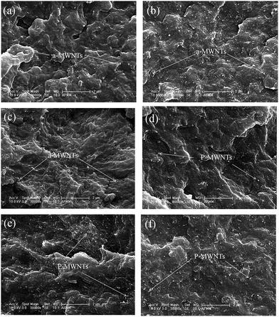 | ||
| Fig. 1 SEM micrographs of PCL composites with 1, 2 and 3 wt% a-MWNTs respectively (a–c) and 1, 2 and 3 wt% p-MWNTs, respectively, (d–f). | ||
Dynamic mechanical properties
The dynamic mechanical properties as a function of temperature for PCL nanocomposites were studied under the tension mode. The storage modulus (E′) for PCL with a-MWNTs and p-MWNTs are illustrated in Fig. 2(a) and (b), respectively. In all the composites, it is observed that the storage modulus gradually decreased when the temperature increases, a typical characteristic of brittle to ductile transition in polymers. In the case of neat PCL, a drastic decrease in the storage modulus is observed at −40 °C, which corresponds to the glass transition (Tg) temperature. Interestingly, after the addition of MWNTs, the storage modulus, especially in the glassy region, was significantly enhanced, although no significant change is observed in the Tg. For instance, in the glassy region (−70 °C) the neat PCL showed a storage modulus of 3160 MPa, whereas the addition of 1 wt% a-MWNTs and 1 wt% of p-MWNTs exhibited a significant increase in the storage modulus to 3579 MPa and 3657 MPa, respectively. This increase in storage modulus of the nanocomposites is consistent with the increasing fraction of MWNTs. This could be due to the relatively well dispersed MWNTs in the composites leading to improved mechanical properties.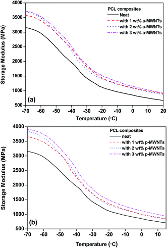 | ||
| Fig. 2 Storage modulus as a function of temperature for (a) PCL nanocomposites with a-MWNTs along with neat PCL and (b) PCL nanocomposites with p-MWNTs along with neat PCL. | ||
Bulk electrical conductivity and EMI shielding in the nanocomposites
Fig. 3 illustrates the room temperature AC electrical conductivity (σAC) as a function of frequency for various PCL/MWNTs composites. As expected, the neat PCL exhibited a linear increase in AC electrical conductivity as a function of frequency, which is a typical characteristic of an insulator. The electrical conductivity of PCL/MWNT nanocomposites increases along with the concentration of MWNTs in the composites. It is observed that there is a dramatic increase in the bulk electrical conductivity in the case of 1 wt% MWNTs along with a frequency independent plateau in the lower frequencies. This phenomenon clearly suggests that the electrical percolation threshold in PCL nanocomposites lies between 0–1 wt% in the case of both MWNTs. Moreover, this observation is consistent with the type of MWNTs used in this work. For instance, the p-MWNTs are longer by a factor of 2 with respect to a-MWNTs; hence, at any given fraction of MWNTs, the bulk electrical conductivity is expected to be higher in PCL/p-MWNTs than in PCL/a-MWNTs composites. Interestingly, it was also observed that the frequency independent plateau extended to higher frequencies with increasing fractions of MWNTs and it became almost independent over the entire measured frequency range. It is reported that the aspect ratio of the conducting nanoparticles has a great impact on the network formation and percolation threshold.28–31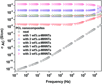 | ||
| Fig. 3 Alternate current electrical conductivity as a function of frequency for various PCL nanocomposites along with neat PCL. Red colored lines show power low fitting for respective nanocomposites. | ||
We have fitted the AC electrical conductivity scans using a power law to gain more insight into the mechanism of charge transport.32
| σ(ω) = σ(0)+ σac(ω) = σdc + Aωs |
![[thin space (1/6-em)]](https://www.rsc.org/images/entities/char_2009.gif) :
:![[thin space (1/6-em)]](https://www.rsc.org/images/entities/char_2009.gif) 26 and PCL/p-MWNTs represent 72
26 and PCL/p-MWNTs represent 72![[thin space (1/6-em)]](https://www.rsc.org/images/entities/char_2009.gif) :
:![[thin space (1/6-em)]](https://www.rsc.org/images/entities/char_2009.gif) 28 equivalent network of resistance and capacitance. It is evident from the exponent values that hopping dominates the charge transport at lower fractions and becomes tunneling at higher fractions through the fractal network of 3D MWNTs in the composites.
28 equivalent network of resistance and capacitance. It is evident from the exponent values that hopping dominates the charge transport at lower fractions and becomes tunneling at higher fractions through the fractal network of 3D MWNTs in the composites.
As one of the rationales of the paper is to develop biodegradable EMI shielding materials, the shield effectiveness was measured using a vector network analyzer on toroidal samples. In order to shield electromagnetic radiations, three basic mechanisms have been reported, namely, absorption, reflection and multiple reflections.21,33,34 EMI shielding materials must possess high electrical conductivity and electrical/magnetic dipoles. Shielding of EM radiations due to reflection is characteristic of materials with free charge carriers. However, absorption requires the presence of electrical and magnetic dipoles.35 These dipoles interact with the incident EM radiation and results in further eddy ohmic losses. Absorption losses are strongly dependent on the thickness and often increase with the thickness of the shielding material. Multiple reflections have negative effect on SE and can be neglected for absorption losses above 10 dB.
In this study, the shielding effectiveness was analyzed in broad range of frequencies, X-band (8–12 GHz) and the Ku-band (12–18 GHz). The X-band frequency is important in the case of commercial, as well as military applications such as transmission line, TV signals and radar transmission systems. Because the total shielding effectiveness is the summation of shielding through absorption (SEA), reflection (SER) and multiple reflections (SEMR), materials exhibiting both reflection and absorption are in great demand. A schematic explaining how the scattering parameters are derived from VNA is shown in Fig. 4a, the mechanism of shielding in composites in Fig. 4b and the VNA attached to a coax set up in Fig. 4c. Total shielding effectiveness can be mathematically expressed as SET = SER + SEA + SEMR. This can be further calculated by knowing the ratio of transmitted to incident power using the following equations:36–38
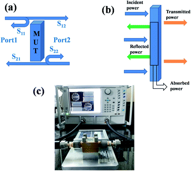 | ||
| Fig. 4 (a) Schematic representation showing the scattering parameters extracted from two-port VNA, (b) mechanism of shielding and (c) VNA and the coax set up. | ||
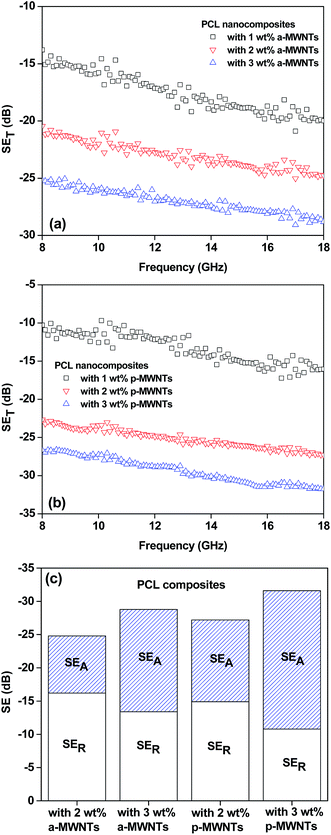
Fig. 5a and b depicts the total shielding effectiveness as a function of frequency for various PCL nanocomposites. The total SE was observed to increase with increasing fractions of MWNTs, irrespective of the type of MWNTs. This is consistent with the observed bulk electrical conductivity of the composites. For instance, the total shielding effectiveness increased from 16 dB for PCL with 1 wt% p-MWNTs to 32 dB for PCL with 3 wt% p-MWNTs at a particular frequency (18 GHz). The relatively higher electrical conductivity and the shielding effectiveness in the nanocomposites suggest an efficient dispersion of MWNTs. Although the a-MWNTs are shorter by a factor of 2 with respect to p-MWNTs, the shielding effectiveness values are only moderately lower than those of p-MWNTs. It is well understood that the functional groups present on the surface of the MWNTs facilitate an improved dispersion in the matrix.39 As discussed earlier, the network-like structure of the conducting nanoparticles enhances the attenuation of EM radiations. Interestingly, at higher fractions of MWNTs (>2 wt%), the nanocomposites exhibited an attenuation of EM radiations mostly through absorption.
Fig. 5c depicts the contribution of reflection and absorption to the total EM shielding effectiveness for PCL composites. It is clearly evident that, at 2 wt% of MWNTs loading, the reflection is the dominating mechanism, whereas at 3 wt% MWNTs loading, the absorption is dominating the attenuation process. Similar observation is reported by Liu et al.33 in the case of polyurethane composites with single walled carbon nanotubes (SWNTs), where the attenuation mechanism shifted from reflection to absorption at higher fractions of SWNT loading.
In the case of uniformly conducting shields, the shield thickness has no effect on the reflection mechanism, whereas for multi component systems, such as polymer composites, an increase in shield thickness results in the enhancement of SE through both reflection and absorption. In addition, the shielding mechanism is also dependent on electrical conductivity and connectivity of the conducting nanoparticles, which dictates the spacing between MWNTs in a given polymeric shield. Increasing electrical conductivity and decreasing spacing between MWNTs result in an enhanced attenuation through absorption. A similar observation is also evident in PCL based composites studied in this work, where at lower concentrations of MWNTs, the spacing between MWNTs is very high (less connectivity), and reflection seems to be the dominant mechanism of shielding. In the case of composites with higher concentrations of MWNTs, where spacing between MWNTs is very small (high connectivity), absorption is the dominant mechanism. The shielding mechanism in PP/MWNTs composites was discussed in detail by Al-Saleh et al.19 It was observed that 1 vol% (approx: 2 wt%) MWNTs resulted in 56% attenuation through absorption, which increased to 84% with 5 vol% MWNT in PP. Furthermore, in the case of epoxy composites with single walled carbon nanotubes (SWNTs) Li et al.40 showed that the contribution of reflection is much more than that one of absorption. Similarly, Yang et al.41 reported that reflection is the main mechanism of shielding in polystyrene composites with carbon nanotubes. In this work, PCL composites with MWNTs also showed a similar type of attenuation behavior, as reported in the literature where absorption is dominating at higher fractions of MWNTs. In the case of PCL composites with 2 wt% a-MWNTs and p-MWNTs, the absorption was ca. 34.6% and ca. 45.2%, respectively. However, at 3 wt% loading of a-MWNTs and p-MWNTs SE through absorption was increased to ca. 53.5% and ca. 66%, respectively. The composites with 3 wt% p-MWNTs manifested in highest SE through absorption and can be attributed to enhanced relative permittivity leading to the absorption of electric fields.
In order to assess the effect of the shield thickness on the EM attenuation, specimens with different thicknesses were studied here. Fig. 6a illustrates the total shielding effectiveness as a function of shield thickness for various PCL composites with 3 wt% p-MWNTs. It was observed that the total SE increased along with the thickness of the specimen. This enhanced attenuation is mainly due to the increased absorption (not shown here) with increasing thickness of the shield. These observations show that shield thickness and the fraction of conducting filler has prominent effects on the attenuation mechanism. The absorption component increased along with the shield thickness. It is well known that electromagnetic waves of very high frequencies cannot penetrate into an electrically conducting shield. The strength of the radiation decreases exponentially as it penetrates into the shield, and the critical thickness at which the EM radiation field strength drops to 1/e of the incident field is known as skin depth. The skin depth is dependent on the frequency, permeability and conductivity of shield and can be estimated from the following expression:42
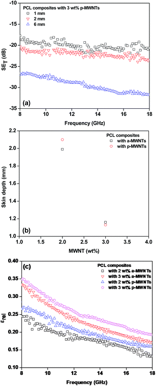 | ||
| Fig. 6 (a) Total shielding effectiveness as function of frequency at different thicknesses, (b) skin depth as function of wt% of MWNT loading and (c) relative permittivity as function of frequency. | ||
In order to comprehend the attenuation mechanism, we evaluated the permittivity values of PCL composites, which were estimated through the backward and the forward scattering parameters using the Nicolson and Ross line theory.44 The reflection coefficient of the incident wave on the specimen and line interface of toroidal specimen with known thickness can be expressed using the following equation:
The transmitting coefficient for toroidal specimen across the thickness can be expressed as follows:
V
1 and V2 are sum and difference of scattering parameters, respectively
| V1 = S21 + S11 |
| V1 = S21 − S11 |
Scattering parameters can be used to estimate the reflection coefficient (Γ) using the following expression:
 , and in order to satisfy the condition of |Γ| ≤ 1, the appropriate sign was chosen.
From relation 1,
And from relation 2,
Complex permittivity and permeability can be presented as
The relative permittivity obtained through scattering parameters as a function of frequency for PCL composites is illustrated in Fig. 6c. PCL composites with 2 wt% a-MWNTs and 2 wt% p-MWNTs manifested in 0.24 and 0.27, respectively, at 18 GHz frequency, whereas higher loading of MWNTs showed increased relative permittivity. The PCL composites with 3 wt% p-MWNTs manifested the highest permittivity among the composites, 0.35. This particular composite also resulted in the highest attenuation of EM radiation.
As mentioned earlier, different attenuation mechanisms are responsible for EM shielding, namely, reflection, absorption and multiple reflections. Multiple reflections can be ignored for specimens with absorption more than 10 dB, or if the shield thickness is more than the skin depth. In order to have insight of attenuation mechanisms for PCL composites, the shielding effectiveness through absorption and reflection were estimated using S parameters obtained from vector network analyzer using following relations:
| SEA = 10 × log10((1 − S112)/S122) |
| SER = 10 × log10(1/(1 − S112)) |
Enzymatic degradation: effect of MWNTs
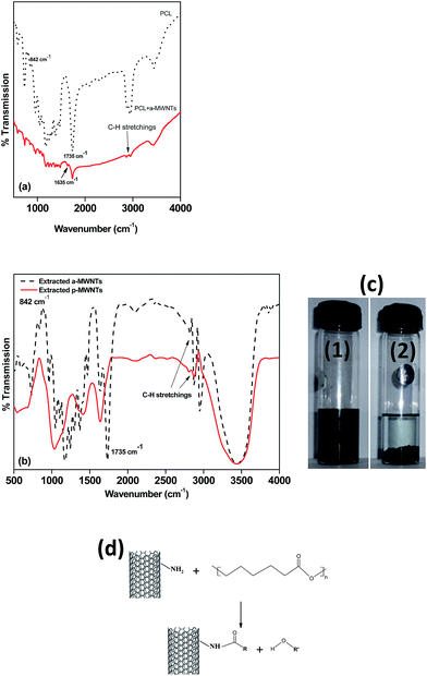
The effect of different MWNTs on the biodegradability of PCL composites was assessed through enzymatic degradation. The enzymatic degradation of samples, cut from the hot pressed films, was investigated at 37 °C in a pH 7 phosphate buffer containing pseudomonas lipase. Fig. 7 shows the weight loss as a function of the incubation time for neat PCL and its nanocomposites. From this study, it is clearly evident that PCL has significant degradability in enzymatic environment. In the presence of pseudomonas lipase, PCL showed 66% weight loss in 10 days. PCL nanocomposites with p-MWNTs showed a dramatic reduction in the degradation rate. The PCL composites with 3 wt% p-MWNTs resulted in negligible (6 wt%) degradation, even after 10 days of exposure. Paul et al.45 reported that the rate of hydrolytic degradation strongly depends on the surface water-wettability of the nanocomposites. In the case of PCL nanocomposites, Kumar et al.46 showed that the nanocomposites with p-MWNTs are more hydrophobic in nature, in striking contrast to what happens to the neat PCL. Therefore, the suppression of degradation rate of PCL nanocomposites could be attributed to its hydrophobic nature. Interestingly, composites with a-MWNTs manifested nearly the same degradation rate as that of neat PCL. In order to gain more insight into this behavior, we took a closer look at the nature of interactions between PCL and a-MWNTs. The melt mixed composites were dissolved in chloroform to remove the PCL phase and the nanoparticles obtained were filtered and dried. The FTIR spectra of the neat PCL and PCL/a-MWNT composites are shown in Fig. 8a. The characteristic peak at 1734 cm−1 corresponding to the ester groups of PCL is evident from the spectra. Similarly, the characteristic C–H stretching peaks corresponding to MWNT in the range of 2800 to 2900 cm−1 is also evident in both p-MWNT and a-MWNTs. In addition, in the PCL/a-MWNT nanocomposites a peak at 1635 cm−1 that corresponds to ester-amide linkage is observed. The FTIR spectra of the extracted nanoparticles from the composites are shown in Fig. 8b. Interestingly, the presence of ester groups of PCL on the surface of the remaining a-MWNTs clearly indicates the interaction between a-MWNTs and PCL. This was not observed in the case of extracted p-MWNTs. These findings are indicative of covalently-bound PCL on a-MWNTs, which did not dissolve in chloroform. In contrast, due to the lack of strong covalent interactions between PCL and p-MWNTs, the PCL matrix was fully dissolved plausibly because the chains were only physically adsorbed. The interaction of a-MWNTs with PCL is further supported by the solution dissolution test, where a fixed amount of the composite samples were dissolved in chloroform and sonicated for few minutes (see Fig. 8c). It is evident that a-MWNTs suspends well (vial 1 in Fig. 8c) in the solution, in striking contrast to p-MWNTs, which quickly settles down (vial 2 in Fig. 8c) after the initial sonication process. The possible reaction mechanism is schematically illustrated in Fig. 8d. This presumably can explain the faster degradation rate in PCL/a-MWNTs. Moreover, as mentioned earlier, the addition of a-MWNTs increases surface hydrophilicity in the nanocomposites, facilitating the faster degradation of PCL, in contrast to p-MWNTs.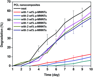 | ||
| Fig. 7 Temporal degradation profile of PCL nanocomposites at 37 °C in a pH 7 phosphate buffer containing pseudomonas lipase. | ||
The Scanning Electron Microscopy (SEM) images of PCL and its nanocomposites were assessed to analyze the morphological changes due to the degradation process. Fig. 9 depicts the SEM micrographs of PCL and its nanocomposites after the degradation tests at 10 days. It is observed that neat PCL has gone though profound degradation, and this is manifested from the cracks that appeared on the surface (see Fig. 9a). The morphology of the PCL/p-MWNTs films exhibited no significant change (Fig. 9b) and is consistent with the degradation kinetics, as observed in Fig. 7. In the case of PCL with a-MWNTs (Fig. 9c), similar morphological features were recorded as that of neat PCL.
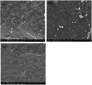 | ||
| Fig. 9 SEM micrographs of the sample surface after 10 days of enzymatic degradation for (a) neat PCL, (b) PCL with 3 wt% p-MWNTs and (c) PCL with 3 wt% a-MWNTs. | ||
To summarize, we have developed biodegradable nanocomposites based on PCL and MWNTs, which can be explored as potential EMI shielding films. A schematic figure (Fig. 10) further illustrates how these eco-friendly nanocomposites can significantly contribute toward the reduction of e-waste, which is a major concern at the present time.
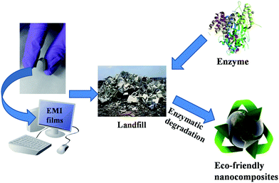 | ||
| Fig. 10 A schematic illustration of enzymatically degradable PCL/MWNT composites as potential eco friendly EMI shielding materials. | ||
Conclusion
Bio-degradable nanocomposites with enhanced microwave attenuation ability were designed from PCL and MWNTs. Two different types of MWNTs were incorporated in the PCL matrix by melt mixing process. PCL nanocomposites with 3 wt% p-MWNTs and a-MWNTs manifested SE of −32 and −29 dB, respectively, which shows an approximately 99% attenuation of incident radiation. The enzymatic degradation of the samples, cut from the hot pressed films by bacterial lipase was investigated. It was noted that a-MWNTs exhibited almost the same degradation rate as the control PCL; however, p-MWNTs showed a slower degradation rate. This study opens new avenues in designing biodegradable PCL/MWNT based composites that can be explored as potential EMI shielding materials. These nanocomposites may contribute extensively to control the e-waste generated due to electronic equipments.Acknowledgements
The authors would like to acknowledge the department of science and technology (DST), India for furnishing financial support. K.C. acknowledges support from DST Ramanujan fellowship.References
- K. Cho, J. Lee and P. Xing, J. Appl. Polym. Sci., 2002, 83, 868–879 CrossRef CAS.
- F. Causa, P. A. Netti, L. Ambrosio, G. Ciapetti, N. Baldini, S. Pagani, D. Martini and A. Giunti, J. Biomed. Mater. Res., Part A, 2006, 76, 151–162 CrossRef CAS PubMed.
- L. S. Nair and C. T. Laurencin, Prog. Polym. Sci., 2007, 32, 762–798 CrossRef CAS.
- C. V. Benedict, J. A. Cameron and S. J. Huang, J. Appl. Polym. Sci., 1983, 28, 335–342 CrossRef CAS.
- W. J. Cook, J. A. Cameron, J. P. Bell and S. J. Huang, J. Polym. Sci., Polym. Lett. Ed., 1981, 19, 159–165 CrossRef.
- I. Arvanitoyannis, A. Nakayama, N. Kawasaki and N. Yamamoto, Angew. Makromol. Chem., 1994, 222, 111–123 CrossRef CAS.
- M. A. Woodruff and D. W. Hutmacher, Prog. Polym. Sci., 2010, 35, 1217–1256 CrossRef CAS.
- C.-S. Wu, Polym. Degrad. Stab., 2003, 80, 127–134 CrossRef CAS.
- L. Cabedo, J. Luis Feijoo, M. Pilar Villanueva, J. M. Lagarón and E. Giménez, Macromol. Symp., 2006, 233(1), 191–197 CrossRef CAS.
- M. Todo, S.-D. Park, T. Takayama and K. Arakawa, Eng. Fract. Mech., 2007, 74, 1872–1883 CrossRef.
- B. Lepoittevin, M. Devalckenaere, N. Pantoustier, M. Alexandre, D. Kubies, C. Calberg, R. Jérôme and P. Dubois, Polymer, 2002, 43, 4017–4023 CrossRef CAS.
- W. Kai, Y. Hirota, L. Hua and Y. Inoue, J. Appl. Polym. Sci., 2008, 107, 1395–1400 CrossRef CAS.
- A. Arbelaiz, B. Fernández, A. Valea and I. Mondragon, Carbohydr. Polym., 2006, 64, 224–232 CrossRef CAS.
- B. Chen and K. Sun, Polym. Test., 2005, 24, 978–982 CrossRef CAS.
- M. C. Azevedo, R. L. Reis, M. B. Claase, D. W. Grijpma and J. Feijen, J. Mater. Sci.: Mater. Med., 2003, 14, 103–107 CrossRef CAS PubMed.
- B. Chen, K. Sun and T. Ren, Eur. Polym. J., 2005, 41, 453–457 CrossRef CAS.
- S. P. Pawar, K. Pattabhi and S. Bose, RSC Adv., 2014, 4, 18842–18852 RSC.
- H. Kim, K. Kim, C. Y. Lee, J. Joo, S. Cho, H. S. Yoon, D. A. Pejaković, J. W. Yoo and A. J. Epstein, Appl. Phys. Lett., 2004, 84, 589–591 CrossRef CAS.
- M. H. Al-Saleh and U. Sundararaj, Carbon, 2009, 47, 1738–1746 CrossRef CAS.
- D. D. L. Chung, Carbon, 2012, 50, 3342–3353 CrossRef CAS.
- M. H. Al-Saleh, W. H. Saadeh and U. Sundararaj, Carbon, 2013, 60, 146–156 CrossRef CAS.
- M. Sharma, S. Sharma, J. Abraham, S. Thomas, G. Madras and S. Bose, Mater. Res. Express, 2014, 1, 035003 CrossRef.
- R. Rohini and S. Bose, ACS Appl. Mater. Interfaces, 2014, 6, 11302–11310 CAS.
- S. P. Pawar, D.A. Marathe, K. Pattabhi and S. Bose, J. Mater. Chem. A, 2015, 3, 656–669 CAS.
- M. Sharma, M. P. Singh, C. Srivastava, G. Madras and S. Bose, ACS Appl. Mater. Interfaces, 2014, 6, 21151–21160 CAS.
- O. Breuer and U. Sundararaj, Polym. Compos., 2004, 25, 630–645 CrossRef CAS.
- X.-L. Xie, Y.-W. Mai and X.-P. Zhou, Mater. Sci. Eng., R, 2005, 49, 89–112 CrossRef.
- J. Li, P. C. Ma, W. S. Chow, C. K. To, B. Z. Tang and J. K. Kim, Adv. Funct. Mater., 2007, 17, 3207–3215 CrossRef CAS.
- S.-H. Yao, Z.-M. Dang, M.-J. Jiang, H.-P. Xu and J. Bai, Appl. Phys. Lett., 2007, 91, 212901 CrossRef.
- J. B. Bai and A. Allaoui, Composites, Part A, 2003, 34, 689–694 CrossRef.
- M. R. Ayatollahi, S. Shadlou, M. M. Shokrieh and M. Chitsazzadeh, Polym. Test., 2011, 30, 548–556 CrossRef CAS.
- K. L. Ngai, C. T. White and A. K. Jonscher, Nature, 1979, 277, 185–189 CrossRef CAS.
- Z. Liu, G. Bai, Y. Huang, Y. Ma, F. Du, F. Li, T. Guo and Y. Chen, Carbon, 2007, 45, 821–827 CrossRef CAS.
- K. Lakshmi, H. John, K. T. Mathew, R. Joseph and K. E. George, Acta Mater., 2009, 57, 371–375 CrossRef CAS.
- D. D. L. Chung, J. Mater. Eng. Perform., 2000, 9, 350–354 CrossRef CAS.
- B.P. Singh, Prabha, P. Saini, T. Gupta, P. Garg, G. Kumar, I. Pande, S. Pande, R. K. Seth, S. K. Dhawan and R. B. Mathur, J. Nanopart. Res., 2011, 13, 7065–7074 CrossRef CAS.
- Y.-E. Moon, J. Yun and H.-I. Kim, J. Ind. Eng. Chem., 2013, 19, 493–497 CrossRef CAS.
- A. P. Singh, M. Mishra, P. Sambyal, B. K. Gupta, B. P. Singh, A. Chandra and S. K. Dhawan, J. Mater. Chem. A, 2014, 2, 3581–3593 CAS.
- S. Bose, R. A. Khare and P. Moldenaers, Polymer, 2010, 51, 975–993 CrossRef CAS.
- N. Li, Y. Huang, F. Du, X. He, X. Lin, H. Gao, Y. Ma, F. Li, Y. Chen and P. C. Eklund, Nano Lett., 2006, 6, 1141–1145 CrossRef CAS PubMed.
- Y. Yang, M. C. Gupta, K. L. Dudley and R. W. Lawrence, Nano Lett., 2005, 5, 2131–2134 CrossRef CAS PubMed.
- T. K. Gupta, B. P. Singh, S. R. Dhakate, V. N. Singh and R. B. Mathur, J. Mater. Chem. A, 2013, 1, 9138–9149 CAS.
- K. Singh, A. Ohlan, V. H. Pham, R. Balasubramaniyan, S. Varshney, J. Jang, S. H. Hur, W. M. Choi, M. Kumar, S. K. Dhawan, B. S. Kong and J. S. Chung, Nanoscale, 2013, 5, 2411–2420 RSC.
- A. M. Nicolson and G. F. Ross, IEEE Trans. Instrum. Meas., 1970, 19, 377–382 CrossRef.
- M.-A. Paul, C. Delcourt, M. Alexandre, P. Degée, F. Monteverde and P. Dubois, Polym. Degrad. Stab., 2005, 87, 535–542 CrossRef CAS.
- S. Kumar, S. Bose and K. Chatterjee, RSC Adv., 2014, 4, 19086–19098 RSC.
| This journal is © The Royal Society of Chemistry 2015 |


