Improved catalytic activity and surface electro-kinetics of bimetallic Au–Ag core–shell nanocomposites†
Anila
Monga
and
Bonamali
Pal
*
School of Chemistry and Biochemistry, Thapar University, Patiala-147004, Punjab, India. E-mail: bpal@thapar.edu; Fax: +91-175-236-4498; Tel: +91-175-239-3128
First published on 13th October 2014
Abstract
This paper demonstrates the preparation of core–shell nanocomposites (NCs) of Aucore–Agshell (Au@Ag) and Agcore–Aushell (Ag@Au) for measuring their catalytic activity and electro-kinetic properties relative to their respective monometallic counterparts. A significant blue-shift (530 → 408 nm) and a red-shift (420 → 550 nm) of the surface plasmon band for Au@Ag and Ag@Au NCs, respectively, were observed due to increased size of binary composites depending on the nature of the core and shell material. The thickness of the deposited Ag shells varied from ∼3–10 nm on the Au core leading to the formation of Au@Ag NCs. On the other hand, the Ag core served as a sacrificial template, where Ag@Au NCs were converted to hollow Ag–Au alloy shells (∼15 nm) because of the galvanic reaction between them due to the difference in their redox potential. An increased zeta potential was found for resulting Au@Ag (+57.8 mV) and hollow Ag–Au alloy shell (−20.13 mV) NCs in comparison to monometallic Au (−6.13 mV) and Ag nanospheres (−5.74 mV) due to surface passivation with aqueous AgNO3 and AuCl4− solution, respectively. These bimetallic NCs exhibited ∼2 times higher catalytic activity than the monometallic nanoparticles depending on the shell thickness and the core of the respective metals for the nitrobenzene and 1,3-dinitrobenzene reduction.
1. Introduction
The bimetallic nanocomposites (NCs) composed of two different metals are more significant than monometallic ones due to their improved electronic and optical properties, superior catalytic activity, high selectivity and stability emanating from bi-functional or synergistic effects.1–4 The unique properties of bimetallic NCs over monometallic counterparts can be attributed to the reasons where;5 (i) each metal element in bimetallic NCs promotes different elementary reaction steps leading to a bi-functional mechanism; (ii) the electronic or the ligand effect,6,7 where the addition of a second metal alters the electronic properties of the functioning sites of the first metal by electron transfer between the two different metals; (iii) an ensemble or a geometric effect8 in which the coordination of atoms of a second metal to an atom of the first metal on the surface provides new geometries of active sites. In the past, much progress has been made for synthesis of NCs following a range of synthetic strategies, including co-reduction, galvanic replacement, thermal decomposition, seeded growth, photochemical, successive reduction, microwave, template, and electrochemical deposition methods.3,9–16 They can adopt either core–shell or alloy structures depending upon the synthetic approach employed.17,18 The core–shell NCs are attractive owing to the ability to increase the functionality and stability of NPs by monitoring the nature of the core and shell thickness. Moreover, the lattice mismatch between the core and the shell material may induce the interfacial strain, which has been shown to enhance catalytic rates in dual-metal systems. For example, the Au–Pt core–shell exhibited enhanced electrocatalysis for oxygen reduction reaction.19 The Au–Pd core–shell heterostructures served as effective catalysts for catalyzing a Suzuki-coupling reaction.20Among bimetallic systems, the coinage metal (Au–Ag) nanostructures have been extensively explored due to their facile synthesis techniques, tunable surface plasmon (SP) bands in the visible region, similar (FCC) crystal structures and lattice constants (a = 0.479 nm; Au and 0.486 nm; Ag) where Ag shells can be epitaxially formed in Au cores or vice versa. Many NCs of Au–Ag, Au–Cu, Ag–Cu, Au–Pd, Cu–Au, Cu–Pd, etc.13,14,21–26 of different morphology have been reported. Xia et al. recently synthesized Au@Ag core–shell nanocubes with controllable shell thicknesses.27 The Au@Ag core–shell NCs of different shapes, e.g., octahedron, cube, decahedron, rod, wire, and icosahedrons, using the microwave-polyol method12,28,29 and core–shell (Au@Ag) and reverse core–shell (Ag@Au) NCs using β-CD were prepared by Pal et al.30 By changing the nature of the core, shell-thicknesses and the core/shell ratio, the surface properties and catalytic activity of Au–Ag (core–shell) NCs can be manipulated to be a consequence of different work functions of two metals. Since the electronic distribution of both Au and Ag is different, the catalytic activity of shell atoms (Ag) can be electronically affected by the core atoms (Au) and vice versa. Moreover, the coating of the core of Au nanoparticles (NPs) by Ag (shell) or reverse alters the nature of the nanoparticle surface and hence its dispersion in liquid, which governs the electro-kinetic properties i.e., the zeta potential. Consequently, this work demonstrates the influence of core–shell Au@Ag and Ag@Au NCs on the optical properties, surface electro-kinetics and catalytic activity for model organic synthesis, as a function of their morphology, size distribution, the nature of the core and shell thickness relative to their monometallic counterparts.
2. Experimental
2.1. Materials
Chloroauric acid (HAuCl4·3H2O), sodium borohydride (NaBH4), ascorbic acid (C6H8O6), sodium hydroxide (NaOH), polyvinylpyrrolidone (PVP), trisodium citrate (Na3C6H5O7), nitrobenzene (C6H5NO2) and 1,3-dinitrobenzene (C6H4N2O4) were obtained from Loba Chemie, India. Silver nitrate (AgNO3) was purchased from Fischer Scientific, India. All the chemicals were used as-received without any further purification. De-ionized water was obtained using an ultra-filtration system (Milli-Q, Millipore) with a measured conductivity above 35 mho cm−1 at 25 °C.2.2. Preparation of Au@Ag and Ag@Au NCs and their characterization techniques
The citrate-stabilized Au nanospheres (AuNSs) and Ag nanospheres (AgNSs) were prepared as reported31–33 elsewhere. In brief, a solution of HAuCl4·3H2O or AgNO3 (70 μl, 0.1 M) dissolved in water was injected into pre-heated aqueous solution of trisodium citrate (14 ml, 1.6 mM) at 100 °C. After 20 min, the solution turned wine-red for Au and yellow for Ag, indicating the formation of corresponding metal NPs in the solution (pH = 6.1–6.2). The resulting washed citrate-capped AuNS (0.8 ml) solution was diluted with PVP (4 ml, 1 wt%) into which different amounts of AgNO3 aqueous solution (10–30 μl, 0.01 M) were added. This was followed by adding ascorbic acid (0.1 ml, 0.1 M) and then NaOH (0.2 ml, 0.1 M) to initiate the deposition of the Ag shell at alkaline pH (pH = 10.0–10.2) resulting in the formation of Au@Ag NCs.11,13 Similarly, the reverse core–shell NCs (Ag@Au) were synthesized by taking pre-synthesized citrate-capped Ag nanospheres (AgNSs) as the core (demonstrated above). For each set of AgNSs (0.8 ml) mixed with PVP (4 ml, 1 wt%) and ascorbic acid (0.1 ml, 0.1 M), different amounts of HAuCl4− aqueous solution (10–30 μl, 0.01 M) were added with simultaneous stirring resulting in the formation of Ag@Au NCs (pH = 4.7–5.0). The prepared bimetallic NCs were washed with distilled water by centrifugation (8000 rpm for 5 min) and dispersed in water. The core–shell NCs were characterized using an UV-vis absorption (Analytica Jena Specord 205) spectrophotometer, a transmission electron microscope (TEM, Hitachi 7500, 2 Å, 120 kV), and an elemental detection spectroscope (EDS). High-resolution TEM images and selected area electron diffraction (SAED) patterns were taken using a FEI Technai F20 transmission electron microscope. The hydrodynamic size distribution of different NCs dispersed in water was determined using a Brookhaven 90 plus Particle Size Analyzer at 25 °C using cumulant fitting, from which the effective diameter of the particle is calculated. It contains a 15 mW solid state laser operating at 635 nm and an avalanche photodiode detector. The scattered light was detected at an angle of 90°. The zeta potential (ζ) was studied by taking 1.5 ml of NC solution in a cuvette consisting of the palladium electrode mounted on a machined support using Brookhaven zeta plus at 25 °C.2.3. Catalytic activity
The comparative study of catalytic activity of bimetallic core–shell (Au@Ag and Ag@Au) NCs and their monometallic NPs was carried out by the reduction of nitrobenzene (NB) and 1,3-dinitrobenzene (DNB). In a typical reaction, 100 μl ice-cold NaBH4 solution (0.01 M) was added to 5 ml nitro-organic compounds (1 mM) and then a calculated amount of NCs was added. The reaction was monitored by measuring the absorption spectra at regular intervals of time (λmax of NB ∼ 270 nm and λmax of DNB ∼ 240 nm). The products were further quantified using a HPLC-Agilent 1120 compact LC equipped with a Qualisil BDS C-18 column (250 × 4.6 mm, 5 μm) at λ = 254 nm with a flow rate of 1 ml min−1 and the eluent consisted of methanol 70![[thin space (1/6-em)]](https://www.rsc.org/images/entities/char_2009.gif) :
:![[thin space (1/6-em)]](https://www.rsc.org/images/entities/char_2009.gif) water 30 solution. GC-MS analysis of reduction products was conducted using a Bruker GC-45X with Scion MS system equipped with a RTX-5 MS Sil column (15 m × 0.25 mm × 0.25 mm).
water 30 solution. GC-MS analysis of reduction products was conducted using a Bruker GC-45X with Scion MS system equipped with a RTX-5 MS Sil column (15 m × 0.25 mm × 0.25 mm).
3. Results and discussion
The monometallic AuNS and AgNS were prepared by reducing Au and Ag ions with citrate, and then bimetallic core–shell Au@Ag and Ag@Au nanocomposites were obtained by deposition of varying amounts of Ag and Au ions over these as-prepared Au and Ag nanospheres, respectively. The resultant change in their surface structural morphology and various physicochemical properties including catalytic activity were comparatively investigated by different characterization techniques as described below.3.1. Optical properties
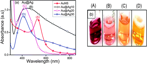
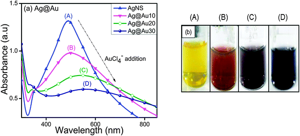
The characteristic surface plasmon (SP) band of AuNSs (529 nm) blue-shifted to a broad peak at 447 nm and 419 nm of increased intensity upon addition of Ag+ ions (10–20 μl, Fig. 1a) accompanied by the color change from wine red to pink to orange as seen in Fig. 1b. This indicated some morphological changes in which AuNSs were used as seeds for the controlled reduction of Ag+ and thereby deposition of the Ag-shell over the Au-core as observed from the absorbance measurements. With the progressive addition of Ag+ ions (30 μl), a sharp yellow color absorption band corresponding to 408 nm appeared. At this point, the incident light could only penetrate the Ag shell of a certain thickness and could not reach Au cores to excite their electrons.27 Therefore, it is presumed that AuNSs are completely covered by Ag giving rise to Aucore–Agshell (Au@Ag) NCs of different shell thicknesses. These results are in good conformity with the reported blue shifting of the SP band for AuNS from 520 nm to 438 nm and 402 nm with increasing Ag-shell thickness.30In contrast to AuNSs, the SP band of AgNSs (414 nm) decreased gradually and became broader with a peak position shifting to longer wavelengths, 490 nm to 508 nm and 550 nm, through the increasing addition of HAuCl4− ion aqueous solution (Fig. 2a). This observation is consistent with the report where the formation of hollow Ag–Au NCs takes place via replacement of Ag by Au.34 Due to the progressive galvanic replacement reaction, Au is deposited on the NP surface and the cavity size in hollow particles increases with reaction resulting in a red-shift35 in the SP band of hollow Ag–Au NCs. This morphological transformation was further evidenced by the color change from yellow to light orange to purple and blue as shown in Fig. 2b. The above experiment was repeated with AuNSs and AgNSs of different sizes as observed from their SP band in Fig. S1 in the ESI† and almost similar results were obtained. In Fig. S1a (ESI†), the SP band of AuNSs (518 nm) blue-shifted to a broad peak at 460 nm, whereas that of AgNSs (414 nm) red-shifted to a broadened peak at 606 nm after treatment with Ag+ and HAuCl4− (20 μl, 0.01 M), respectively. The absorbance peaks of AuNSs (528 nm) and AgNSs (400 nm) became sharp at 420 nm and 558 nm after coating with a higher amount of Ag+ and HAuCl4− (30 μl, 0.01 M), respectively, as shown in ESI,† Fig. S1b.
3.2. Electro-kinetic parameters
When NPs are dispersed in an aqueous solution, there is adsorption or surface ionization of cations or anions, which results in the formation of an electrical double layer leading to the development of new surface charge measured by the zeta potential (ζ). Here, the measured zeta potential of unwashed citrate-capped AuNSs (−22.5 mV) and AgNSs (−28.79 mV) was found to be negatively charged probably due to the presence of surface adsorbed and free citrate ions in their aqueous suspension. However, after washing with de-ionized water, the zeta potential of bare AuNSs (−6.13 mV) and AgNSs (−5.74 mV) was notably reduced (Fig. 3).36 The citrate-capped AuNS and AgNS are probably stabilized through steric repulsions as reported37–40 due to the presence of coordinated/adsorbed citrates along with dangling citrate species, which are not in direct contact with the metal surface of Au or Ag NPs. As a result, intermolecular interactions take place between the absorbed citrate and dangling citrate anions by COOH hydrogen bonds and hence form citrate multilayers on the NP surface. This provides steric repulsion37 between citrate layers present on the adjacent NPs, and helps in NP dispersion stability in solution.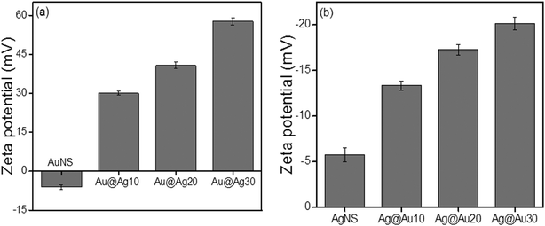 | ||
| Fig. 3 Electro-kinetic parameters of (a) Au nanospheres and (b) Ag nanospheres after deposition of 0.01 M AgNO3 and 0.01 M HAuCl4·3H2O (10–30 μl), respectively. | ||
The zeta potential for bimetallic Au@Ag and Ag@Au NCs was measured in their aqueous medium having core![[thin space (1/6-em)]](https://www.rsc.org/images/entities/char_2009.gif) :
:![[thin space (1/6-em)]](https://www.rsc.org/images/entities/char_2009.gif) shell atomic ratios of 1
shell atomic ratios of 1![[thin space (1/6-em)]](https://www.rsc.org/images/entities/char_2009.gif) :
:![[thin space (1/6-em)]](https://www.rsc.org/images/entities/char_2009.gif) 0.2, 1
0.2, 1![[thin space (1/6-em)]](https://www.rsc.org/images/entities/char_2009.gif) :
:![[thin space (1/6-em)]](https://www.rsc.org/images/entities/char_2009.gif) 0.5, and 1
0.5, and 1![[thin space (1/6-em)]](https://www.rsc.org/images/entities/char_2009.gif) :
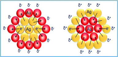
:![[thin space (1/6-em)]](https://www.rsc.org/images/entities/char_2009.gif) 0.7 as calculated in ESI,† Tables S2 and S3. The Ag+ deposition on the AuNS surface led to the positive (+30.3 mV) surface charge indicating that the bare AuNSs are chemically modified through the absorbed charged Ag-shell as shown in Fig. 3a. Further, it was observed that the zeta potential became more positive (+40.7 mV to +57.8 mV), probably due to the increasing Ag-shell thickness with gradual addition of Ag+. In the case of AgNSs, the surface charge became more negative36 (−13.35 mV to −20.13 mV) after progressive addition of HAuCl4− as shown in Fig. 3b. This charge alteration might be due to the electron charge donation from Ag with low ionization potential (7.58 eV) to Au with high ionization potential (9.22 eV)41–43 as depicted in Scheme 1. This results in accumulation of the positive charge on the Ag-shell and the negative charge on the Au-shell in the case of Au@Ag and Ag@Au NCs, respectively, as evidenced by the above results in agreement with the previous report.43
0.7 as calculated in ESI,† Tables S2 and S3. The Ag+ deposition on the AuNS surface led to the positive (+30.3 mV) surface charge indicating that the bare AuNSs are chemically modified through the absorbed charged Ag-shell as shown in Fig. 3a. Further, it was observed that the zeta potential became more positive (+40.7 mV to +57.8 mV), probably due to the increasing Ag-shell thickness with gradual addition of Ag+. In the case of AgNSs, the surface charge became more negative36 (−13.35 mV to −20.13 mV) after progressive addition of HAuCl4− as shown in Fig. 3b. This charge alteration might be due to the electron charge donation from Ag with low ionization potential (7.58 eV) to Au with high ionization potential (9.22 eV)41–43 as depicted in Scheme 1. This results in accumulation of the positive charge on the Ag-shell and the negative charge on the Au-shell in the case of Au@Ag and Ag@Au NCs, respectively, as evidenced by the above results in agreement with the previous report.43
3.3. Particle size distribution
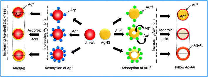
The coating or deposition of the second metal (shell) on core NPs may lead to the change in the particle size of bare NPs. Here, the Au-core of particular size (25 nm) was used for the deposition of an Ag layer of varying thicknesses as a function of concentration of Ag+ ions. The Ag+ ions are first adsorbed on the surface of AuNSs, which then undergo reduction in the presence of a weak reducing agent, ascorbic acid, so that the reduction takes place on the surface of existing metallic surfaces. Subsequently, the resultant NCs may lead to the increment of size compared to bare NPs (Scheme 2) due to the growing thickness of the Ag-shell irrespective of the Au-core size which can be evidenced by the DLS particle size distribution.44 It revealed that the average hydrodynamic diameter of AuNSs (25 nm) upon addition of Ag+ exhibited an increase in particle diameter (31 nm) signifying the successful coating of the Ag layer on AuNSs as shown in Fig. 4a. Further, the successive addition of Ag+ into AuNSs resulted in a progressive increase in particle diameter (41 nm to 62 nm) indicating the Ag-shell growth of higher thickness depending upon its added concentration. Similarly, Fig. 4b shows that the average hydrodynamic diameter of AgNSs (21 nm) subsequently, upon addition of different amounts of HAuCl4−, led to the gradual increase in particle diameter (33 nm to 58 nm). The AgNS acts as a sacrificial template for the growth of the Au layer and resulted in the formation of hollow Ag–Au alloys of increased cavity size due to the galvanic displacement reaction as depicted in Scheme 2. The observed hydrodynamic diameter is found to be greater than the TEM size due to the presence of the hydration layer while estimating the size by DLS. The DLS autocorrelation functions and their corresponding fits are demonstrated in the ESI† (Fig. S4–S6).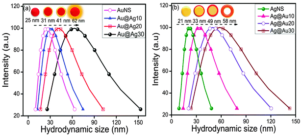 | ||
| Fig. 4 DLS particle size distribution after deposition of 10–30 μl (0.01 M) (a) AgNO3 over Au nanospheres and (b) HAuCl4·3H2O over Ag nanospheres. | ||
3.4. Morphological studies
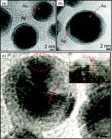
TEM analysis revealed that the bare AuNS of diameter 10–16 nm (Fig. 5a) served as seeds for Ag growth on its surface. The gradual addition of Ag+ on pre-synthesized AuNSs led to a coating of an Ag layer of thickness ∼3–4 nm as shown in Fig. 5b and c. This is in good agreement with the structural configuration of the core–shell, i.e., Au@Ag NCs where the dark core is attributed to Au and the light shell corresponds to Ag. The Ag shell was observed to become thicker (∼8–10 nm), diffused and non-uniform with the addition of a higher amount of Ag+ ions giving rise to irregular shape (diameter ∼ 20 nm) as seen in Fig. 5d. These observations are in accordance with the reports where Ag coating becomes anisotropic with increasing thickness of the Ag shell and the shape of Au nanorods approached being a non-regular.14,45 Elemental analysis further confirmed that both Au and Ag are present in Au@Ag NCs as shown in EDS spectra, ESI,† Fig. S7a. The HRTEM images of the as-prepared Au@Ag NCs of size ∼14–19 nm with a thickness of the Ag shell ∼2–3 nm are shown in Fig. 6a and b. The measured fringe spacings are 2.3 Å and 1.4 Å, which corresponded well with the (111) plane of the FCC Au (2.355 Å, Fig. 6c) and the (110) plane of Ag (1.44 Å, JCPDS card no. 04-07484, the inset of Fig. 6c), respectively. Similarly, another HRTEM and the SAED pattern (ESI,† Fig. S8) of the Au@Ag NCs confirmed the planes (110) of Ag and (111) of Au NPs. These results indicated the presence of both Au and Ag supporting the formation of the Au core with the Ag shell as suggested by the previous report.46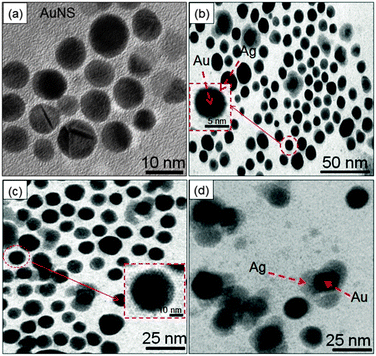 | ||
| Fig. 5 TEM images of (a) Au nanospheres and (b–d) Au@Ag core–shell nanocomposites of varying Ag-shell thicknesses (ca. ∼3–10 nm). | ||
On the other hand, the different morphology of AgNSs was observed via the galvanic displacement reaction between AgNSs and HAuCl4− as seen in Fig. 7. The bare AgNS (diameter = 10–11 nm, Fig. 7a) was uniformly coated with an Au-layer (thickness = ∼2.9 nm) upon treatment with a lower amount (10 μl) of HAuCl4− as noted in Fig. 7b. With increasing Au content, the Ag particles are oxidized into Ag+ ions due to the higher reduction potential of Au+3/Au (0.99 V) than Ag+/Ag (0.80 V). As a result, the growth of the Au layer on the surface of the Ag template takes place leading to the formation of Ag–Au alloys (Fig. 7c) of diameter ∼10–12 nm. The difference in the rates of diffusion of Ag atoms outward and that of AuCl4− ions inward started the formation of hollow spaces (∼5 nm) to produce Ag–Au alloy nanorings (diameter = 13–15 nm, Fig. 7d) with increased cavity size as reported by many groups10,35,47 in which different shapes (cubes, spheres, wires, etc.) of Ag–Au bimetallic NCs are prepared. The resulting hollow NCs were observed to be composed of both metals as evidenced by the presence of Ag and Au in EDS analysis (ESI,† Fig. S7b). Further, the SAED pattern supported the existence of the planes (111) of Au and (110) of Ag particles as depicted in Fig. 7e.48
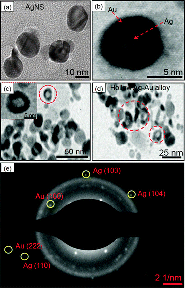 | ||
| Fig. 7 TEM images of (a) Ag nanospheres, (b–d) Ag@Au core–shell nanocomposites obtained by deposition of 10–30 μl of HAuCl4·3H2O (0.01 M), and (e) SAED patterns obtained from image (c). | ||
3.5. Catalytic activity
The absorption spectra for the reduction of NB (270 nm) to aniline (AN) by NaBH4 exhibited insignificant changes in the absence of AuNS up to 120 min as shown in ESI,† Fig. S9a. However, with the addition of AuNSs (size = 10–16 nm), the reaction rate was accelerated and the absorption band intensity corresponding to NB at 270 nm was gradually reduced with the simultaneous evolution of a new absorption band at 234 nm, characteristic of the AN formation (Fig. 8a). The time course studies (Fig. 8b) displayed that the Au@Ag and hollow Ag–Au alloy NCs exhibited higher yields of AN i.e., 50% and 72%, respectively, within 15–30 min as compared to bare AuNSs (42%) and AgNSs (20%) within 40–50 min. The superior catalytic activity of bimetallic NCs can be explained due to the modification of the electronic structures2,49,50 in two metals, which results in broader d-bands shifted towards the Fermi-level due to the charge rearrangement. This is in agreement with the report51 where the polyelectrolyte multilayer supported Au@Ag (k = 0.18 min−1) NCs showed higher catalytic activity for the reduction of p-nitrophenol to p-aminophenol by NaBH4 than the corresponding monometallic AuNS (k = 0.019 min−1) and AgNS (k = 0.069 min−1) due to the synergistic effect. The bimetallic synergistic effect exhibits a dramatic improvement in catalytic activity and selectivity in contrast to monometallic counterparts.3,45 The introduction of the second metal (shell) over the surface of another metal NP core leads to the structural change and formation of boundaries of two metal atoms. Consequently, electronic charge transfer occurs between two metals leading to a change in the electron density on the resultant bimetallic NP, which may promote the reduction process more efficiently.41,42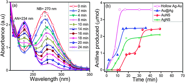 | ||
| Fig. 8 Changes in absorption spectra during nitrobenzene reduction by (a) Au nanospheres (size ∼10–16 nm) and (b) a time course graph of aniline formation by various mono/bimetallic nanostructures. | ||
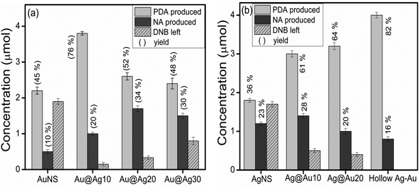
The effect of the electron withdrawing group on the rate of reduction was studied by carrying out the reduction of 1,3-DNB to 3-nitroaniline (NA) and phenylenediamine (PDA) by core–shell NCs of varying shell-thicknesses. The reduction process led to the decrease in absorption spectra of DNB (240 nm) with the progressive rise of a peak at 285 nm corresponding to PDA (ESI,† Fig. S9b). But the quantitative analysis (HPLC, ESI,† Fig. S10 and S11) revealed the formation of another product also i.e., NA along with PDA. Fig. 9a shows that the yield of PDA was increased to 70% with addition of Ag+ (10 μl) to AuNSs (Au@Ag10) in contrast to monometallic AuNSs (45%). However, a further increase in the Ag amount (20 and 30 μl) on the Au-core i.e., Au@Ag20 (PDA = 52%) and Au@Ag30 NCs (PDA = 48%), respectively, dramatically decreased the catalytic activity. This can be ascribed to the weaker electronic effect between the distant Au-core and the Ag-shell, resulting from growing Ag-shell thickness. Ataee-Esfahani et al.52 even reported that the Pt surface cannot work well as an electro-active surface for methanol oxidation with a higher Pt/Au molar ratio or without an Au core. On the other hand, the catalytic reduction by AgNSs to the growing amount of HAuCl4− (10–130 μl) showed a progressive increase in PDA yield as seen in Fig. 9b. The hollow Ag–Au alloy (PDA = 82%) exhibited highest catalytic activity among the various Ag@Au core–shell NCs (PDA = 61–64%) and bare AgNSs (PDA = 36%) due to their increased surface areas and reduced densities. In this, the inner surface of the hollow shell may provide more bonding sites for the chemical reaction.53–56 In addition, the different arrangement of Ag and Au in the catalysts (either as a core or a shell) also played a role in affecting the catalytic efficiency due to which Ag@Au NCs exhibited better catalytic activity than Au@Ag NCs.38 This is because the electronic charge could transfer from the Ag-core to the Au-shell in view of their ionization potential, leading to an increase in electron density on directly exposed Au NP surface to the solution promoting the reduction more efficiently as reported earlier.42,50 Further, GC-MS analysis of the reaction product obtained after reduction of DNB with NCs qualitatively evidences the formation of PDA, Rt = 11.4 and 12.1 min (1 and 2) and NA, Rt = 14.6 and 15.3 min (4 and 6) from DNB, Rt = 14.0 and 14.7 min (3 and 5) as noted in Fig. 10a and b and ESI,† Fig. S12. The mass spectrum (Fig. 10c–h) showed the peak at m = 108 for 1 and 2 and m = 138 for 4 and 6 compounds confirming the PDA and NA formation. The other peak at m = 168 for 3 and 5 compounds corresponding to DNB was also observed due to its incomplete conversion. Among DNB and NB, the higher reduction rate was found in DNB probably due to the reason that the insertion of the second –NO2 group (the e− withdrawing group) into nitrobenzene might lower the electron density on the other –NO2 group favoring rapid conversion of –NO2 into the –NH2 group. Hence, the conversion of nitro-aromatic compounds to their respective products was enhanced by ∼2 times using bimetallic NCs in contrast to their monometallic counterparts. Therefore, through the optimization of shell-thickness and nature of the core, the catalytic efficiency can be enhanced for the other reduction processes.
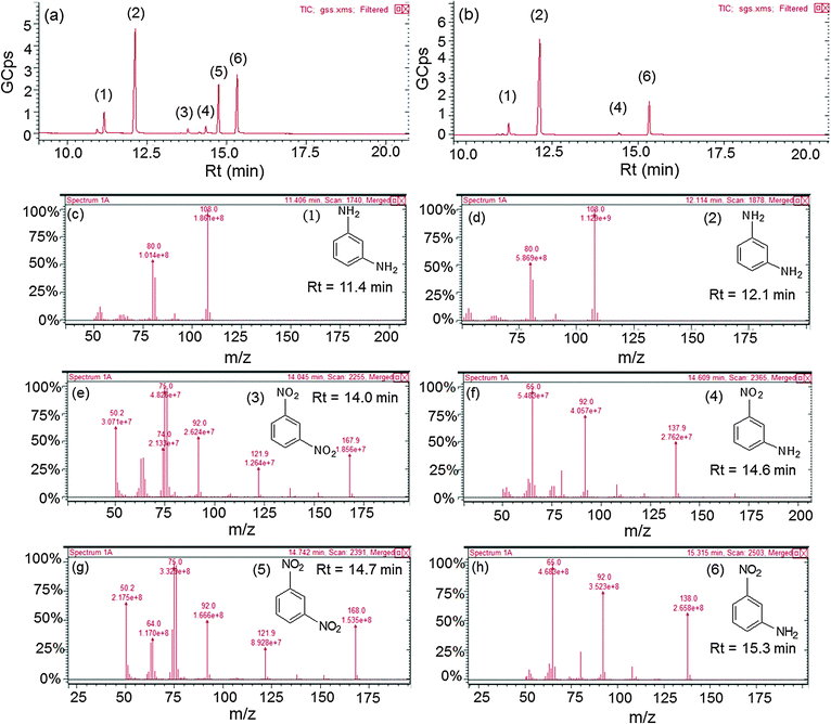 | ||
| Fig. 10 Gas chromatograph of the reaction product after reduction of 1,3-dinitrobenzene by (a) Au@Ag core–shell nanocomposites, (b) hollow Au–Ag alloys, and (c–h) their corresponding mass spectra. | ||
4. Conclusions
In summary, the effects of the nature of coinage metal cores as well as shell-thicknesses have been studied on the variation of surface electro-kinetic and catalytic properties as compared to their monometallic counterparts. The Ag shell (or Au) thicknesses on Au (or Ag) cores can be easily tuned by controlling the concentration of starting precursor solutions. As a result, the synergistic effect of mixed band energy of two different coinage metals, active catalytic active sites and preferred surface orientation for adsorption of reacting substrates may alter catalytic efficiency. These bimetallic nanocolloids of coinage metals are used for improving the catalytic activity for nitro-organics reduction reaction where the selectivity and yield of the products can be tuned depending on their composition and surface morphology.Acknowledgements
We acknowledge Dr B. N. Chudasama (School of Physics and Material Science, Thapar University) for the zeta potential and DLS measurement. We would also like to thank the Sophisticated Analytical Instrumentation Facility (IIT Bombay) for TEM analysis and NIPER, Mohali (India), for HRTEM analysis. We acknowledge CSIR for the financial support.Notes and references
- N. Toshima and T. Yonezawa, New J. Chem., 1998, 22, 1179–1201 RSC.
- D. S. Wang and Y. D. Li, Adv. Mater., 2011, 23, 1044–1060 CrossRef CAS PubMed.
- H. L. Jiang and Q. Xu, J. Mater. Chem., 2011, 21, 13705–13725 RSC.
- R. Ferrando, J. Jellinek and R. L. Johnston, Chem. Rev., 2008, 108, 845–910 CrossRef CAS PubMed.
- F. Tao, Chem. Soc. Rev., 2012, 41, 7977–7979 RSC.
- C. C. Tyson, A. Bzowski, P. Kristof, M. Kuhn, R. Sammynaiken and T. K. Sham, Phys. Rev. B: Condens. Matter Mater. Phys., 1992, 45, 8924–8928 CrossRef CAS.
- S. Nishimura, A. T. N. Dao, D. Mott, K. Ebitani and S. Maenosono, J. Phys. Chem. C, 2012, 116, 4511–4516 CAS.
- S. Sakong, C. Mosch and A. Gross, Phys. Chem. Chem. Phys., 2007, 9, 2216–2225 RSC.
- M. Kaushik, M. Mandal, N. Pradhan and T. Pal, Nano Lett., 2001, 1, 319–322 CrossRef.
- Y. Sun and Y. Xia, J. Am. Chem. Soc., 2004, 126, 3892–3901 CrossRef CAS PubMed.
- B. Rodriguez-Gonzalez, A. Burrows, M. Watanabe, C. J. Kiely and L. M. L. Marzan, J. Mater. Chem., 2005, 15, 1755–1759 RSC.
- M. Tsuji, N. Miyamae, S. Lim, K. Kimura, X. Zhang, S. Hikino and M. Nishio, Cryst. Growth Des., 2006, 6, 1801–1807 CAS.
- M. Liu and P. Guyot-Sionnest, J. Phys. Chem. B, 2004, 108, 5882–5888 CrossRef CAS.
- Y. Xiang, X. Wu, D. Liu, Z. Li, W. Chu, L. Feng, K. Zhang, W. Zhou and S. Xie, Langmuir, 2008, 24, 3465–3470 CrossRef CAS PubMed.
- M. J. Alam and M. Tsuji, CrystEngComm, 2011, 13, 6499–6506 RSC.
- M. Tsuji, N. Nakamura, M. Ogino, K. Ikedo and M. Matsunaga, CrystEngComm, 2012, 14, 7639–7647 RSC.
- M. P. Mallin and C. J. Murphy, Nano Lett., 2002, 2, 1235–1237 CrossRef CAS.
- L. Rivas, S. Sanchez-Cortes, J. V. Garcia-Ramos and G. Morcillo, Langmuir, 2000, 16, 9722–9728 CrossRef CAS.
- L. Chen, L. Kuai and B. Geng, CrystEngComm, 2013, 15, 2133–2136 RSC.
- C. W. Yang, K. Chanda, P. H. Lin, Y. N. Wang, C. W. Liao and M. H. Huang, J. Am. Chem. Soc., 2011, 133, 19993–20000 CrossRef CAS PubMed.
- M. Sakamoto, T. Tachikawa, M. Fujitsuka and T. Majima, Adv. Funct. Mater., 2007, 17, 857–862 CrossRef CAS.
- T. Nakamura, Y. Tsukahara, T. Yamauchi, T. Sakata, H. Mori and Y. Wada, Chem. Lett., 2007, 36, 154–155 CrossRef CAS.
- M. Tsuji, S. Hikino, R. Tanabe, M. Matsunaga and Y. Sano, CrystEngComm, 2010, 12, 3900–3908 RSC.
- Y. Ding, F. Fan, Z. Tian and Z. L. Wang, J. Am. Chem. Soc., 2010, 132, 12480–12486 CrossRef CAS PubMed.
- J. Xu, A. R. Wilson, A. R. Rathmell, J. Howe, M. Chi and B. J. Wiley, ACS Nano, 2011, 5, 6119–6127 CrossRef CAS PubMed.
- S. Chen, S. V. Jenkins, J. Tao, Y. Zhu and J. Chen, J. Phys. Chem. C, 2013, 117, 8924–8932 CAS.
- Y. Ma, W. Li, E. C. Cho, Z. Li, T. Yu, J. Zeng, Z. Xie and Y. Xia, ACS Nano, 2010, 4, 6725–6734 CrossRef CAS PubMed.
- M. Tsuji, R. Matsuo, P. Jiang, N. Miyamae, D. Ueyama, M. Nishio, S. Hikino, H. Kumagae, K. S. N. Kamarudin and X. L. Tang, Cryst. Growth Des., 2008, 8, 2528–2536 CAS.
- M. Tsuji, M. Ogino, M. Matsunaga, N. Miyamae, R. Matsuo, M. Nishio and M. J. Alam, Cryst. Growth Des., 2010, 10, 4085–4090 CAS.
- S. Pande, S. K. Ghosh, S. Praharaj, S. Panigrahi, S. Basu, S. Jana, A. Pal, T. Tsukuda and T. Pal, J. Phys. Chem. C, 2007, 111, 10806–10813 CAS.
- N. G. Bastus, J. Comenge and V. Puntes, Langmuir, 2011, 27, 11098–11105 CrossRef CAS PubMed.
- G. Kawamura, Y. Yang and M. Nogami, J. Phys. Chem. C, 2008, 112, 10632–10636 CAS.
- I. Ojea-Jimenez and V. Puntes, J. Am. Chem. Soc., 2009, 131, 13320–13327 CrossRef CAS PubMed.
- X. Zhang, G. Zhang, B. Zhang and Z. Su, Langmuir, 2013, 29, 6722–6727 CrossRef CAS PubMed.
- C. Shankar, A. T. N. Dao, P. Singh, K. Higashimine, D. M. Mott and S. Maenosono, Nanotechnology, 2012, 23, 245704 CrossRef PubMed.
- S. H. Wang, C. W. Lee, A. Chiou and P. K. Wei1, J. Nanobiotechnol., 2010, 8, 33–45 CrossRef CAS PubMed.
- J. W. Park and J. S. S. Parry, J. Am. Chem. Soc., 2014, 136, 1907–1921 CrossRef CAS PubMed.
- S. Biggs, P. Mulvaney, C. F. Zukoski and F. Grieser, J. Am. Chem. Soc., 1994, 116, 9150–9157 CrossRef CAS.
- P. Wagener, A. Schwenke and S. Barcikowski, Langmuir, 2012, 28, 6132–6140 CrossRef CAS PubMed.
- C. H. Munro, W. E. Smith, M. Garner, J. Clarkson and P. C. White, Langmuir, 1995, 11, 3712–3720 CrossRef CAS.
- H. Zhanga and N. Toshima, Catal. Sci. Technol., 2013, 3, 268–278 Search PubMed.
- S. Tokonami, N. Morita, K. Takasaki and N. Toshima, J. Phys. Chem. C, 2010, 114, 10336–10341 CAS.
- S. Nishimura, A. T. N. Dao, D. Mott, K. Ebitani and S. Maenosono, J. Phys. Chem. C, 2012, 116, 4511–4516 CAS.
- M. Kahraman, O. Aydın and M. Culha, Plasmonics, 2009, 4, 293–301 CrossRef CAS.
- Q. Fu, D. G. Zhang, M. F. Yi, X. X. Wang, Y. K. Chen, P. Wang and H. Ming, J. Opt., 2012, 14, 085001 CrossRef.
- H. F. Zarick, W. R. Erwin, J. Aufrecht, A. Coppola, B. R. Rogers, C. L. Pint and R. Bardhan, J. Mater. Chem. A, 2014, 2, 7088–7098 CAS.
- S. W. Hsu, K. On, B. Gao and A. R. Tao, Langmuir, 2011, 27, 8494–8499 CrossRef CAS PubMed.
- T. Ghosh, B. Satpati and D. Senapati, J. Mater. Chem. C, 2014, 2, 2439–2447 RSC.
- P. Venkatesan and J. Santhanalakshmi, Langmuir, 2010, 26, 12225–12229 CrossRef CAS PubMed.
- X. Guo, Q. Zhang, Y. Sun, Q. Zhao and J. Yang, ACS Nano, 2012, 6, 1165–1175 CrossRef CAS PubMed.
- X. Zhang and Z. Su, Adv. Mater., 2012, 24, 4574–4577 CrossRef CAS PubMed.
- H. Ataee-Esfahani, L. Wang, Y. Nemoto and Y. Yamauchi, Chem. Mater., 2010, 22, 6310–6318 CrossRef CAS.
- H. Wu, P. Wang, H. He and Y. Jin, Nano Res., 2012, 5, 135–144 CrossRef CAS PubMed.
- M. R. Kim, D. K. Lee and D. J. Jang, Appl. Catal., B, 2011, 103, 253–260 CrossRef CAS PubMed.
- H. M. Chen, R. S. Liu, M. Y. Lo, S. C. Chang, L. D. Tsai, Y. M. Peng and J. F. Lee, J. Phys. Chem. C, 2008, 112, 7522–7526 CAS.
- J. Zeng, Q. Zhang, J. Chen and Y. Xia, Nano Lett., 2010, 10, 30–35 CrossRef CAS PubMed.
Footnote |
| † Electronic supplementary information (ESI) available: UV-vis absorption spectra, EDS spectra, HRTEM and SAED patterns of Au@Ag and Ag@Au NCs, calculation of the atomic ratio of Au/Ag, autocorrelation spectra for DLS particle size distribution, and UV-vis absorption spectra, HPLC and GC analysis for the reduction of NB and 1,3-DNB. See DOI: 10.1039/c4nj01419g |
| This journal is © The Royal Society of Chemistry and the Centre National de la Recherche Scientifique 2015 |

