DOI:
10.1039/C4NJ01346H
(Paper)
New J. Chem., 2015,
39, 279-286
Assembly of a CdS quantum dot–TiO2 nanobelt heterostructure for photocatalytic application: towards an efficient visible light photocatalyst via facile surface charge tuning†
Received
(in Montpellier, France)
10th August 2014
, Accepted 1st October 2014
First published on 3rd October 2014
Abstract
In recent years increasing efforts have been devoted to synthesizing hybrid semiconductor nanocomposites; however, it still poses a challenge to fabricate well-defined semiconductor based heterostructures. In this work, a well-defined TiO2 nanobelt functionalized with a CdS quantum dot (viz. TiO2 NB–CdS QD) binary nanostructure has been fabricated by an efficient self-assembly approach based on a facile surface charge tuning. A collection of techniques including X-ray diffraction (XRD), UV-vis diffuse reflectance spectra (DRS), field emission scanning electron microscopy (FESEM), transmission scanning electron microscopy (TEM), and X-ray photoelectron spectra (XPS) was utilized to characterize the structure of TiO2 NB–CdS QD binary heterostructure. It was found that the as-constructed TiO2 NB–CdS QD heterostructure exhibits significantly enhanced photocatalytic performance for the degradation of organic pollutants under visible light irradiation in comparison with blank TiO2 NBs and randomly mixed counterparts. The significantly enhanced photocatalytic performance of the TiO2 NB–CdS QD heterostructure can be attributed to the synergistic contribution from the enhanced light absorption intensity of the hybrid nanocomposite and intimate interfacial contact between CdS QD and TiO2 NB ingredients afforded by the electrostatic self-assembly buildup, which remarkably facilitates charge separation and lengthens the lifetime of photogenerated electron–hole pairs under visible light irradiation. Moreover, it was demonstrated that the TiO2 NB–CdS QD heterostructure shows favorable photostability on account of intrinsic protection by a surface ligand of CdS QDs. In addition, the possible photocatalytic mechanism was tentatively proposed and predominant active species during the photocatalytic process were unambiguously determined.
1. Introduction
In recent years, tremendous efforts have been devoted to exploring one-dimensional (1D) semiconductor nanostructures, such as nanorods, nanowires, and nanotubes for extensive applications in a myriad of processes, such as environmental remediation, solar energy conversion, photodetection, and photocatalysis.1–7 In particular, TiO2 nanobelts (TiO2 NBs) grown directly on a conducting substrate (e.g. Ti foil) have garnered the most research attention due to their large specific surface area, enhanced light absorption and scattering, as well as fast and long-distance electron transport.8 However, the photocatalytic activity of TiO2 NBs is generally retarded by the limited active surface sites, fast recombination of photogenerated electron–hole pairs, and limited light absorption merely confined within the UV region.9 Therefore, research on the fabrication of well-defined TiO2 NB-based heterojunction nanocomposites with a favorable band gap and a low lattice mismatch has been far from satisfactory.
To date, it has been well-established that photoactivities of the TiO2 NB-based heterojunction nanostructure can be improved by depositing metal nanoparticles (Ag, Au, or Pd),10–12 doping with metallic or non-metallic elements,13,14 or combining with a secondary semiconductor (e.g. Co3O4, CdS, MoS2, Ag2O, and ZnO).15–19 Among them, the modification of TiO2 NBs with narrow band semiconductors has been regarded as the most efficient route for light harvesting. CdS, as a quintessential visible-light-responsive photocatalyst, has been extensively studied owing to its intrinsic suitable bandgap (2.4 eV) which agrees well with the spectrum of sunlight.15 Particularly, CdS quantum dots (QDs) with a size-dependent band gap, large oscillator strengths, and high cross-sections for multi-photon absorption demonstrate much more promising photocatalytic performances as compared with bulk counterparts.20
Thus far, CdS QD–TiO2 hybrid nanostructures have been overwhelmingly investigated owing to the matched energy level between CdS and TiO2 by forming the type II band configuration,21–31e.g. CdS QD–TiO2 nanotube array heterostructures have been prepared for multi-functional photocatalytic applications,22 and CdS QD-sensitized single-crystalline rutile TiO2 nanorod arrays or TiO2 nanospheroidal electrodes were fabricated using the chemical bath deposition technique for photoelectrochemical and solar cell applications.23,26 Despite these advances, it should be noted that most of the previous studies are mainly confined to conventional 1D TiO2 nanotubes or nanorods as building blocks; the report on the 1D TiO2 nanobelts grown on the Ti foil is relatively scarcely reported. Moreover, so far, there has been no report on the fabrication of the hierarchical CdS QD sensitized TiO2 nanobelt (TiO2 NB–CdS QD) hybrid nanostructure through a facile surface charge tuning and systematic investigation on its great potential as an efficient visible-light-driven photocatalyst.
Herein, we have fabricated a well-defined TiO2 NB–CdS QD heterostructure based on intimate interfacial interaction between 1D TiO2 NBs and CdS QDs afforded by the electrostatic self-assembly buildup, and the photocatalytic performance of the as-assembled hybrid heterostructure was systematically probed. It was found that the TiO2 NB–CdS QD heterostructure exhibits significantly enhanced visible-light-driven photoactivity and favorable photostability as compared with blank TiO2 NBs and randomly mixed counterparts. Photoelectrochemical results ascertained the remarkably improved separation efficiency and prolonged lifespan of photoexcited electron–hole charge carriers over the TiO2 NB–CdS QD heterostructure. In addition, the photocatalytic mechanism was also presented and predominant active species responsible for the significantly enhanced photocatalytic performances were ascertained. It is expected that our work could open up a new paradigm for the fabrication of various narrow-band-gap semiconductor/1D semiconductor heterostructures for extensive photocatalytic applications.
2. Experimental section
2.1 Materials
Titanium sheets (50 mm × 20 mm × 0.1 mm, 99.9%), thioglycolic acid (C2H4O2S, TGA), cadmium chloride (CdCl2·2.5H2O), sodium sulfide (Na2S·9H2O), sodium hydroxide (NaOH), acetone (C3H6O), ethanol (C2H6O), 3-aminopropyl-trimethoxysilane (C9H23NO3Si, APTES), silver nitrate (AgNO3), ammonium oxalate (N2H8C2O4), benzoquinone (C6H4O2), isopropanol (C3H8O) were obtained from Sinopharm Chemical Reagent Co., Ltd (Shanghai, China). Deionized water (DI H2O, Millipore, 18.2 MΩ cm resistivity). All materials and chemicals were used as received without further purification.
2.2 Synthesis of TiO2 NBs
The preparation of TiO2 NBs on the Ti foil was referred to previous work with slight modification.32 Firstly, the Ti foil was cut into small pieces (10 mm × 40 mm) and ultrasonicated in acetone, ethanol, and DI H2O for 10 min, respectively. Subsequently, the Ti foils were dipped into 40 mL of 5 M NaOH aqueous solution in a 50 mL Teflon-lined autoclave which was kept at 200 °C for 24 h. After cooling down naturally to the room temperature, the samples were washed with DI H2O several times and dried in a dry cabinet. Finally, the samples were immersed in 1 M HCl aqueous solution for 1 h to replace Na+ with H+, and annealed at 450 °C in air for 1 h in an electronic furnace.
2.3 Preparation of TGA-capped CdS QDs (CdS@TGA)
CdS QDs were synthesized according to the previous report.22 Briefly, 250 μL of TGA was added into 50 mL of CdCl2 (1.0 × 10⁻² M) aqueous solution and N2 was bubbled throughout the solution for 30 min to remove O2 at 110 °C. During this period, 1.0 M NaOH aqueous solution was added dropwise to adjust the solution pH to 11. Then, 5.5 mL of 0.1 M Na2S aqueous solution was rapidly injected to the above solution and the mixture was continuously refluxed under a N2 atmosphere for 4 h. Finally, the as-obtained TGA-stabilized CdS QDs were stored in a refrigerator at 4 °C for further use.
2.4 Self-assembly of the TiO2 NB–CdS QD heterostructure
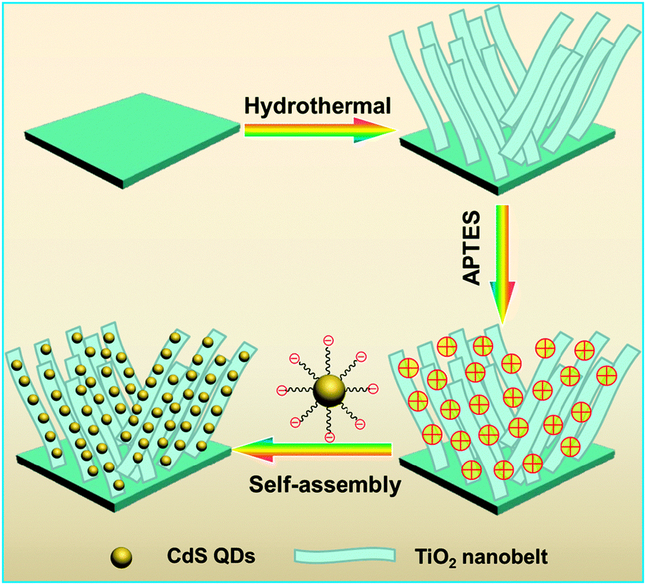
The as-prepared TiO2 NBs were dipped into 50 mL of ethanol containing APTES (1 mL) ultrasonicated for 30 min, and refluxed for 4 h at 60 °C. Afterward, the APTES-treated TiO2 NBs were rinsed completely with ethanol to wash away the remaining APTES moieties. Note that the pKa of APTES is ca. 11 which is close to the pH value of CdS QD aqueous solution; however, the TiO2 NBs synthesized in our work were subjected to strong acid treatment (1 M HCl), thus, the TiO2 NB substrate could provide a pronounced acid environment which is full of H+ absorbed on the surface. In this way, APTES moieties would be protonated when grafted onto the TiO2 NB framework leading to the positively charged surface (–NH3+). Subsequently, the thus-obtained positively charged amine-functionalized TiO2 NBs were immersed into the CdS QDs@TGA aqueous solution for 2 h which produced the TiO2 NB–CdS QD heterostructure. For comparison, the TiO2 NB–CdS QD nanocomposite obtained by directly mixing TiO2 NBs with CdS QDs without surface modification was also prepared under analogous experimental conditions. The process for the preparation of the TiO2 NB–CdS QD heterostructure is vividly depicted in Scheme 1. A pure CdS QD film was prepared by dipping the APTES-modified Ti foil into the same CdS QD aqueous solution with the same dipping time.
 |
| | Scheme 1 Schematic flowchart of the self-assembly of the TiO2 NB–CdS QD heterostructure. | |
2.5 Characterization
The crystal phase properties of the samples were analyzed using a Bruker D8 Advance X-ray diffractometer (XRD) under Ni-filtered Co Kα radiation at 40 kV and 40 mA at a scan rate of 0.02° per second. Field-emission scanning electron microscopy (FESEM) was used to determine the morphology of the samples on a FEI Nova NANOSEM 230 spectrophotometer. Transmission electron microscopy (TEM) and high-resolution transmission electron microscopy (HRTEM) images were obtained using a JEOL model JEM 2010 EX instrument at an accelerating voltage of 200 kV. X-ray photoelectron spectroscopy (XPS) measurements were performed using a Thermo Scientific ESCALAB250 spectrometer; binding energy (BE) of the element was calibrated to BE of C 1s (284.59 eV). The optical properties of the samples were characterized using a Cary 500 UV-visible ultraviolet/visible diffuse reflectance spectrophotometer (DRS), in which BaSO4 was employed as the internal reflectance standard. The electrochemical analysis was carried out in a conventional three-electrode cell, in which the Pt plate and the Ag/AgCl electrode were used as the counter and reference electrodes, respectively, and TiO2 NBs or the TiO2 NB–CdS QD heterostructure was used directly as the working electrode. The electrolyte was composed of 1 M KOH aqueous solution (pH = 13.6). The electrochemical impedance spectroscopy experiments were conducted on a Precision PARC workstation, the amplitude of the sinusoidal wave was set at 5 mV and the frequency varied from 100 Hz to 0.1 Hz.
2.6 Photocatalytic activity
Photocatalytic activities of the samples were evaluated by liquid-phase photodegradation of an organic dye pollutant, e.g. Rhodamine B (RhB) under visible light irradiation. A 300 W Xe arc lamp (PLS-SXE 300 C) with a UV-CUT filter to cut off light with wavelength λ < 420 nm was used as the irradiation source. The samples with the same area (10 mm × 20 mm) were soaked into 3.0 mL of RhB aqueous solution (5 mg L−1, pH = 7) in a quartz cuvette. Before irradiation, the mixtures were kept in the dark for 2 h to reach the equilibrium of adsorption–desorption at room temperature. Afterward, the samples were placed 3 cm away from the light source. At each irradiation time interval of 1 h, light absorption of the reaction solution was measured using a Cary 500 scan UV-Vis spectrophotometer. The concentration of RhB was determined by monitoring the peak absorption at 553 nm. Here, C/C0 is designated as the percentage of degradation, C is the absorption of RhB at each irradiated time interval of the main peak of the adsorption spectrum, while C0 is the absorption of the initial concentration when the adsorption–desorption equilibrium has been reached. In addition, control experiments using different radical scavengers15,35 (i.e. ammonium oxalate as a scavenger for holes, AgNO3 as a scavenger for electrons, isopropanol as a scavenger for hydroxyl radicals and benzoquinone as a scavenger for superoxide radical species) for the photocatalytic degradation of RhB aqueous solution under visible light irradiation (λ > 420 nm) were performed.
3. Results and discussion
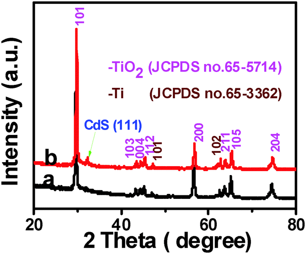
Crystal structure of the samples was determined by X-ray diffraction (XRD). It can be seen from Fig. 1 that TiO2 NBs and the TiO2 NB–CdS QD heterostructure demonstrate similar XRD patterns, for both of which the dominant peaks at 2θ values of 29.4°, 43.2°, 44.2°, 45.1°, 56.4°, 63.5°, 64.9° and 74.3° are undisputedly indexed to (101), (103), (004), (112), (200), (105), (211) and (204) crystallographic planes of anatase TiO2 (JCPDS no. 65-5714), and the peaks at 2θ values of 47.0° and 62.4° are attributed to (101) and (102) crystal planes of Ti (JCPDS no. 65-3362) from the Ti foil. The characteristic peak at the 2θ value of 32.4° in Fig. 1b can be unambiguously indexed to the (111) crystallographic plane of the cubic blende structure of CdS (JCPDS no. 89-0440), indicating the deposition of CdS QDs on the TiO2 NB framework. Notably, no other typical CdS peaks are observed in the XRD pattern of the TiO2 NB–CdS QD heterostructure, which might be due to the low amount and relatively low diffraction intensity of CdS QD peaks in comparison with that of predominant bulk TiO2 NB peaks.
 |
| | Fig. 1 XRD patterns of (a) TiO2 NBs and (b) TiO2 NB–CdS QD heterostructure. | |
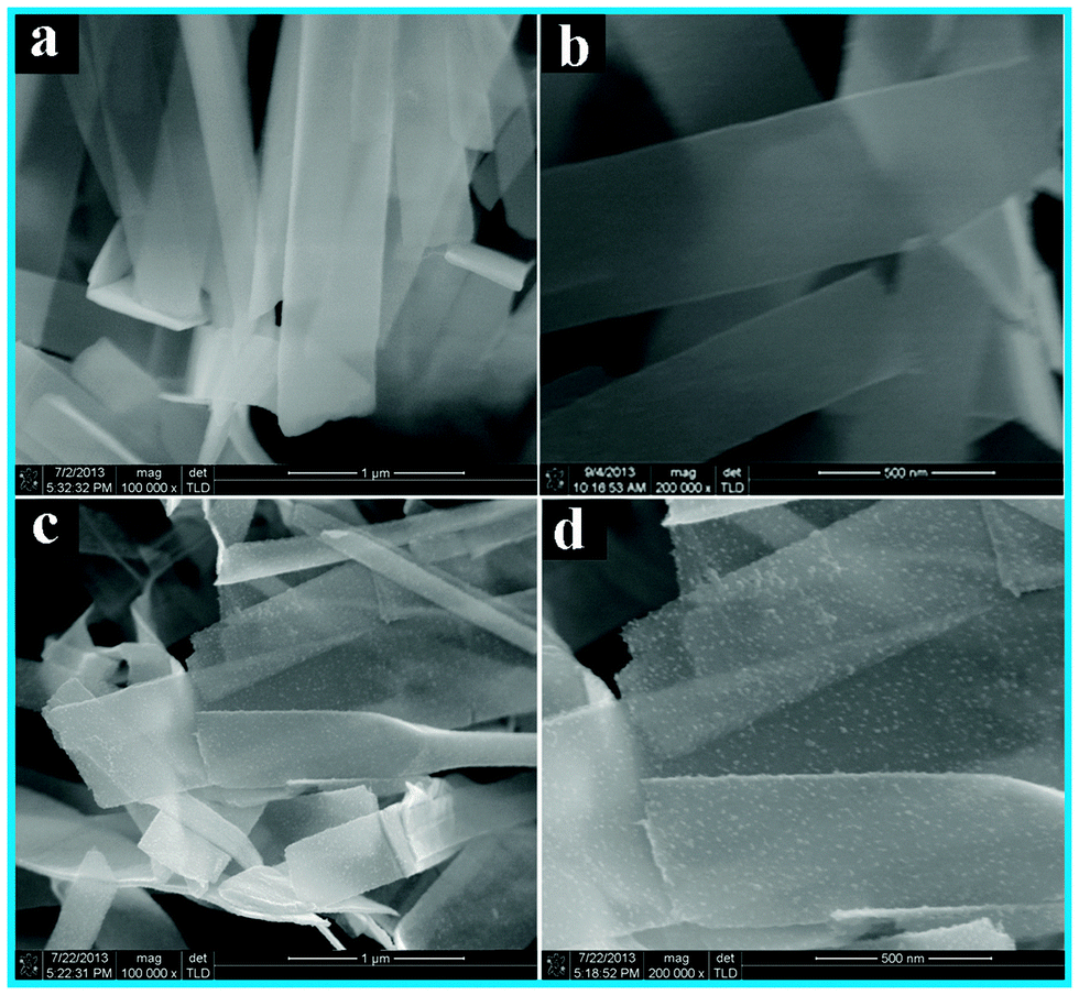
Scanning electron microscopy (SEM) images were utilized to directly analyze the microscopic morphology of the samples. As shown in Fig. 2a and b, blank TiO2 NBs exhibit a typical nanobelt morphology with a smooth surface along with a width of ca. 450 nm. In contrast, Fig. 2c and d clearly show that surface roughness of the TiO2 NB–CdS QD heterostructure remarkably increases as compared with blank TiO2 NBs, in which a large amount of CdS QDs was uniformly deposited on the surface. The results suggest that negatively charged CdS QDs stemming from deprotonated carboxyl groups (–COO−) on the surface (Fig. S1c, ESI†) can spontaneously and efficiently self-assemble to the amine-functionalized positively charged TiO2 NB substrate under pronounced electrostatic interaction, therefore resulting in monodisperse deposition of CdS QDs on the TiO2 NB surface. On the other hand, it is worthwhile that the carboxyl groups on the CdS QD surface may also react with the amino groups of APTES to form the amide bonds during the assembly process, which may additionally contribute to the uniform distribution of CdS QDs on the TiO2 NB substrate. Consequently, the material assembly mechanism is predominantly driven by the pronounced electrostatic attractive interaction and chemical covalent bonding between the positively charged TiO2 NB substrate and negatively charged CdS QD ingredients.
 |
| | Fig. 2 Typical FESEM images of (a & b) TiO2 NBs and (c & d) TiO2 NB–CdS QD heterostructure. | |
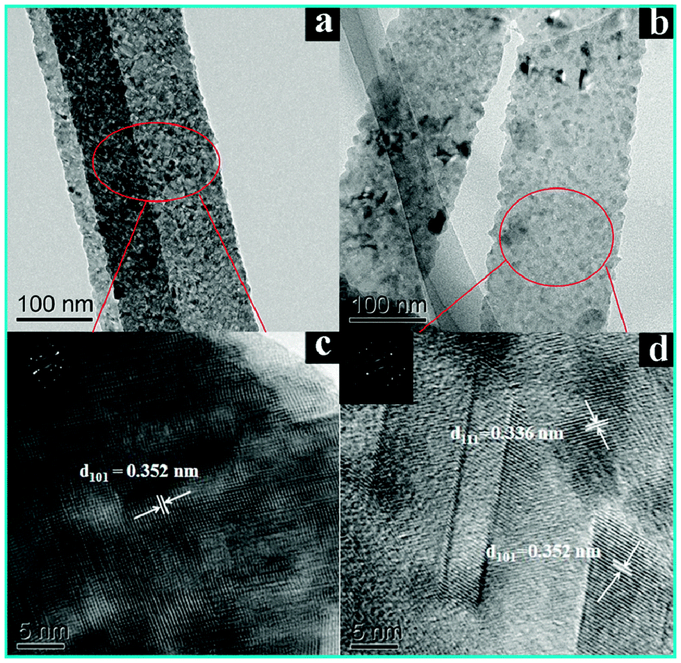
Fig. 3 displays the transmission electron microscopy (TEM) images of the samples. As displayed in Fig. 3a, the TiO2 NB substrate shows a typical 1D flat nanostructure. The high-resolution TEM image in Fig. 3c reveals a well-resolved lattice fringe of about 3.52 Å, which corresponds to the (101) crystal plane of TiO2, suggesting the good crystallinity of TiO2 after heat treatment (450 °C, 1 h, in air). Fig. 3b shows the TEM image of the TiO2 NB–CdS QD heterostructure in which CdS QDs with a mean diameter of ca. 5.6 nm (Fig. S1d, ESI†) were evenly deposited on the TiO2 NB surface leading to a much rougher surface than blank TiO2 NBs. In addition, as shown in Fig. 3d, the HRTEM image of the TiO2 NB–CdS QD heterostructure reveals a distinct lattice fringe of ca. 3.36 Å which corresponds to the (111) crystal plane of the CdS phase, thus additionally confirming the successful deposition of CdS QDs on the nanobelt surface which is in line with the XRD results.
 |
| | Fig. 3 Typical TEM images of (a) TiO2 NBs and (b) TiO2 NB–CdS QD heterostructure. HRTEM images of (c) TiO2 NBs and (d) TiO2 NB–CdS QD heterostructure. | |
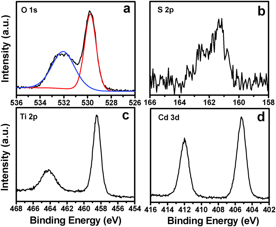
X-ray photoelectron spectroscopy (XPS) measurements were performed to explore the composition and elemental chemical state of the TiO2 NB–CdS QD heterostructure. The survey spectrum (Fig. S2a, ESI†) of the hybrid heterostructure reveals the presence of C 1s, O 1s, N 1s, Ti 2p, S 2p and Cd 3d signals. Specifically, as shown in Fig. S2c (ESI†), three peaks with binding energies (BEs) of 284.59, 286.08 and 287.73 eV in the high-resolution C 1s spectrum are attributed to C–C/C–H species from aliphatic hydrocarbon chains of APTES, C–OH/C–O–C species from the absorbed water molecule, and –COO− functional groups from the TGA ligand, respectively.29,33 Moreover, Fig. 4a displays the deconvoluted O 1s peaks with characteristic BEs of 529.76 and 532.05 eV, which can be attributed to the lattice oxygen atoms of TiO2 and –COO− groups from TGA, respectively.22 Furthermore, Fig. 4b shows the high-resolution spectrum of S 2p, in which the pronounced peak located at 161.3 eV for S 2p3/2 can be assigned to two chemical species with analogue BEs, that is, S2− from the bulk CdS phase and S–CdS from chemical bonding of TGA on the CdS surface.34 Therefore, based on the above analysis, it can be deduced that the electrostatic attraction based self-assembly buildup is beneficial for the spontaneous and uniform deposition of tailor-made CdS QDs on the TiO2 NB matrix. In addition, as shown in Fig. 4c, BE of Ti 2p3/2 at 458.48 eV agrees well with the Ti4+ oxidation state in TiO2,26 and the high-resolution spectrum of Cd 3d (Fig. 4d) located at 405.25 eV for Cd 3d5/2 corresponds to chemical species of Cd2+,34 which indicates that the chemical properties of CdS QDs and the TiO2 NB substrate were not changed during the self-assembly process. Alternatively, the high-resolution spectrum of N 1s (Fig. S2c, ESI†) and FTIR results (Fig. S3, ESI†) evidence the attachment of APTES on the surface of the TiO2 NB substrate. The detailed chemical bond species versus BE and the elemental concentration of the TiO2 NB–CdS QD heterostructure are tabulated in Tables S1 and S2 (ESI†), respectively.
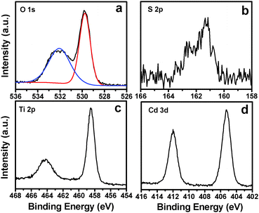 |
| | Fig. 4 High-resolution XPS spectra of (a) O 1s, (b) S 2p, (c) Ti 2p and (d) Cd 3d for the TiO2 NB–CdS QD heterostructure. | |
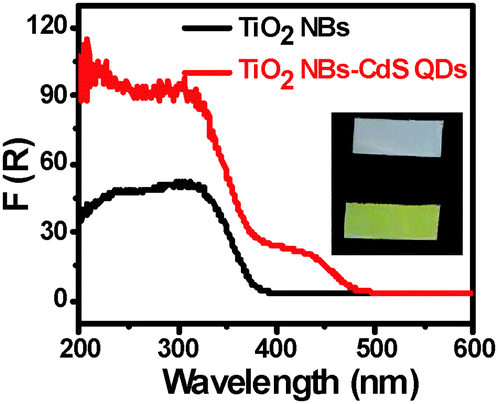
Optical absorption properties of the sample are closely related to its photocatalytic performance, and it is generally assumed that the material with a better optical absorption may result in enhanced photoactivity. UV-vis diffuse reflectance spectra (DRS) have been harnessed to determine the optical properties of the samples. It can be seen from Fig. 5, as compared with blank TiO2 NBs, that CdS QD deposition exerts a significant influence on the optical properties of the TiO2 NB–CdS QD heterostructure with its absorption band extending from the UV to visible region (i.e. ca. from 400 to 500 nm), which is consistent with the color change of the samples (inset of Fig. 5 and Fig. S4, ESI†). The substantially enhanced light absorption may be beneficial for improving the visible-light-responsive photocatalytic performances of TiO2 NB–CdS QD nanocomposites.
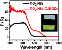 |
| | Fig. 5 UV-vis diffuse reflectance spectra (DRS) of TiO2 NBs and the TiO2 NB–CdS QD heterostructure with corresponding digital photographs in the inset (white for TiO2 NBs and yellow for TiO2 NB–CdS QDs). | |
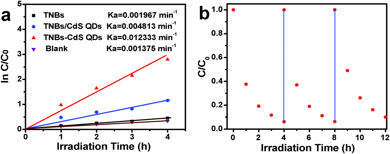
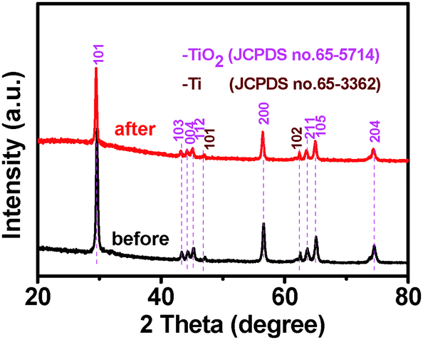
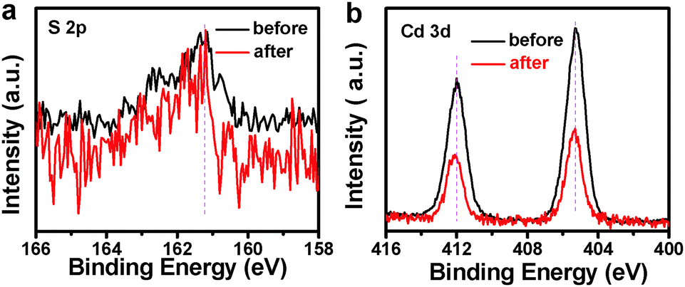
Photocatalytic performances of the samples were evaluated by the liquid-phase degradation of aqueous RhB solution under visible light irradiation (λ > 420 nm). Blank experiments (without light or catalyst) show negligible photoactivities (Fig. S5, ESI†), indicating that the degradation was truly driven by a photocatalytic process. As shown in Fig. 6a, the photodegradation efficiency of the samples follows the order of TiO2 NB–CdS QDs > TiO2 NBs/CdS QDs > TiO2 NBs, among which the TiO2 NB–CdS QD heterostructure exhibits the optimum photocatalytic performances. Specifically, the blank TiO2 NB substrate exhibits negligible photoactivity; however, the self-assembled TiO2 NB–CdS QD heterostructure exhibits significantly enhanced photocatalytic performances in comparison with the TiO2 NB/CdS QD counterpart fabricated by the direct deposition of CdS QDs onto the TiO2 NBs substrate without surface modification (middle, Fig. S4, ESI†). Moreover, as revealed in Fig. 6b, cycling measurements imply that the TiO2 NB–CdS QD heterostructure is relatively stable when it was subjected to successive photocatalytic reactions as compared with the pure CdS QD film (Fig. S6, ESI†), this may be ascribed to the protection effect of the surface ligand (TGA) on the CdS QD surface which may be preferentially oxidized by photogenerated holes instead of the blank CdS phase, thus reducing the probability of photocorrosion over CdS QDs. Consistently, it was found that XRD patterns of the TiO2 NB–CdS QD heterostructure before and after cycling photocatalytic reactions were retained as shown in Fig. 7, which verifies structural intactness of the hybrid nanostructure during the photocatalytic reaction. Furthermore, as shown in Fig. 8, it can be clearly seen that high-resolution XPS peaks of Cd 3d and S 2p for the TiO2 NB–CdS QD heterostructure before and after cycling photodegradation reactions exhibit no BE shift, which suggests that chemical states of Cd 3d and S 2p elements of the TiO2 NB–CdS QD heterostructure were unchanged. Therefore, both XRD and XPS results suggest the favorable photostability of the TiO2 NB–CdS QD heterostructure under visible light irradiation, which is of great importance to the practical applications since no separation of the photocatalyst is needed owing to the direct growth properties of TiO2 NBs on the Ti foil, thus demonstrating inimitable advantage over conventional particulate photocatalysts.
 |
| | Fig. 6 (a) Photocatalytic performances of TiO2 NBs and the TiO2 NB–CdS QD heterostructure toward the degradation of RhB under visible light irradiation (λ > 420 nm) and (b) cycling photoreaction of the TiO2 NB–CdS QD heterostructure. | |
 |
| | Fig. 7 XRD patterns of the TiO2 NB–CdS QD heterostructure before and after cycling photodegradation reactions. | |
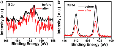 |
| | Fig. 8 High-resolution XPS spectra of (a) S 2p and (b) Cd 3d for the TiO2 NB–CdS QD heterostructure before and after cycling photodegradation reactions. | |
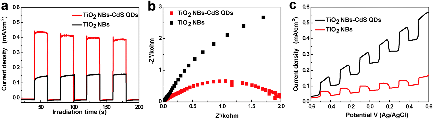
To disclose the origin accounting for the significantly enhanced photocatalytic performance of the TiO2 NB–CdS QD heterostructure, photoelectrochemical investigations have therefore been performed. It has been well-established that photocurrent originates by the diffusion of the photogenerated electrons to the back contact and, meanwhile, the photoinduced holes were taken up by the hole acceptor in the electrolyte.35 As displayed in Fig. 9a, the photocurrent response of the TiO2 NB–CdS QD heterostructure is remarkably higher than that of blank TiO2 NBs and the pure CdS QD film (Fig. S7a, ESI†), suggesting more efficient separation and a longer lifetime of photoexcited electron–hole pairs over the TiO2 NB–CdS QD heterostructure. In addition, the separation efficiency of photogenerated electrons and holes was further probed by Electrochemical impedance spectroscopy (EIS), which has been established as an effective tool to study the interface properties of surface-modified electrodes.33 As shown in Fig. 9b, the TiO2 NB–CdS QD heterostructure exhibits a dramatic decrease of the high-frequency arc as compared to blank TiO2 NBs and pure CdS QD film electrodes (Fig. S7b, ESI†), which indicates that the TiO2 NB–CdS QD heterostructure possesses a better separation efficiency of photogenerated charge carriers and a faster charge transfer rate across the interface. In addition, Fig. 9c shows the photocurrent density versus the applied bias voltage plot under visible light irradiation, in which the photocurrent density of the TiO2 NB–CdS QD heterostructure increases with the forward applied bias voltage, indicative of a typical n-type semiconductor.29 Under illumination, the TiO2 NB–CdS QD heterostructure always shows a higher photocurrent density than blank TiO2 NBs in the whole potential profile, thus once again suggesting efficient charge separation over the self-assembled hybrid nanostructure. On the other hand, in addition to the improved charge separation efficiency, it should be noted that the enhanced absorption of the TiO2 NB–CdS QD heterostructure for light harvesting owing to the CdS QD sensitization, as evidenced by the DRS result, may also contribute to the significantly enhanced photocatalytic performance.
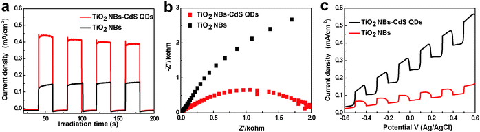 |
| | Fig. 9 (a) Transient photocurrent responses under 0.5 V bias versus Ag/AgCl electrode, (b) electrochemical impedance spectroscopy (EIS) Nyquist impedance plots, and (c) photocurrent density versus potential curves of blank TiO2 NBs and the TiO2 NB–CdS QD heterostructure in 1 M KOH (pH = 13.9) aqueous solution under visible light irradiation (λ > 420 nm), the amplitude of the sinusoidal wave was set at 10 mV and the frequency varied from 100 kHz to 0.05 Hz. | |
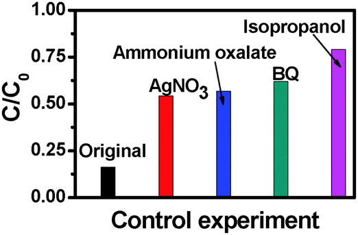
To further understand the role of photogenerated radical species in the photocatalytic process over the TiO2 NB–CdS QD heterostructure under visible light irradiation a series of controlled experiments with the addition of different radical scavengers for quenching hydroxyl radicals, superoxide radicals, holes, and electrons, respectively, have been performed. As shown in Fig. 10, the photodegradation efficiency of the TiO2 NB–CdS QD heterostructure is concurrently inhibited in the presence of all these four scavengers. Specifically, when the isopropanol scavenger for hydroxyl radicals is added into the reaction system, photoactivity is remarkably prohibited, and analogous results were also observed when the benzoquinone (BQ) scavenger for superoxide radicals, the ammonium oxalate scavenger for holes, and the AgNO3 scavenger for electrons were added into the reaction system. The prohibited intensity of scavengers follows the order of: isopropanol > BQ > ammonium oxalate > AgNO3. Thus, it can be concluded that hydroxyl radicals, holes, electrons and superoxide radicals all exert profound and a synergistic influence on the photocatalytic performance of the TiO2 NB–CdS QD heterostructure, among which, hydroxyl and superoxide radicals play much more important roles than electrons and holes. It should be emphasized that although photogenerated electrons are not able to directly participate in the degradation of dye pollutants, they can activate oxygen dissolved in the aqueous solution to produce a large amount of hydroxyl radicals and superoxide radicals which fulfill the direct oxidation of dyes. The transformation of electrons to hydroxyl radicals and superoxide radicals can be expressed by the following formula.
Based on the above analysis, the photocatalytic mechanism of the TiO2 NB–CdS QD heterostructure was tentatively delineated in Scheme 2. Under visible light irradiation (λ > 420 nm), electrons are excited from the valence band (VB) of CdS to the conduction band (CB) leaving holes in the VB, thereby forming the electron–hole pairs. The photogenerated electrons from the CB of CdS can be easily transferred to the CB of TiO2 NBs due to the well-crystallized and self-aligned properties of the TiO2 NB scaffold grown on the conducting Ti substrate and, more importantly, the favorable energy level (i.e. typical type II band alignment) between CdS QDs and TiO2 NBs, thus the lifetime of photogenerated charge carriers is significantly prolonged. In this way, various oxidative active species including hydroxyl radicals and superoxide radicals resulting from the reactions between electron and oxygen or water molecules absorbed on the TiO2 NB framework concurrently oxidize organic dye pollutants to CO2 and H2O, thus contributing to the significantly enhanced photocatalytic performances of the TiO2 NB–CdS QD heterostructure. On the other hand, it should be particularly pointed out that the photogenerated holes are able to directly oxidize the organic dye pollutant to fulfill the mineralization process.
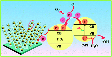 |
| | Scheme 2 Schematic illustration showing the photocatalytic mechanism of the TiO2 NB–CdS QD heterostructure. | |
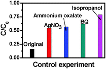 |
| | Fig. 10 Control experiments using different radical scavengers for the photocatalytic degradation of RhB aqueous solution over the TiO2 NB–CdS QD heterostructure, (a) reaction in the absence of any radical scavengers (viz. original), (b) reaction with AgNO3 as a scavenger for photogenerated electrons, (c) reaction with ammonium oxalate as a scavenger for photogenerated holes, (d) reaction with benzoquinone (BQ) as a scavenger for superoxide radicals, and (e) reaction with isopropanol as a scavenger for hydroxyl radicals under visible light irradiation for 4 h (λ > 420 nm). | |
4. Conclusions
In summary, a well-defined TiO2 NB–CdS QD heterostructure has been fabricated by a facile and efficient self-assembly strategy, by which tailor-made negatively charged CdS QDs were spontaneously and uniformly anchored to the APTES-modified positively charged TiO2 NB framework based on pronounced electrostatic interaction. It was found that the as-prepared TiO2 NB–CdS QD heterostructure exhibits significantly enhanced photocatalytic performance in comparison with blank TiO2 NBs and unmodified binary counterparts. The significantly enhanced photoactivity of the TiO2 NB–CdS QD heterostructure can be ascribed to the intimate interfacial integration between TiO2 NBs and CdS QDs afforded by the self-assembly buildup, which results in a prolonged lifetime of photogenerated electron–hole pairs over the hybrid nanostructure. Photoelectrochemical measurements have unambiguously ascertained the efficient separation of photogenerated electron–hole charge carriers during the photocatalytic process. Moreover, the possible photocatalytic mechanism was proposed and the predominant photogenerated active species including hydroxyl radicals and superoxide radicals have been determined to play the most dominant roles in the significantly enhanced photocatalytic performance of the TiO2 NB–CdS QD heterostructure under visible light irradiation. It is hoped that our work could open up a new paradigm for designing narrow bandgap semiconductor/1D semiconductor heterostructures for extensive photocatalytic applications.
Acknowledgements
This work was supported by the Nanyang Technological University startup grant: M4080977.120 and Singapore Ministry of Education Academic Research Fund (AcRF) Tier 1: M4011021.120 and Singapore-Berkeley Research Initiative for Sustainable Energy (SinBeRise).
References
- A. I. Hochbaum, R. Chen, R. D. D. W. Liang, E. C. Garnett, M. Najarian, A. Majumdar and P. Yang, Nature, 2008, 451, 163–167 CrossRef CAS PubMed.
- W. U. Huynh, J. J. Dittmer and A. P. Alivisatos, Science, 2002, 295, 2425–2427 CrossRef CAS PubMed.
- A. Kargar, K. Sun, Y. Jing, C. Choi, H. Jeong, Y. Zhou, K. Madsen, P. Naughton, S. Jin, G. Y. Jung and D. Wang, Nano Lett., 2013, 13, 3017–3022 CrossRef CAS PubMed.
- C. Liu, J. Tang, H. M. Chen, B. Liu and P. Yang, Nano Lett., 2013, 13, 2989–2992 CrossRef CAS PubMed.
- B. Tian, X. Zheng, T. J. Kempa, Y. Fang, N. Yu, G. Yu, J. Huang and C. M. Lieber, Nature, 2007, 449, 885–889 CrossRef CAS PubMed.
- B. Y. Xia, H. B. Wu, Y. Yan, X. W. Lou and X. Wang, J. Am. Chem. Soc., 2013, 135, 9480–9485 CrossRef CAS PubMed.
- Y. J. Hwang, C. Hahn, B. Liu and P. Yang, ACS Nano, 2012, 6, 5060–5069 CrossRef CAS PubMed.
- J. Lin, J. Shen, R. Wang, J. Cui, W. Zhou, P. Hu, D. Liu, H. Liu, J. Wang, R. I. Boughton and Y. Yue, J. Mater. Chem., 2011, 21, 5106–5113 RSC.
- W. Li, Y. Bai, W. Liu, C. Liu, Z. Yang, X. Feng, X. Lu and K. Y. Chan, J. Mater. Chem., 2011, 21, 6718–6724 RSC.
- P. Hu, G. Du, W. Zhou, J. Cui, J. Lin, H. Liu, D. Liu, J. Wang and S. Chen, ACS Appl. Mater. Interfaces, 2010, 11, 3263–3269 Search PubMed.
- J. Thomas and M. Yoon, Appl. Catal., B, 2012, 111, 502–508 CrossRef PubMed.
- D. Wang, W. Zhou, P. Hu, Y. Guan, L. Chen, J. Li, G. Wang, H. Liu, J. Wang, G. Cao and H. Jiang, J. Colloid Interface Sci., 2012, 388, 144–150 CrossRef CAS PubMed.
- X. Pan, Y. Zhao, S. Liu, C. L. Korzeniewski, S. Wang and Z. Fan, ACS Appl. Mater. Interfaces, 2012, 4, 3944–3950 CAS.
- Z. Xiong and X. S. Zhao, J. Mater. Chem. A, 2013, 1, 7738–7744 CAS.
- H. Li, M. Eastman, R. Schaller, W. Hudson and J. Jiao, J. Nanosci. Nanotechnol., 2011, 11, 8517–8521 CrossRef CAS PubMed.
- Y. Luo, J. Luo, W. Zhou, X. Qi, H. Zhang, D. Y. W. Yu, C. M. Li, H. J. Fan and T. Yu, J. Mater. Chem. A, 2013, 1, 273–281 CAS.
- H. G. Yang and H. C. Zeng, J. Am. Chem. Soc., 2005, 127, 270–278 CrossRef CAS PubMed.
- W. Zhou, H. Liu, J. Wang, D. Liu, G. Du and J. Cui, ACS Appl. Mater. Interfaces, 2010, 2, 2385–2392 CAS.
- W. Zhou, Z. Yin, Y. Du, X. Huang, Z. Zeng, Z. Fan, H. Liu, J. Wang and H. Zhang, Small, 2013, 9, 140–147 CrossRef CAS PubMed.
- D. F. Watson, J. Phys. Chem. Lett., 2010, 1, 2299–2309 CrossRef CAS.
- D. R. Baker and P. V. Kamat, Adv. Funct. Mater., 2009, 19, 805–811 CrossRef CAS.
- F.-X. Xiao, J. Miao, H. Y. Wang and B. Liu, J. Mater. Chem. A, 2013, 1, 12229–12238 CAS.
- H. Wang, Y. Bai, H. Zhang, Z. Zhang, J. Li and L. Guo, J. Phys. Chem. C, 2010, 114, 16451–16455 CAS.
- K. Wang, S. Wan, Q. Liu, N. Yang and J. Zhai, RSC Adv., 2013, 3, 23755–23761 RSC.
- G. Li, L. Wu, F. Li, P. Xu, D. Zhang and H. Li, Nanoscale, 2013, 5, 2118–2125 RSC.
- P. Sudhagar, J. H. Jung, S. Park, R. Sathyamoorthy, H. Ahn and Y. S. Kang, Electrochim. Acta, 2009, 55, 113–117 CrossRef CAS PubMed.
- H. Wang, G. Wang, Y. Ling, M. Lepert, C. Wang, J. Z. Zhang and Y. Li, Nanoscale, 2012, 4, 1463–1466 RSC.
- W. T. Sun, Y. Yu, H. Y. Pan, X. F. Gao, Q. Chen and L. M. Peng, J. Am. Chem. Soc., 2008, 130, 1124–1125 CrossRef CAS PubMed.
- F.-X. Xiao, J. Miao and B. Liu, Mater. Horiz., 2014, 1, 259–263 RSC.
- X. Yu, R. Liu and G. Zhang, RSC Adv., 2013, 3, 8351–8355 RSC.
- F. Zhu, H. Dong, Y. Wang, D. Wu, J. Li, J. Pan, Q. Li, X. Ai, J. Zhang and D. Xu, Phys. Chem. Chem. Phys., 2013, 15, 17798–177803 RSC.
- N. Wu, J. Wang, D. N. Tafen, H. Wang, J. G. Zheng, J. P. Lewis, X. Liu, S. S. Leonard and A. Manivannan, J. Am. Chem. Soc., 2010, 132, 6679–6685 CrossRef CAS PubMed.
- F.-X. Xiao, J. Phys. Chem. C, 2012, 116, 16487–16498 CAS.
- T. Nakanishi, B. Ohtani, K. Shimazu and K. Uosaki, Chem. Phys. Lett., 1997, 278, 233–237 CrossRef CAS.
- N. Zhang, Y. Zhang, X. Pan, X. Fu, S. Liu and Y. J. Xu, J. Phys. Chem. C, 2011, 115, 136–9145 Search PubMed.
Footnote |
| † Electronic supplementary information (ESI) available. See DOI: 10.1039/c4nj01346h |
|
| This journal is © The Royal Society of Chemistry and the Centre National de la Recherche Scientifique 2015 |
Click here to see how this site uses Cookies. View our privacy policy here.