Versatile third components for efficient and stable organic solar cells
Pei
Cheng
ac and
Xiaowei
Zhan
*b
aBeijing National Laboratory for Molecular Sciences and CAS Key Laboratory of Organic Solids, Institute of Chemistry, Chinese Academy of Sciences, Beijing 100190, China
bDepartment of Materials Science and Engineering, College of Engineering, Key Laboratory of Polymer Chemistry and Physics of Ministry of Education, Peking University, Beijing 100871, China. E-mail: xwzhan@pku.edu.cn
cUniversity of Chinese Academy of Sciences, Beijing 100049, China
First published on 23rd June 2015
Abstract
Organic solar cells (OSCs) with a third component, consisting of a donor material, an acceptor material and a third component (organic or inorganic, semiconductor or insulator), received increasing attention in the last five years and the power conversion efficiencies approached 10%. Compared with the traditional binary (two-component) blend, three-component OSCs presented some advantages: broader and stronger absorption, more efficient charge transfer, more efficient charge transport pathways, better charge extraction at the electrodes and improved stability. Various types of third components, such as light-absorbing small molecules or polymers, fullerene or non-fullerene acceptors, metal- or carbon-based nanomaterials, quantum dots, and polymer or small molecule nonvolatile additives were used in OSCs. In this contribution, we review the recent developments in three-component OSCs using various third components. In particular, the absorption complementation, phase separation and the nanostructure in three-component OSCs are addressed.
1. Introduction
Organic solar cells (OSCs) are a promising cost-effective alternative for the utilization of solar energy, and present advantages, such as their simple preparation, low cost, light weight and large-area fabrication on flexible substrates. Much attention has been focused on the development of OSCs, which have seen a dramatic rise in efficiency over the last decade.1–15At the early stage of OSC development (1950s–1980s), the active layer typically consisted of a single component organic material, and yielded a very low power conversion efficiency (PCE).16 Since the bulk heterojunction (BHJ) concept was reported in 1995,17 a two-component (binary) blend had been predominant as the active layer. Relative to the single-component OSCs, the binary blend OSCs presented some advantages: efficient charge separation resulting from photoinduced electron transfer at the donor/acceptor (D/A) interfaces, and a high charge collection efficiency resulting from a bi-continuous network of the D/A blend. As a result, the binary blend OSCs exhibited PCEs of up to 10% for a single junction18 and 11%19 for a tandem junction.
Although the PCEs of binary blend OSCs were improved relative to 20 years ago, there are still some deficiencies in binary blend OSCs. For example, a poly(3-hexylthiophene) (P3HT)/[6,6]-phenyl-C61-butyric-acid-methyl-ester (PC61BM) binary blend was most widely used in OSCs using spin coating20–22 or a roll-to-roll (R2R) printing process.23–26 This binary blend OSC still has some serious problems: (1) the absorption spectrum of this blend film is not broad (<650 nm) and not intense (a very thick film is required);22 (2) the offsets of the highest occupied molecular orbital (HOMO) and lowest unoccupied molecular orbital (LUMO) energy levels are considerably larger than 0.3 eV (the minimum requirement for charge transfer7), leading to energy loss and a reduced charge transfer efficiency;27 (3) a simple blend of a donor and an acceptor cannot build efficient charge transport pathways; (4) the Schottky contact between the active layer and the electrodes10 and an unfavorable vertical phase separation28–30 hinder efficient charge extraction at the electrodes; and (5) the morphology of the blend film is not stable during heat exposure or long term use.31,32 In recent years, low-bandgap (LBG) polymers were developed to replace P3HT.33–44 A LBG polymer/PCBM binary blend can solve some of the problems above, but a simple blend of them is still not good enough to achieve very high PCEs and good stability.
Three-component OSCs consisting of a donor material, an acceptor material and a third component received increasing attention in the last five years.45–48 Compared with the binary blend, OSCs with a third component present some advantages: broader and stronger absorption, more efficient charge transfer, more efficient charge transport pathways, better charge extraction at the electrodes and improved stability. In the most recent two years, three-component OSCs have rapidly developed, and their PCEs have exceeded 8% for both an inorganic third component49–54 and an organic third component.55–65 It is worth mentioning that most of the reported OSCs with a third component were fabricated without an inverted structure, interlayer, tandem structure or optimized optical structure. The PCEs of three-component OSCs could be improved to >10% with further device work. OSCs with a third component are emerging as a new horizon in this field.
In this review, we focus our discussion on the recent developments in OSCs with a third component, especially on those accomplished in the last two years. Firstly, we introduce the fundamental design rules of OSCs with a third component. Then, we survey and analyze what is currently known concerning OSCs with a third component in terms of four types of structure: donor/organic light-absorbing molecule/acceptor, donor/acceptor/acceptor, donor/inorganic nanomaterials/acceptor and donor/organic nonvolatile additives/acceptor. The reasons for the better performance of OSCs with a third component relative to their control binary blend devices are also discussed. Finally, we address the possible research direction in the near future.
2. Fundamental design rules of three-component OSCs
In order to achieve highly efficient and stable OSCs, the third component is involved in every important physical process in OSCs. In this part, we discuss the fundamental design rules for OSCs with a third component in terms of light absorption, charge transfer, charge transport, charge extraction and morphology stability.2.1. Broader and stronger absorption
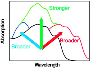
Light absorption is the first step of the photovoltaic process. In most systems of OSCs, the vast majority of the photocurrent is attributed to the absorption of the donor materials. Lowering the bandgap (Eg) of the donor materials can extend the absorption spectrum, but will decrease the open circuit voltage (VOC) simultaneously.43,66 The absorption spectra of the most widely used donor materials, such as P3HT (Eg = 1.9 eV, absorption edge < 650 nm) and poly[[4,8-bis[(2-ethylhexyl)oxy]benzo[1,2-b:4,5-b′]dithiophene-2,6-diyl][3-fluoro-2-[(2-ethylhexyl)-carbonyl]-thieno-[3,4-b]thiophenediyl]] (PTB7)35 (Eg = 1.65 eV, absorption edge < 750 nm), do not match well with the solar spectrum.67 Relative to broadening the absorption in the long wavelength region, broadening the absorption in the short wavelength region has received less attention, although it is also important for some systems. The molar absorption coefficient of organic materials is higher than that of inorganic materials, but is not high enough to absorb all light in their absorption spectrum when the films are thin (e.g. 100 nm). The thicker films can absorb more light, but the low mobility of organic materials does not allow the films to be very thick. To design a three-component OSC, the third component can play one or more roles (Fig. 1): it can show a strong light absorption which is complementary to the absorption of the host donor and acceptor materials; it can enhance the absorption of the active layer in its original absorption region by some optical effects; and it can enhance the crystallinity or the aggregation of the polymer donor to red-shift or improve its absorption.2.2. More efficient charge transfer at the D/A interfaces
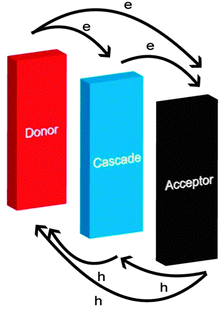
The offsets of the HOMOs and LUMOs of the donor and the acceptor should be suitable. Too small offsets cannot provide a driving force large enough for charge transfer,68,69 while too large offsets cannot suppress geminate charge recombination.27 In a cascade energy heterojunction, the HOMO and LUMO levels of the cascade are located between the HOMOs and LUMOs of the donor and acceptor materials (Fig. 2). This is an efficient way to increase the charge transfer routes (donor–cascade, cascade–acceptor, donor–acceptor)57 and suppress geminate charge recombination.27 Typical cascade energy heterojunctions are ternary blends and tri-layers.70 A ternary blend of a donor, an acceptor and a cascade is a simple and widely used way to fabricate a cascade energy heterojunction. On the other hand, the larger area of D/A interfaces can not only induce more efficient exciton dissociation and photoinduced charge transfer, but also cause more charge recombination. Thus, to design an OSC with a third component, the third component should have suitable energy levels to fabricate a cascade energy heterojunction and the D/A interface should be adjusted to a suitable area.2.3. More efficient charge transport pathways
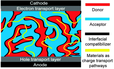
Charge transport is very important for OSCs; efficient charge transport can endure a thicker film of the active layer which can absorb more light and is suitable for R2R fabrication.71–73 The charge transport depends on the materials themselves, the molecular packing, the domain purity, the D/A interfaces, additional transport pathways and the network of the donor and the acceptor. OSCs with a third component can be designed to build more efficient charge transport pathways (Fig. 3). The third component can play one or more roles: it can induce more ordered molecular packing (maybe crystallization) of the donor or the acceptor; it can purify the domains of the donor or the acceptor; it can function as an interfacial compatibilizer; and it can act as additional hole or electron transport pathways.2.4. More efficient charge extraction at the electrodes
Charge extraction is the last step of the photovoltaic process, which is very important, but the efficiency is limited in simple binary blend systems.74–76 For efficient charge extraction, the vertical phase separation of the active layer and the contact between the electrodes and the active layer play very important roles. In spin-coated polymer/fullerene blends, donor polymers are apt to aggregate on the top surface due to the relatively low surface energy compared with fullerene acceptors (Fig. 4a).28,77 As a result, the holes transported by the polymer donor and the electrons transported by fullerene are extracted by the wrong electrode, the cathode and anode, respectively. Thus, the vertical phase separation in this simple binary blend structure is not desired for charge extraction.78,79 The Schottky contact between the active layer and the electrodes is harmful for charge extraction,10 but the ideal ohmic contact between the active layer and the electrodes is hard to achieve without inserting some kinds of buffer layers.80,81 OSCs with a third component can be designed to achieve more efficient charge extraction at the electrodes: (1) the third component can induce efficient vertical phase separation (like a p–i–n type29); (2) the third component can self-organize as a hole or electron buffer layer to form a better contact between the active layer and the electrodes (Fig. 4b).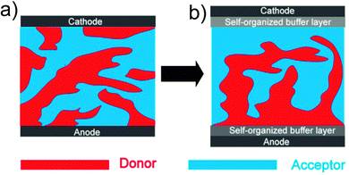 | ||
| Fig. 4 Schematic diagrams of active layers: (a) a simple binary blend; (b) a ternary blend with efficient charge extraction at the electrodes. | ||
2.5. Better morphology stability
For industrial mass production of OSCs, the stability is as important as the efficiency.31,82,83 However, in the most widely used binary blend systems, the electron acceptor PCBM tends to aggregate into big clusters after some time or after thermal treatment, which destroys the morphology of the active layer and reduces the PCE drastically.84–86 OSCs with a third component can be designed to achieve better stability compared to the control devices; the third component can suppress the aggregation of PCBM or solidify the morphology of the active layer as a cross-linker or freeze the scale of phase separation via some special intermolecular interactions.3. Main types of three-component OSCs
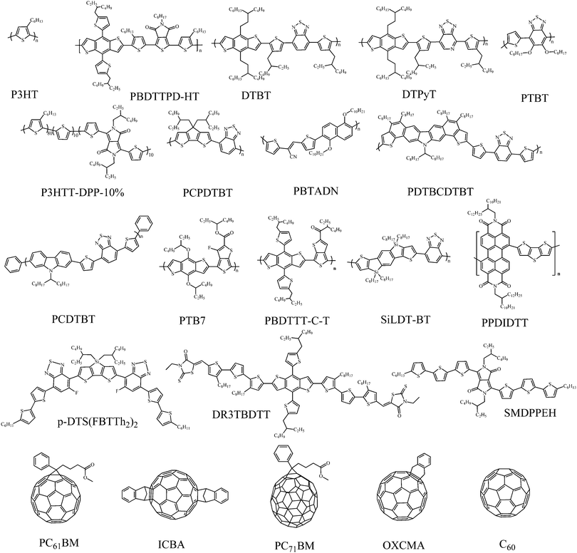
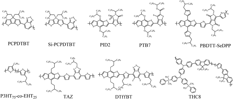
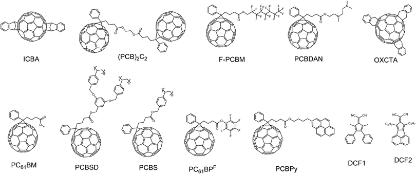
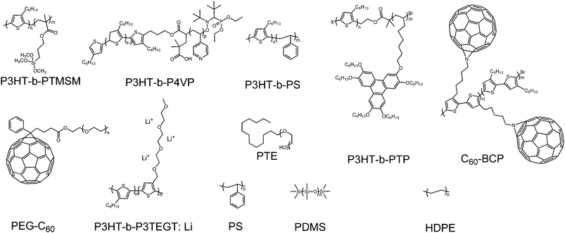
In this part, we focus our discussion on the recent development of OSCs with a third component, especially on the development accomplished in the last two years. The main four types of OSCs with a third component include donor/organic light-absorbing molecule/acceptor (third component: a light-absorbing polymer and a small molecule), donor/acceptor/acceptor (third component: an acceptor polymer and a small molecule), donor/inorganic nanomaterial/acceptor (third component: a metal nanomaterial, quantum dot and a carbon-based nanomaterial), and donor/organic nonvolatile additive/acceptor (third component: a polymer additive and a nonvolatile small molecule additive). The photovoltaic properties of devices without and with the addition of the third component are listed in Tables 1–6; the ratio of the third component is the weight ratio of the third component to the total weight of the donor, acceptor and third component in OSCs. The molecular structures of the donor and acceptor materials used in this review are shown in Chart 1. The molecular structures of the different third components are shown in Charts 2–6.| Donor | Acceptor | Third component | V OC (V) | J SC (mA cm−2) | FF | PCE (%) | Ref. | |
|---|---|---|---|---|---|---|---|---|
| Name | Weight ratio (%) | |||||||
| P3HT | PC61BM | PCPDTBT | 0 | 0.57 | 7.1 | 0.63 | 2.5 | 87 |
| 10 | 0.62 | 8.0 | 0.55 | 2.8 | ||||
| P3HT | PC61BM | PCPDTBT | 0 | 0.59 | 8.1 | 0.66 | 3.17 | 88 |
| 15 | 0.58 | 9.9 | 0.63 | 3.61 | ||||
| P3HT | PC61BM | Si-PCPDTBT | 0 | 0.57 | 8.6 | 0.64 | 3.1 | 94 |
| 20 | 0.59 | 11 | 0.62 | 4.0 | ||||
| P3HT | ICBA | Si-PCPDTBT | 0 | 0.82 | 7.9 | 0.60 | 3.9 | 97 |
| 10 | 0.79 | 10 | 0.65 | 5.1 | ||||
| DTBT | PC61BM | TAZ | 0 | 0.87 | 10.2 | 0.50 | 4.39 | 99 |
| 15 | 0.81 | 11.9 | 0.61 | 5.88 | ||||
| DTPyT | PC61BM | DTffBT | 0 | 0.85 | 12.8 | 0.58 | 6.30 | 99 |
| 25 | 0.87 | 13.7 | 0.59 | 7.02 | ||||
| PTB7 | PC71BM | PID2 | 0 | 0.72 | 15.0 | 0.67 | 7.25 | 56 |
| 4 | 0.72 | 16.8 | 0.69 | 8.22 | ||||
| P3HTT-DPP-10% | PC61BM | P3HT75-co-EHT25 | 0 | 0.57 | 14.4 | 0.62 | 5.07 | 100 |
| 4.8 | 0.60 | 15.1 | 0.61 | 5.51 | ||||
| P3HT | PC61BM | THC8 | 0 | 0.60 | 10.6 | 0.48 | 3.10 | 107 |
| 8.6 | 0.62 | 11.9 | 0.53 | 3.88 | ||||
| PCPDTBT | PC71BM | PTB7 | 0 | 0.63 | 11.1 | 0.42 | 2.93 | 108 |
| 5 | 0.68 | 13.4 | 0.45 | 4.07 | ||||
| PTB7 | PC71BM | PBDTT-SeDPP | 0 | 0.72 | 15.1 | 0.66 | 7.2 | 55 |
| 28.6 | 0.69 | 18.7 | 0.67 | 8.7 | ||||
| Donor | Acceptor | Third component | V OC (V) | J SC (mA cm−2) | FF | PCE (%) | Ref. | |
|---|---|---|---|---|---|---|---|---|
| Name | Weight ratio (%) | |||||||
| P3HT | PC71BM | TQTFA | 0 | 0.60 | 9.7 | 0.67 | 3.90 | 121 |
| 11 | 0.69 | 10.6 | 0.61 | 4.50 | ||||
| P3HT | PC61BM | BantHBT | 0 | 0.62 | 8.6 | 0.56 | 3.0 | 122 |
| 9.1 | 0.62 | 9.8 | 0.60 | 3.7 | ||||
| PBTADN | PC71BM | BantHBT | 0 | 0.83 | 6.9 | 0.53 | 3.0 | 122 |
| 4.3 | 0.91 | 11.0 | 0.56 | 5.6 | ||||
| P3HT | PC61BM | DMPA-DTDPP | 0 | 0.60 | 8.3 | 0.61 | 3.02 | 123 |
| 2.7 | 0.60 | 9.8 | 0.58 | 3.37 | ||||
| P3HT | PC71BM | DPP-CN | 0 | 0.66 | 9.4 | 0.52 | 3.23 | 124 |
| 3.8 | 0.70 | 10.9 | 0.58 | 4.37 | ||||
| P3HT | PC61BM | DTDCTB | 0 | 0.58 | 8.7 | 0.64 | 3.25 | 125 |
| 10 | 0.69 | 9.7 | 0.61 | 4.07 | ||||
| P3HT | PC61BM | SiPc | 0 | 0.55 | 9.7 | 0.66 | 3.5 | 132 |
| 4.8 | 0.58 | 11.1 | 0.65 | 4.2 | ||||
| P3HT | PC61BM | tBuSiNc | 0 | 0.60 | 9.4 | 0.67 | 3.80 | 135 |
| 8 | 0.62 | 11.4 | 0.63 | 4.46 | ||||
| P3HT | PC61BM | DIB-SQ | 0 | 0.59 | 10.3 | 0.53 | 3.27 | 137 |
| 0.5 | 0.60 | 11.6 | 0.65 | 4.51 | ||||
| P3HT | PC71BM | TBU-SQ | 0 | 0.66 | 9.4 | 0.56 | 3.47 | 139 |
| 2.5 | 0.70 | 11.2 | 0.58 | 4.55 | ||||
| Donor | Acceptor | Third component | V OC (V) | J SC (mA cm−2) | FF | PCE (%) | Ref. | |
|---|---|---|---|---|---|---|---|---|
| Name | Weight ratio (%) | |||||||
| a The device data after 25 h of heating at 150 °C is in brackets. | ||||||||
| PTB7 | PC71BM | ICBA | 0 | 0.70 | 15.0 | 0.69 | 7.35 | 57 |
| 9 | 0.72 | 16.3 | 0.69 | 8.24 | ||||
| P3HT | OXCMA | OXCTA | 0 | 0.63 | 9.6 | 0.59 | 3.61 | 155 |
| 11.3 | 0.67 | 10.3 | 0.57 | 3.96 | ||||
| PTBT | PC71BM | PC61BM | 0 | 0.90 | 12.4 | 0.53 | 5.91 | 157 |
| 26.7 | 0.90 | 13.2 | 0.59 | 7.00 | ||||
| P3HT | PC61BM | PCBPy | 0 | 0.61 | 9.3 | 0.61 | 3.46 | 159 |
| 10 | 0.64 | 11.4 | 0.66 | 4.82 | ||||
| P3HT | PC61BM | F-PCBM | 0 | 0.55 | 8.72 | 0.65 | 3.09 | 162 |
| 5.3 | 0.57 | 9.51 | 0.70 | 3.79 | ||||
| P3HT | PC61BM | PCBDAN | 0 | 0.14 | 7.05 | 0.30 | 0.30 | 163 |
| 4.5 | 0.58 | 9.87 | 0.65 | 3.70 | ||||
| PDTBCDTBTa | PC71BM | PC61BPF | 0 | 0.80 (1.34) | 10.3 (0.05) | 0.65 (0.20) | 5.34 (0.01) | 84 |
| 10 | 0.78 (0.78) | 10.2 (8.6) | 0.66 (0.63) | 5.24 (4.24) | ||||
| P3HT | PC61BM | DCF1 | 0 | 0.56 | 9.5 | 0.53 | 2.8 | 169 |
| 33 | 0.61 | 11.1 | 0.55 | 3.7 | ||||
| P3HT | PC61BM | DCF2 | 0 | 0.56 | 9.5 | 0.53 | 2.8 | 169 |
| 33 | 0.58 | 11.8 | 0.54 | 3.7 | ||||
| Donor | Acceptor | Third component | V OC (V) | J SC (mA cm−2) | FF | PCE (%) | Ref. | |
|---|---|---|---|---|---|---|---|---|
| Name | Weight ratio (%) | |||||||
| P3HT | PC61BM | Au NPs | 0 | 0.60 | 8.27 | 0.61 | 3.26 | 179 |
| 5 | 0.60 | 9.77 | 0.63 | 3.71 | ||||
| PCDTBT | PC71BM | Au NPs | 0 | — | — | 0.64 | 5.77 | 180 |
| 5 | 0.89 | 11.2 | 0.65 | 6.45 | ||||
| P3HT | PC61BM | Ag NPs | 0 | 0.65 | 8.47 | 0.60 | 3.31 | 184 |
| 20 | 0.65 | 9.28 | 0.59 | 3.56 | ||||
| P3HT | PC61BM | Ag NWs | 0 | 0.65 | 8.47 | 0.60 | 3.31 | 184 |
| 20 | 0.66 | 9.32 | 0.64 | 3.91 | ||||
| P3HT | PC61BM | Ag nanoprisms | 0 | 0.64 | 8.99 | 0.62 | 3.60 | 185 |
| 2 | 0.64 | 9.93 | 0.64 | 4.07 | ||||
| P3HT | PC61BM | Ag@SiO2–OT | 0 | 0.62 | 10.3 | 0.54 | 3.44 | 186 |
| 1 | 0.63 | 11.4 | 0.55 | 4.02 | ||||
| p-DTS(FBTTh2)2 | PC71BM | Au@SiO2 | 0 | 0.77 | 12.2 | 0.70 | 6.52 | 49 |
| 1 | 0.77 | 15.0 | 0.71 | 8.11 | ||||
| PBDTTT-C-T | PC71BM | MPs | 0 | 0.77 | 15.0 | 0.62 | 7.38 | 52 |
| 5 | 0.78 | 16.1 | 0.66 | 8.48 | ||||
| P3HT | PC61BM | CdSe | 0 | 0.57 | 7.51 | 0.48 | 2.06 | 201 |
| 4.8 | 0.60 | 8.15 | 0.62 | 3.05 | ||||
| PCDTBT | PC71BM | CdSe | 0 | 0.83 | 11.69 | 0.53 | 5.22 | 202 |
| 2.2 | 0.88 | 12.98 | 0.61 | 6.94 | ||||
| P3HT | PC61BM | CdS/TNTs | 0 | 0.56 | 9.84 | 0.48 | 2.63 | 207 |
| 2.7 | 0.59 | 13.3 | 0.49 | 3.52 | ||||
| P3HT | PC61BM | GQDs | 0 | 0.59 | 14.3 | 0.31 | 2.61 | 208 |
| 0.3 | 0.57 | 24.6 | 0.31 | 4.35 | ||||
| P3HT | PC61BM | CNT | 0 | 0.63 | 8.7 | 0.63 | 3.4 | 213 |
| 0.5 | 0.63 | 9.5 | 0.63 | 3.8 | ||||
| PTB7 | PC71BM | NCNTs | 0 | 0.71 | 15.0 | 0.68 | 7.2 | 50 |
| 1.5 | 0.70 | 17.4 | 0.69 | 8.4 | ||||
| P3HT | ICBA | QD:NCNTs | 0 | 0.75 | 10.7 | 0.58 | 4.68 | 215 |
| 1.1 | 0.79 | 11.9 | 0.65 | 6.11 | ||||
| PTB7 | PC71BM | Au:BCNT | 0 | 0.73 | 16.7 | 0.68 | 8.31 | 53 |
| 0.4 | 0.74 | 18.3 | 0.72 | 9.81 | ||||
| P3HT | PC61BM | N-RGO | 0 | 0.59 | 10.4 | 0.51 | 3.2 | 220 |
| 0.5 | 0.59 | 15.0 | 0.51 | 4.5 | ||||
| Donor | Acceptor | Third component | V OC (V) | J SC (mA cm−2) | FF | PCE (%) | Ref. | |
|---|---|---|---|---|---|---|---|---|
| Name | Weight ratio (%) | |||||||
| P3HT | PC61BM | P3HT-b-PTMSM | 0 | 0.63 | 8.1 | 0.51 | 2.6 | 226 |
| 5 | 0.66 | 9.2 | 0.61 | 3.7 | ||||
| P3HT | PC61BM | P3HT-b-P4VP | 0 | 0.54 | 9.0 | 0.57 | 2.7 | 227 |
| 3.8 | 0.57 | 12.2 | 0.61 | 4.3 | ||||
| P3HT | PC61BM | P3HT-b-PS | 0 | 0.64 | 8.70 | 0.56 | 3.25 | 228 |
| 5 | 0.63 | 9.86 | 0.62 | 4.11 | ||||
| P3HT | PC61BM | P3HT-b-PTP | 0 | 0.60 | 9.81 | 0.55 | 3.24 | 229 |
| 5 | 0.60 | 10.4 | 0.65 | 4.03 | ||||
| P3HT | C60 | C60-BCP | 0 | 0.50 | 1.9 | 0.51 | 0.48 | 230 |
| 16.7 | 0.49 | 9.0 | 0.58 | 2.56 | ||||
| P3HT | PC61BM | PEG-C60 | 0 | 0.61 | 10.2 | 0.58 | 3.60 | 242 |
| 2.4 | 0.66 | 10.3 | 0.65 | 4.41 | ||||
| P3HT | PC61BM | P3HT-b-P3TEGT:Li | 0 | 0.53 | 6.07 | 0.50 | 1.6 | 243 |
| 1.9 | 0.59 | 9.91 | 0.62 | 3.6 | ||||
| PCDTBT | PC71BM | PTE | 0 | 0.89 | 12.1 | 0.46 | 5.0 | 251 |
| 6.7 | 0.90 | 13.8 | 0.49 | 6.1 | ||||
| p-DTS(FBTTh2)2 | PC71BM | PS | 0 | 0.80 | 13.0 | 0.67 | 7.1 | 58 |
| 2.5 | 0.80 | 14.5 | 0.69 | 8.2 | ||||
| DR3TBDTT | PC71BM | PDMS | 0 | 0.91 | 13.2 | 0.63 | 7.51 | 59 |
| 1.4 | 0.93 | 13.2 | 0.66 | 8.12 | ||||
| Donor | Acceptor | Third component | V OC (V) | J SC (mA cm−2) | FF | PCE (%) | Ref. | |
|---|---|---|---|---|---|---|---|---|
| Name | Weight ratio (%) | |||||||
| a The device data after 16 h of heating at 150 °C are in brackets. | ||||||||
| p-DTS(FBTTh2)2 | PC71BM | DMDBS | 0 | 0.76 | 3.0 | 0.32 | 0.72 | 260 |
| 1 | 0.78 | 9.4 | 0.56 | 4.15 | ||||
| P3HT | PC61BM | a | 0 | 0.55 | 4.51 | 0.39 | 1.01 | 262 |
| 5 | 0.54 | 6.37 | 0.53 | 1.81 | ||||
| SMDPPEH | PC61BM | CP3MS | 0 | 0.68 | 10.5 | 0.39 | 2.75 | 264 |
| 0.1 | 0.72 | 12.4 | 0.51 | 4.55 | ||||
| P3HT | PC61BM | TT-TTPA | 0 | 0.62 | 8.91 | 0.68 | 3.85 | 265 |
| 3.8 | 0.62 | 10.3 | 0.67 | 4.41 | ||||
| P3HT | PC61BM | CBP | 0 | 0.59 | 4.93 | 0.50 | 1.43 | 266 |
| 1.6 | 0.59 | 5.74 | 0.55 | 1.85 | ||||
| PBDTTPD-HT | PC71BM | BDT-3T-CNCOO | 0 | 0.99 | 11.8 | 0.58 | 6.85 | 60 |
| 20 | 0.97 | 12.2 | 0.71 | 8.40 | ||||
| PBDTTT-C-T | PPDIDTT | PDI-2DTT | 0 | 0.75 | 7.92 | 0.49 | 3.04 | 267 |
| 1 | 0.75 | 8.55 | 0.52 | 3.45 | ||||
| SiIDT-BT | PC71BM | DAZH | 0 | 0.88 | 12.71 | 0.54 | 6.04 | 281 |
| 2.2 | 0.89 | 12.74 | 0.62 | 7.03 | ||||
| PTB7a | PC61BM | BABP | 0 | 0.71 (0.62) | 11.2 (4.51) | 0.68 (0.32) | 5.45 (0.89) | 86 |
| 2 | 0.71 (0.73) | 12.3 (10.8) | 0.66 (0.59) | 5.78 (4.60) | ||||
| PCDTBT | PC71BM | F4-TCNQ | 0 | 0.87 | 11.0 | 0.67 | 6.41 | 282 |
| 0.4 | 0.90 | 14.0 | 0.63 | 7.94 | ||||
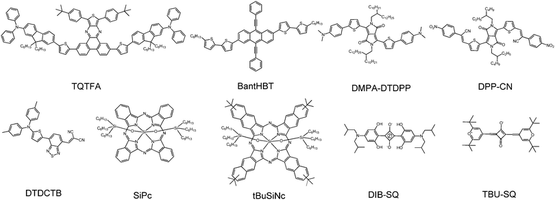 | ||
| Chart 3 The molecular structures of the third components (light-absorbing small molecules) used in OSCs. | ||
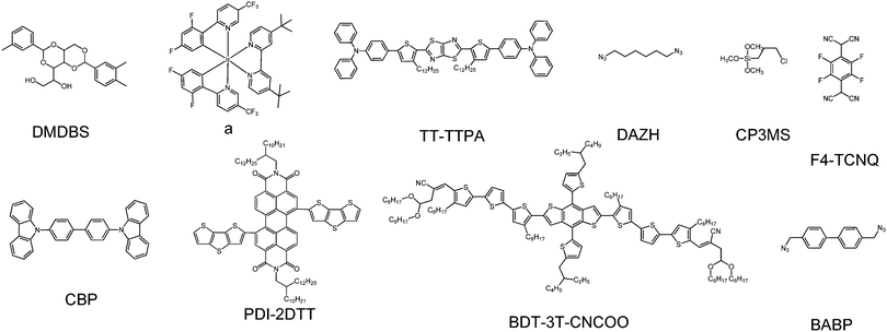 | ||
| Chart 6 The molecular structures of the third components (nonvolatile small molecule additives) used in OSCs. | ||
3.1. Donor/organic light-absorbing molecule/acceptor
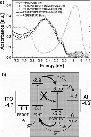 | ||
| Fig. 5 (a) Absorption spectra of thermally annealed layers of P3HT/PC61BM, PCPDTBT/PC61BM, and P3HT/PCPDTBT/PC61BM. (b) Energy levels of the electrodes and semiconductors used in the P3HT/PCPDTBT/PC61BM blends. The values for the organic semiconductors were determined by cyclic voltammetry.87 Reprinted with permission from ref. 87. Copyright 2010, Wiley. | ||
Poly[2,6-(4,4-bis-(2-ethylhexyl)-4H-cyclopenta[2,1-b;3,4-b0]-dithiophene)-alt-4,7-(2,1,3-benzothiadiazole)] (Si-PCPDTBT)105 exhibited much higher crystallinity and a lower bandgap than its counterpart PCPDTBT and accordingly was used to replace PCPDTBT as the third component in the OSCs.94–98 Incorporating 20% Si-PCPDTBT in P3HT/PC61BM led to a higher efficiency (4.0%) relative to the binary counterpart (3.1%). The JSC of the OSCs with a third component presented an approximate 30% increase relative to that of the binary blend OSCs, which was attributed to the higher Si-PCPDTBT ratio (20%).94 Ameri et al.97,98 used an indene-C60 bisadduct (ICBA)106 to replace PC61BM and fabricated P3HT/Si-PCPDTBT/ICBA OSCs. The efficiency increased to 5.1% due to the higher LUMO energy level of ICBA which produced a higher VOC of 0.79 V.
The structure of PCPDTBT and Si-PCPDTBT was completely different from that of P3HT. The ternary blend tended to separate into three phases, and the third component must have its HOMO and LUMO levels between the corresponding energy levels of P3HT and PCBM. This imposed a stringent requirement on the selection of the third component. Chemists introduced a new ternary blend approach of a “parallel-like BHJ” (PBHJ), in which two donor polymers with similar skeleton structures but different alkyl chains or substituent groups were used. These two polymer donors had good compatibility and different absorption spectra. In 2012, Yang et al.99 fabricated DTBT/TAZ/PC61BM OSCs. The polymers DTBT and TAZ had similar structures but different alkyl chains and substituent groups. After addition of 15% TAZ into a DTBT/PC61BM binary blend, the PCE of the OSCs increased from 4.39% to 5.88%. The absorption and external quantum efficiency (EQE) spectra of the PBHJ devices were essentially a linear combination of the spectra of their two “subcells” (Fig. 6a and c). Similarly, as shown in Fig. 6b and d, OSCs based on a DTPyT/DTffBT/PC61BM blend (25% DTffBT) exhibited an improved PCE (7.02%) relative to their binary counterpart (6.3%). In 2014, Lu et al.56 reported OSCs based on a PTB7/PID2/PC71BM blend. The third component, PID2, had a similar chemical structure to PTB7, while PID2 had a downshifted HOMO and LUMO relative to PTB7, leading to the formation of a cascade energy heterojunction. The larger bandgap of PID2 broadened the absorption of the blend films in the short wavelength region. In comparison with the binary blend OSCs based on PTB7/PC71BM, the OSCs based on PTB7/PID2/PC71BM demonstrated a higher PCE (8.22%). Recently, the same group changed the polymer donor and obtained a higher PCE of 9.20%.65
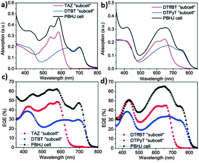 | ||
| Fig. 6 (a and b) Absorption spectra of the ternary blend devices and their “subcells” based on (a) TAZ/DTBT and (b) DTffBT/DTPyT. (c and d) EQE spectra of the ternary blend devices and their “subcells” based on (c) TAZ/DTBT and (d) DTffBT/DTPyT.99 Reprinted with permission from ref. 99. Copyright 2012, American Chemical Society. | ||
In order to investigate the relationship between the device efficiencies and the miscibility of the polymers (donor polymer and the third component) in ternary blend devices, Thompson and co-workers carried out some theoretical work.100–103 They studied two OSCs with a third component: P3HTT-DPP-10%/P3HT75-co-EHT25/PC61BM (with good miscibility of the two polymers) and P3HTT-DPP-10%/PCDTBT/PC61BM (with bad miscibility of the two polymers). The OSCs with good polymer miscibility showed tunability of VOC, which was explained by invoking an alloy model for the two polymer components. In this alloy model, optical excitation within the alloy was at the molecular level due to the highly localized nature of the exciton. The donor–acceptor interface and the corresponding interface bandgap (CT state), which determined VOC, displayed a material-averaged electronic structure due to the more delocalized nature of the one-electron states, and thus the VOC reflected the average composition of the interface.101 On the other hand, the OSCs with bad polymer miscibility did not show tunability of VOC. Unlike P3HTT-DPP-10% and P3HT75-co-EHT25, the structures of P3HTT-DPP-10% and PCDTBT were completely different and their surface energies were also highly different. The VOC was pinned to the smallest VOC of the corresponding binary blend, even at a P3HTT-DPP-10% content as low as 5%. The lack of miscibility and different surface energies between the polymers facilitated the preferential location of P3HTT-DPP-10% away from the PC61BM interface at high PCDTBT content and prevented the formation of an organic alloy, leading to a significant decrease in the device performance.102 The same group studied the electronic states of mobile carriers and excitons as well as the miscibility of the blend. Excitons originating from a dilute low-bandgap polymer in a polymer mixture diffused easily in the miscible system but not in the nonmiscible system, which was a consequence of their morphological and/or aggregation properties.103
Some other light-absorbing polymers were used as the third component to enhance the performance of OSCs.107–118 For instance, OSCs based on P3HT/THC8/PC61BM exhibited a better PCE (3.88%) compared with that of the binary blend (3.10%).107 The addition of 5% PTB7 enhanced the PCE from 2.93% to 4.07% in PCPDTBT/PC71BM-based OSCs.108 Very recently, Yang et al. improved the PCE of the PTB7/PC71BM blend from 7.2% to 8.7% by incorporating a NIR light-absorbing polymer PBDTT–SeDPP.55
In 2010, Huang et al.121 used a broad-bandgap (BBG) small molecule TQTFA to broaden the absorption of a P3HT/PC71BM blended film in the short wavelength region. After the addition of 11% TQTFA, the PCE of the devices increased from 3.90% to 4.50%. In 2013, Cha et al.122 employed a BBG small molecule BantHBT as the third component in OSCs. The strong absorption of BantHBT ranging from 300–600 nm, especially at 450 nm, was complementary with that of P3HT and PBTADN (Fig. 7a and b). The PCE of the P3HT/PC61BM-based devices increased from 3.0% to 3.7% with 9.1% of BantHBT incorporated. For the PBTADN/PC71BM system, the VOC, JSC, fill factor (FF) and PCE increased from 0.83 V, 6.9 mA cm−2, 0.53 and 3.0% to 0.91 V, 11.0 mA cm−2, 0.56 and 5.6%, respectively, after the addition of 4.8% BantHBT. The third component BantHBT not only increased the absorption of the active layer, but also displayed good miscibility with the polymer donors, and balanced the charge transport.
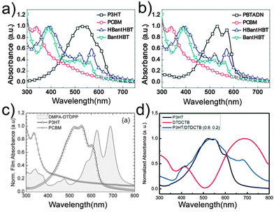 | ||
| Fig. 7 UV-visible absorption spectra of (a) P3HT, PC61BM, HBantHBT and BantHBT films,122 (b) PBTADN, PC71BM, HBantHBT, and BantHBT films,122 (c) DMPA-DTDPP, P3HT and PC61BM films,123 and (d) P3HT, DTDCTB and P3HT/DTDCTB films,125 respectively. Reprinted with permission from ref. 122. Copyright 2013, Wiley. Reprinted with permission from ref. 123. Copyright 2012, Wiley. Reprinted with permission from ref. 125. Copyright 2014, American Chemical Society. | ||
Compared with BBG small molecules, the use of LBG small molecules as the third component in OSCs was more popular.123–130 Lee et al.123 fabricated OSCs based on P3HT/DMPA-DTDPP/PC61BM. DMPA-DTDPP was a LBG small molecule based on the diketopyrrolopyrrole (DPP) unit and broadened the absorption of P3HT/PC61BM (Fig. 7c). The PCE of devices increased from 3.02% to 3.37% with the use of DMPA-DTDPP. Sharma et al.124 added DPP-CN as the third component in a P3HT/PC71BM blended film to fabricate OSCs. The photosensitivity in the wavelength region from 620 to 750 nm was improved, and JSC was enhanced from 9.40 mA cm−2 to 10.9 mA cm−2. As a result, the PCE was improved from 3.23% to 4.37%. Ye et al.125 fabricated OSCs based on P3HT/DTDCTB/PC61BM, in which the absorption edge of the third component DTDCTB was >800 nm (Fig. 7d). After the addition of 10% DTDCTB, the PCE of the OSCs increased to 4.07%, better than that of the binary blend OSCs (3.25%).
Förster resonance energy transfer (FRET) was a promising strategy to improve exciton migration over long distances and reduce energy loss. Employing dye molecules which have a large spectral overlap between their absorption and the emission of the donor as the third component was a new way to utilize FRET. These dye molecules had a high absorbance in the red and NIR spectral regions. Some LBG small molecule dyes, which had a narrow and strong absorption that overlapped with the emission band of donor materials, were used as the third component in OSCs. In 2009, Honda et al.131 used silicon phthalocyanine bis(trihexylsilyl oxide) (SiPc) as the third component in P3HT/PC61BM; their energy levels were suitable to form a cascade energy heterojunction (Fig. 8a). The absorption peak of SiPc was around 680 nm, and overlapped with the emission peak of P3HT (Fig. 8b). After the addition of SiPc to the P3HT/PC61BM blend, the PCE increased from 2.2% to 2.7%. Later, the same group investigated the morphology of this OSC with the third component.132–134 After the optimization of the device conditions and the ratio of SiPc in OSCs, the VOC, JSC, FF and PCE increased to 0.58 V, 11.1 mA cm−2, 0.65 and 4.2% respectively, which were higher than those of the binary blend.132 As shown in Fig. 8c, the light harvesting based on the dye sensitization and the polymer exciton harvesting were highly efficient because the SiPc molecules were selectively localized at the polymer/fullerene interface (interfacial coverage around 40%). In particular, the SiPc molecules were closely in contact with both P3HT and PC61BM at the interface instead of forming aggregations (bulky groups suppress the formation of dye aggregations), which was an ideal interfacial structure for the efficient cascade energy heterojunction.133
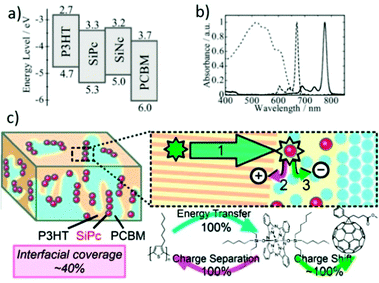 | ||
| Fig. 8 (a) Energy diagrams of P3HT, PC61BM, SiPc, and SiNc, (b) absorption spectra of the P3HT/PC61BM film (dotted line), SiPc (dashed line), and SiNc (solid line) in solution.134 (c) Schematic diagram of the morphology, energy transfer and charge transfer of P3HT/SiPc/PC61BM films.133 Reprinted with permission from ref. 134. Copyright 2010, Royal Society of Chemistry. Reprinted with permission from ref. 133. Copyright 2011, American Chemical Society. | ||
Silicon naphthalocyanine bis(trihexylsilyloxide) (SiNc)134 was also introduced as the third component in OSCs because of its narrower bandgap and red-shifted absorption relative to SiPc (Fig. 8a and b). However, due to the limited solubility of the SiNc dye, the PCE did not exhibit an obvious enhancement after the addition of the third component. The PCEs of the OSCs with 1.5% SiNc and the binary blend OSCs were 3.7% and 3.5%, respectively. In 2014, Lim et al.135 employed a modified dye molecule, tBuSiNc, as the third component in OSCs. The t-butyl groups improved the solubility, which allowed more dye incorporation. The P3HT/PC61BM device incorporating 8% tBuSiNc exhibited a higher efficiency of 4.46% compared to the binary blend OSCs (3.80%).
Squaraine (SQ)-based small molecules were also widely used dyes as the third component in OSCs.136–140 In particular, DIB-SQ was the most representative SQ molecule used as the third component in OSCs.136–138 In 2013, Huang et al.137 used DIB-SQ in a P3HT/PC61BM system to fabricate OSCs. DIB-SQ had suitable energy levels which could form a cascade energy heterojunction with P3HT/PC61BM (Fig. 9a) and its absorption overlapped with the emission spectrum of P3HT (Fig. 9b). In comparison with the control devices, the device with 0.5% DIB-SQ exhibited a significant increase of 38% in PCE due to the improved JSC and FF. Compared with DIB-SQ, TBU-SQ exhibited a red-shifted absorption peak from 650 to 710 nm, which had a better overlap with the emission spectrum of P3HT.139 The PCE of devices increased from 3.47% to 4.55% after the addition of 2.5% of the third component TBU-SQ. Thermal annealing of the P3HT/TBU-SQ/PC71BM OSCs further increased the PCE to 5.15%. In addition to the widely used SiPc, SiNc and SQ-based dye molecules, other dyes such as BODIPY were also introduced as the third component in OSCs to achieve a higher PCE.141–145
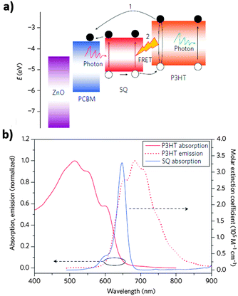 | ||
| Fig. 9 (a) Energy level diagram of the components in an OSC highlighting pathways for charge generation, (b) extinction coefficient of SQ in 1,2-dichlorobenzene, and the absorption and emission spectra of a P3HT film.137 Reprinted with permission from ref. 137. Copyright 2013, Nature Publishing Group. | ||
3.2. Donor/acceptor/acceptor
Electron acceptor materials were also used as the third component in OSCs (Chart 4). In the last decade, a mass of acceptor materials were developed including fullerene derivatives146–148 and non-fullerene molecules.149–153 Some of these molecules had up-shifted LUMO and HOMO levels compared to PCBM, resulting in a cascade energy heterojunction with a donor polymer and PCBM; some of them were chemically modified to form a buffer layer or enhance the device stability (Table 3).ICBA106 was the most representative third component in donor/acceptor/acceptor ternary blends and used for the formation of a cascade energy heterojunction. In 2011, Khlyabich et al.154 fabricated OSCs using P3HT as a donor and two soluble fullerenes, PC61BM and ICBA, as acceptors. The VOC of the ternary blend OSCs could be tuned between the limiting VOC values of the corresponding binary blend (P3HT/PC61BM, P3HT/ICBA) solar cells. Recently, Cheng et al.57 used ICBA as an electron-cascade acceptor material (the third component) in PTB7/PC71BM blends to fabricate OSCs. Due to the higher LUMO energy level of ICBA relative to PC71BM, the VOC increased with the addition of ICBA. ICBA played a bridging role between PTB7 and PC71BM (cascade energy heterojunction), thus providing more routes for charge transfer at the D/A interface. As shown in Fig. 10, the morphology of the blend films with a third component was similar to that of PTB7/PC71BM when the ICBA content was much lower than the PC71BM content which guaranteed suitable phase separation and efficient charge transport. However, a higher ICBA content would destroy the morphology. Compared with the binary blend of PTB7/PC71BM, the devices with 9% ICBA content exhibited enhanced VOC, JSC, FF and PCE values. The highest PCE of this OSC with a third component was 8.24%, which was the highest reported for ternary blend OSCs and ICBA-related OSCs. Recently, the same group promoted the PCE to 8.88% by use of the method of diluting a concentrated solution.63
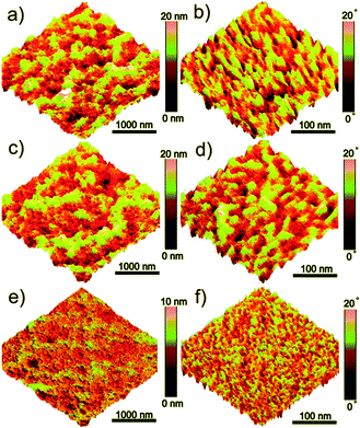 | ||
| Fig. 10 Atomic force microscopy (AFM) height images (a, c and e) and phase images (b, d and f) of PTB7/ICBA/PC71BM films spin-coated on ITO/PEDOT:PSS substrates: (a, b) 0% ICBA, (c, d) 9% ICBA, and (e, f) 18% ICBA.57 Reprinted with permission from ref. 57. Copyright 2014, Royal Society of Chemistry. | ||
In addition to ICBA, some other fullerene-based acceptors were also used as the third components in OSCs to achieve better efficiency.155–161 For instance, Kang et al.155 fabricated OSCs based on P3HT/OXCTA/OXCMA; the device incorporating 11.3% OXCTA exhibited an efficiency of 3.96%, higher than that of its binary counterpart (3.61%). Santo et al.156 and Ko et al.157 improved the PCEs of P3HT and PTBT-based OSCs by using a mix of PC61BM and PC71BM as acceptors. Chen et al.159 used PCBPy as the third component in OSCs. PCBPy could self-organize into nanostructures to control the morphology; the PCE of P3HT/PC61BM-based OSCs was significantly improved to 4.8%.
In addition to their use in the formation of a cascade energy heterojunction, fullerene acceptor molecules were used to form a buffer layer or a desired vertical phase separation. Wei et al.162 introduced a fluorocarbon chain-modified fullerene acceptor, F-PCBM, in a P3HT/PC61BM blend. F-PCBM had a lower surface energy compared with P3HT and PC61BM. The addition of a small amount (5.3%) of F-PCBM improved the photovoltaic performance due to the spontaneous formation of the thin buffer layer at the top surface of the active layer. On the other hand, some fullerene acceptor materials with a high surface energy can also be used as the third components in OSCs. Ma et al.163 employed an amino-containing fullerene derivative PCBDAN as the third component in a P3HT/PC61BM blend to fabricate inverted OSCs. Due to its higher surface energy relative to P3HT and PC61BM, PCBDAN served as the cathode interfacial material at the bottom and decreased the work function (WF) of ITO for its use as the cathode.
Fullerene derivatives with a spherical geometry tended to diffuse out of the blend and aggregate into larger clusters. In order to suppress the aggregation and improve the morphology stability, some fullerene derivatives with chemical modification were used as the third component in OSCs. In 2011, Cheng et al.164 employed the fullerene derivatives PCBSD and PCBS in a P3HT/PC61BM blend to improve the morphology stability, since PCBSD and PCBS suppressed the severe migration of PC61BM. After adding a small amount (8.3%) of PCBSD into the P3HT/PC61BM blend, the morphology stability of the blend was improved. In 2014, the same group84 synthesized a fluorine-modified fullerene derivative PC61BPF, and used it as the third component in OSCs. The merit of PC61BPF was to impart a complementary attraction between the pentafluorophenyl group of PC61BPF and the C60 cores of PC61BPF/PC61BM. Such a supramolecular interaction could effectively suppress the aggregation of PC61BM and improve the morphology stability. By adding 10% PC61BPF, the PDTBCDTBT/PC61BPF/PC71BM device yielded a PCE of 4.24% after heating at 150 °C for 25 h, preserving 81% of its original value. In sharp contrast, the PCE of the device using a traditional PDTBCDTBT/PC71BM blend decayed drastically to 0.19% over 25 h of heating. Similarly to this strategy, Schroeder et al.165 improved the morphology stability of polymer/fullerene OSCs by incorporating a PC61BM dimer ((PCB)2C2) as the third component. After the use of 10% (PCB)2C2 in OSCs, the PCE was higher and the morphology stability was much better. Some groups also improved the thermal stability of OSCs by using crosslinkable fullerene derivatives as the third component.166–168
In addition to fullerene acceptors, non-fullerene acceptors were also used as the third component in donor/acceptor/acceptor OSCs. For example, Andrew et al.169 added DCF1 or DCF2 to a P3HT/PC61BM blend as the third component. These two compounds had suitable energy levels and could form a cascade energy heterojunction with P3HT/PC61BM. After the addition of 33% DCF1 or DCF2 in the P3HT/PC61BM blend, the PCEs of both P3HT/DCF1/PC61BM and P3HT/DCF2/PC61BM OSCs increased to 3.7%, which was higher than that of the P3HT/PC61BM control device. Some ambipolar molecules were also used as the third component in OSCs.170–174
3.3. Donor/inorganic nanomaterial/acceptor
Gold (Au)-based179–183 nanomaterials were widely used in OSCs as the third components to achieve stronger light absorption and a higher efficiency. Paci et al.179 reported OSCs based on P3HT/Au nanoparticles (Au NPs)/PC61BM. The device incorporating 5% Au NPs exhibited a higher efficiency of 3.71% compared to that of the control device (3.26%). The Au NPs were also used in an amorphous polymer donor/PCBM blend; for example, Wang et al.180 employed Au NPs in a PCDTBT/PC71BM blend as the third component and the PCE was improved from 5.77% to 6.45%. This improvement resulted from a combination of enhanced light absorption caused by the light scattering of Au NPs in the active layer and the plasmon-induced light concentration at specific wavelengths.
Silver (Ag)-based184–189 nanomaterials were also widely used in OSCs as the third component. These nanomaterials had a lot of geometric constructions. For instance, Kim et al.184 used Ag NPs or Ag nanowires (NWs) (Fig. 11a) in a P3HT/PC61BM blend. Both the Ag NPs and Ag NWs enhanced the absorption of the active layer in its original absorption region. Compared with P3HT/PC61BM solar cells, the P3HT/Ag NPs/PC61BM and P3HT/Ag NWs/PC61BM OSCs had nearly the same VOC, and a reasonably higher JSC, FF, and PCE. Li et al.185 fabricated OSCs based on Ag NPs (Fig. 11b) or Ag nanoprisms (Fig. 11c). After the addition of Ag nanoprisms to a P3HT/PC61BM blend, the PCE increased from 3.60% to 4.07% (for Ag NPs, the PCE was 3.99%). Due to the improved overlap between the absorption spectra of the active layer material and the Ag nanoprism, the high-order resonances contributed a lot to the absorption enhancement of the OSCs. Lee et al.186 employed Ag-based core–shell nanoparticles (Fig. 11d) in OSCs as the third component. As the surface of the Ag NPs was modified by introducing a SiO2 layer and an oligothiophene (OT) derivative, the resulting Ag@SiO2–OT NPs became miscible with the P3HT/PC61BM blend without aggregation, leading to a large enhancement (18%) in the PCE value compared to the pristine P3HT/PC61BM device. The same concept of a core–shell nanostructure was also used in Au-based nanoparticles. Xu et al.49,54 used Au@SiO2 as the third component in a 7,7′-(4,4-bis(2-ethylhexyl)-4H-silolo[3,2-b:4,5-b′]-dithiophene-2,6-diyl)bis(6-fluoro-4-(5′-hexyl-[2,2′-bithio-phen]-5yl)benzo[c][1,2,5]-thiadiazole) (p-DTS(FBTTh2)2)/PC71BM blend. Due to the plasmonic and scattering effects caused by the Au NPs, the PCE of OSCs with a third component (8.11%) was much higher than that of the control device (6.52%).
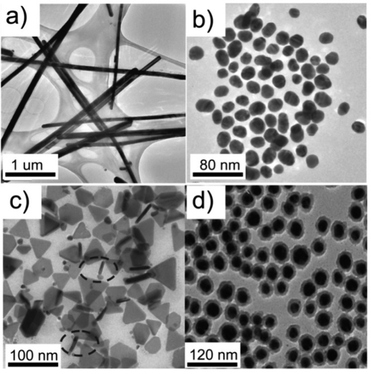 | ||
| Fig. 11 Transmission electron microscope (TEM) micrographs of (a) Ag NWs,184 (b) Ag NPs, (c) Ag nanoprisms,185 and (d) Ag@SiO2–OT NPs.186 Reprinted with permission from ref. 184. Copyright 2011, American Chemical Society. Reprinted with permission from ref. 185. Copyright 2013, Wiley. Reprinted with permission from ref. 186. Copyright 2014, Royal Society of Chemistry. | ||
In addition to Au or Ag-based nanomaterials, a platinum–nickel (Pt–Ni) nanomaterial52 was also used as the third component. Recently, Chou et al.52 employed Pt–Ni multipods (MPs) in PBDTTT-C-T/PC71BM-based solar cells and the PCE was improved from 7.38% to 8.48%. The MPs were an excellent scattering center to improve light absorption, conductivity and charge transport.
Some special QDs were also used in OSCs and showed good performance.205–209 For instance, Li et al.207 employed CdS QD-sensitized TiO2 nanotube arrays (CdS/TNTs) as the third component in a P3HT/PC61BM blend. The CdS/TNTs were synthesized using the chemical bath deposition (CBD) method and dispersed in the P3HT/PC61BM layer, which not only increased the light absorption but also reduced the charge recombination. As a result, a high PCE of 3.52% was achieved for the OSCs (incorporating 2.7% CdS/TNTs), which was a 34% increase compared with the P3HT/PC61BM devices. In 2013, Li et al.208 fabricated three-component OSCs using graphene quantum dots (GQDs) as the third component. The GQDs were synthesized from double walled carbon nanotubes (DCNTs) with a uniform size distribution (3–5 nm). The JSC (24.6 mA cm−2) and PCE (4.35%) of the OSCs based on the P3HT/GQDs/PC61BM blend were significantly improved compared with those of the P3HT/PC61BM device (14.3 mA cm−2 and 2.61%). This improvement was attributed to the enhanced absorption of the blended film and the suitable energy level structure of the GQDs (cascade energy heterojunction).
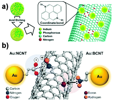 | ||
| Fig. 12 (a) Chemical interaction for the QD:NCNT nanohybrid formation.215 (b) Schematic chemical interactions for Au:NCNT (left) and Au:BCNT (right) hybrids.53 Reprinted with permission from ref. 215. Copyright 2013, Wiley. Reprinted with permission from ref. 53. Copyright 2015, Wiley. | ||
Graphene can promote more efficient charge-carrier transport compared with CNTs, and was also used in OSCs as the third component.220–222 For instance, Jun et al.220 fabricated OSCs based on P3HT/N-doped reduced graphene oxide (N-RGO)/PC61BM. The N-RGO was well dispersed in the polymer matrix and enhanced the electron transport properties due to its high carrier mobility and charge selectivity. Compared with the control device, the JSC and PCE of the OSCs using N-RGO (0.5%) increased significantly from 10.4 mA cm−2 and 3.2% to 15.0 mA cm−2 and 4.5%, respectively.
3.4. Donor/organic nonvolatile additive/acceptor
Block copolymers were used to improve the morphological stability of immiscible material blends, and were described as a compatibilizer in OSCs.223,224 The interfacial energy between the immiscible components decreased, as the block copolymer compatibilizers were preferentially located at the interface of the immiscible materials to span the heterojunction itself, consequently ensuring good miscibility in the systems.225 In the last 5 years, various block copolymer compatibilizers were synthesized and used as the third component in OSCs.226–241 Block copolymers with a rod–coil structure were the most widely used polymer additives. Han et al.226 used an asymmetric rod–coil block copolymer P3HT-b-PTMSM in a P3HT/PC61BM blend to form a passivation layer between the microscopically phase-separated D/A domains. As shown in Fig. 13, the P3HT (rod) crystallized and phase-separated from the PC61BM domains, while the PTMSM blocks (coil) were localized in the interfacial region between the P3HT and PC61BM domains. Thermal condensation of the trimethoxysilyl groups of the PTMSM blocks yielded a SiOx-like interfacial passivation layer to depress the local shunts and efficiently blocked the injection of holes into the leakage pathway, thus the recombination of charge carriers was suppressed. The incorporation of 5% P3HT-b-PTMSM in the active layer effectively enhanced the charge transport and increased the PCE from 2.6% to 3.7%. Renaud et al.227 employed P3HT-b-P4VP in a P3HT/PC61BM blend to control the morphology of the active layer. After the addition of 3.8% P3HT-b-P4VP, the JSC and PCE increased from 9.0 mA cm−2 and 2.7% to 12.2 mA cm−2 and 4.3%, respectively. The better performance of OSCs with compatibilizers was related to the formation of a well-optimized nanoscale structure that allowed for more efficient exciton dissociation and charge transport, by lowering the charge recombination and/or trapping. Sun et al.228 used PS-b-P3HT as a polymer additive in P3HT/PC61BM based OSCs. The interaction between the polystyrene (PS) segments and PC61BM was a major driving force to control phase separation in the P3HT/PC61BM blend. The PS-b-P3HT induced a favourable active layer morphology with interpenetrating nanoscale domains, and the enhanced P3HT crystallinity and orientation facilitated hole transport within the active layer. Moreover, the addition of the PS-b-P3HT compatibilizer affected the PC61BM segregation in the vertical direction, in which the PC61BM accumulation near the substrate interface was reduced, with a corresponding increase in the middle region of the active layer. The PCE of the OSCs with compatibilizers was 4.11%, which was higher than that of the control device (3.25%).
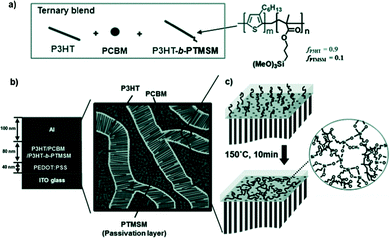 | ||
| Fig. 13 Generation of silica-containing passivation layers embedded in the interfacial region of P3HT/PC61BM domains using a block copolymer: (a) the formation of a ternary blend with the addition of the P3HT-b-PTMSM block copolymer. (b) A schematic representation of the phase-separated morphology of a P3HT/P3HT-b-PTMSM/PC61BM blend. (c) Thermal cross-linking of PTMSM domains to form a silica-containing layer in the P3HT/PC61BM interface. Note that one among several P3HT chains contains a PTMSM tail.226 Reprinted with permission from ref. 226. Copyright 2012, Wiley. | ||
Some liquid crystalline segments can also be used as one block in P3HT-based compatibilizers. Yuan et al.229 employed a self-assembled liquid crystalline rod–coil block copolymer P3HT-b-PTP in P3HT/PC61BM-based OSCs; the PCE was increased from 3.24% to 4.03%. The self-assembly of liquid crystalline blocks (much stronger after thermal annealing to form the liquid crystalline states), the interaction between the P3HT block in the compatibilizer and the chains of the P3HT donor, and the liquid crystalline copolymer located at the interface of the donor and the acceptor induced a long range crystallinity of the P3HT domains and the formation of interpenetrating networks, which resulted in improved charge transport. For polymer/fullerene OSCs, to improve the miscibility between the donor and acceptor, block copolymers with fullerene as a pendant group were used as the compatibilizer in ternary blends. Chan et al.230 synthesized a block copolymer C60-BCP and used it as the third component in OSCs. After the addition of 16.7% C60-BCP, the PCE of the P3HT/C60-based OSCs had a large enhancement from 0.48% to 2.56%. Mixing P3HT with C60-BCP induced the formation of a self-organized nanostructure and enhanced the interchain interactions in the P3HT domain. C60-BCP induced a moderate phase-separated morphology with crystalline P3HT and C60 domains in the active layer, which was the key to a higher JSC value (increased from 1.9 mA cm−2 to 9.0 mA cm−2) because it benefited both charge separation and charge transport.
In addition to controlling the horizontal phase separation of the active layer, the polymer additives can also induce more efficient vertical phase separation; they can self-organize to form hole or electron buffer layers. Jung et al.242 added PEG-C60 to the P3HT/PC61BM blend. The PEG-C60 molecules migrated to the top surface of the P3HT/PC61BM active layer and induced the segregation of PC61BM near the top surface, which formed an ideal vertical distribution of PC61BM in the active layer (Fig. 14). When 2.4 wt% of PEG-C60 was used, the performance of OSCs was largely enhanced. The increase of VOC upon the addition of PEG-C60 was due to the generation of the interfacial dipole moment and the vacuum level shift of the metal cathode; the enhanced FF suggested that an ideal vertical morphology in the active layer was well developed. Furthermore, since the PEG-C60 layer protected the active layer from oxygen penetration, as well as from the invasion of aluminium (Al) into the active layer during metal deposition, the stability of the OSCs was improved. Shi et al.243 used a block copolymer with a lithium ion (Li+) (P3HT-b-P3TEGT:Li+) in a P3HT/PC61BM blend as the third component. Due to the spontaneous vertical migration of P3HT-b-P3TEGT:Li+ to the surface of the active layer during the spin-coating process and the formation of a self-assembled anode buffer layer (inverted structure), a vertical distribution of components in the active layer and an ordered arrangement of donor polymer chains were obtained at the same time. In addition, the self-assembled anode buffer layer could provide the interfacial modification between the active layer and the anode electrode, increase the WF of the anode electrode, increase the electrical conduction of the device, and consequently remarkably improve the device performance and stability. After the addition of 1.9% P3HT-b-P3TEGT:Li+, the PCE of the OSCs increased from 1.6% to 3.6%.
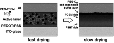 | ||
| Fig. 14 Schematic illustration of a bulk heterojunction solar cell with PEG-C60 as the buffer layer.242 Reprinted with permission from ref. 242. Copyright 2011, Wiley. | ||
Insulating polymers were another series of polymer additives and can improve the film-forming properties and control the film morphology.251–257 Huh et al.251 used poly(oxyethylene tridecyl ether) (PTE) surfactant as the third component in a PCDTBT/PC71BM blend. A high PCE (6.1%) was obtained for OSCs by the use of a 6.7% PTE additive. This improvement in the PCE may be attributed to the increased selective flow of dissociated charge carriers; not only at the interfaces between the active layer and the electrodes, but also at the D/A interface. Huang et al.58 added a small amount of high molecular weight PS to a p-DTS(FBTTh2)2/PC71BM blend as the third component. The addition of PS increased the solution viscosity at low concentrations and led to an increase in the film thickness of the small molecule blend, control over the dewetting and uniformity of the film, and a desirable adjustment of the active layer morphology. Because of the favourable interaction between PS and the solvent, the film may retain the solvent for longer, which enhanced the crystallization of p-DTS(FBTTh2)2 and the evolution of individual phases of p-DTS(FBTTh2)2 and PC71BM. The PCE of the small molecule OSCs increased from 7.1% to 8.2% after the use of 2.5% PS. Also for the optimization of small molecule OSCs, Zhou et al.59 employed poly(dimethylsiloxane) (PDMS) as the third component in OSCs. The PDMS could control the morphology of the active layer and enhanced the PCE of DR3TBDTT/PC71BM small molecule OSCs from 7.51% to 8.12%. The addition of an insulating polymer in a non-negligible amount showed benefits for OSCs, with the prospect of cost-effective module manufacture and mechanical stability.223 Ferenczi et al.255 used high density polyethylene (HDPE) in a P3HT/PC61BM blend as the third component. After the addition of HDPE (up to ≈50%), the photovoltaic properties of P3HT/PC61BM OSCs were not seriously decreased, which suggested the feasibility of cost-effective module manufacture. HDPE could assist the deposition process and reduce the occurrence of defects in the films, thus offering a high manufacturing yield over a large area.
Some of the nonvolatile small molecule additives were used to control the horizontal and vertical phase separation.262–276 As some representative examples, Kim et al.262 employed a fractional amount of nonvolatile additives (a) in a P3HT/PC61BM blend and the PCE was improved. This additive, selectively partitioned into P3HT due to its special hydrophobicity, effectively enhanced the phase separation between the electron donor and acceptor phases. Farahat et al.264 used a silicon based small molecule additive CP3MS in the SMDPPEH/PC61BM blend. The PCE increased from 2.75% to 4.55% after the addition of 0.1% CP3MS. This nonvolatile additive was a morphological controller and also could form an ultrathin buffer interlayer between the Al cathode and the active layer by self migration (Fig. 15). Cheng et al.265 fabricated OSCs based on P3HT/TT-TTPA/PC61BM, in which TT-TTPA had good miscibility with PC61BM. During solvent annealing and thermal annealing, the small amount of TT-TTPA in the P3HT domains could move from the P3HT domains to the PC61BM domains, thus increasing the phase purity of the P3HT domains that can undergo crystallization. After the addition of 3.8% TT-TTPA in the P3HT/PC61BM blend, a better PCE (4.41%) was achieved relative to the binary blend (3.85%). Qin et al.266 employed CBP as the third component in a P3HT/PC61BM blend. The phase separation of P3HT and PC61BM was altered by adding a small amount of crystalline CBP (1.6%) due to the difference in the surface energy of P3HT and CBP. After the use of CBP, the PCE of the OSCs was increased from 1.43% to 1.85%. Zhang et al.60 fabricated OSCs based on PBDTTPD-HT/BDT-3T-CNCOO/PC71BM. The optimal content of BDT-3T-CNCOO (20%) resulted in the formation of favourable nanostructures for charge generation and collection. The OSCs with a third component yielded a high PCE of 8.40%, which was higher than the binary systems based on small molecule/fullerene (7.48%) and polymer/fullerene (6.85%). Recently, the same group increased the PCE of this type of OSCs to 10.5%.64
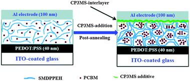 | ||
| Fig. 15 Schematic representation of the dual function of the additive CP3MS when combined with a post-annealing treatment.264 Reprinted with permission from ref. 264. Copyright 2014, Royal Society of Chemistry. | ||
Nonvolatile small molecule additives were also used in all-polymer solar cells. All-polymer solar cells, which consist of a polymer donor and a polymer acceptor, have attracted considerable attention in the last decade due to their advantages over polymer/fullerene solar cells.153,277,278 In 2014, Cheng et al.267 used a nonvolatile small molecule additive, PDI-2DTT, as the third component in a PBDTTT-C-T/PPDIDTT blend. PDI-2DTT had a similar chemical structure to that of the polymer acceptor PPDIDTT, which could suppress the aggregation of PPDIDTT and facilitate its mixing with the polymer donor PBDTTT-C-T. After the incorporation of 1% PDI-2DTT, the PCE of all-polymer solar cells was increased from 3.04% to 3.45%. Recently, the same group employed the inverted structure in these all-polymer solar cells with PDI-2DTT additives and achieved PCEs of 3.505% and 0.727% with a spin-coated process and a roll-coated process, respectively.279
In addition to adjusting the phase separation, nonvolatile small molecule additives had some other functions.280–285 For example, Rumer et al.281 used a dual function additive (the small molecule crosslinker DAZH) to simultaneously enhance the PCE and stability of SiIDT-BT/PC71BM solar cells. A 2.2% bis-azide DAZH additive increased the device efficiency from 6% to 7%. Moreover, the OSCs with a third component preserved 85% of their initial PCE after 130 h heating at 85 °C (control device: 60% preserved). As shown in Fig. 16, the addition of DAZH greatly suppressed fullerene crystallization. Furthermore, the BHJ microstructure had a fibrillar character, as observed by AFM, as a result of frustrated fullerene aggregation and suppressed polymer skin formation at the cathode. Derue et al.86 employed a bis-azide cross-linking reagent (BABP) as the third component in OSCs. This nonvolatile small molecule additive could stabilize the morphology of the active layer by preventing the fullerenes from diffusing and forming large crystallites. As shown in Fig. 17, long time thermal annealing induced PC61BM aggregation and a large size phase separation of the PTB7/PC61BM film, but the morphology of the PTB7/BABP/PC61BM film was not changed after a long thermal annealing time. By adding 2% BABP, the PTB7/BABP/PC61BM device yielded a PCE of 4.60% after 16 h of heating at 150 °C, preserving 80% of its original value. In sharp contrast, the PCE of the device using a PTB7/PC61BM blend decayed drastically to 16% over 16 h heating at 150 °C. Zhang et al.282 used a small molecule F4-TCNQ as the third component in PCDTBT/PC71BM solar cells to increase the photoconductivity of the active layer. Under low doping concentrations (0.4%), the photocurrent in the PCDTBT/PC71BM solar cells exhibited a considerable increase from 11.0 mA cm−2 to 14.0 mA cm−2 due to the improved hole mobility, leading to an ultimate enhancement of the PCE from 6.41% to 7.94%.
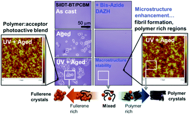 | ||
| Fig. 16 Crosslinking and thermal ageing morphology: small molecule additives confer macrostructure thermal stability, through suppressed fullerene crystallization (central optical microscopy images), with the bis-azide DAZH additionally enhancing the microstructure through fibril formation (flanking AFM images). Such a “double” picture of morphology highlights the various donor–acceptor phases in bulk heterojunctions and the microstructural basis of stability.281 Reprinted with permission from ref. 281. Copyright 2015, Wiley. | ||
 | ||
| Fig. 17 Optical microscopy images (scale bar: 50 μm) of a PTB7/PC61BM BHJ solar cell: (a) before thermal annealing and (b) after thermal annealing at 150 °C for 16 h without cross-linker. Numerous micrometer-sized PC61BM crystals were observed. (c) Image of the same blend with the addition of BABP after thermal annealing at 150 °C for 16 h, indicating the absence of microcrystals.86 Reprinted with permission from ref. 86. Copyright 2014, Wiley. | ||
4. The reasons for the better performance of three-component OSCs
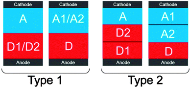
OSCs with a third component generally had better performance compared with their control devices. Some of them had higher VOC, JSC or FF values which enhanced the PCE; some of them had better morphology stability which increased the durability. Reasons for the improvements are summarized below.A higher VOC of the OSCs can be achieved in two ways using the third component. The first one was to introduce a second donor with a lower HOMO energy level (D2) or a second acceptor with a higher LUMO energy level (A2) as the third component in the OSCs, and to form some kind of ternary phase separation. As in type 1 in Fig. 18, two donors (or two acceptors) blended with each other (good miscibility and similar surface energies) and contacted with the anode (or cathode). In this type, some holes (or electrons) were extracted by the anode (or cathode) from the HOMO of D2 (or the LUMO of A2), which increased the VOC of the OSCs. The other way was to introduce the third component which can self-organize to form the hole (or electron) transport interlayer between the anode (or cathode) and the active layer. The self-organized interlayer can significantly increase the VOC because it can generate the interfacial dipole and shift the vacuum level of the anode or cathode (i.e. increase the WF of the anode electrode or decrease the WF of the cathode electrode).
A higher JSC of OSCs with a third component was attributed to a stronger and broader absorption and efficient charge transfer, charge transport and charge extraction. Some kinds of third components (organic light-absorbing polymers and molecules) can broaden the absorption of the binary blend at the short wavelength or long wavelength region, since they have a strong absorption which is complementary with the absorption of the host donor and acceptor material. Some kinds of third components (metal nanomaterials and quantum dots) can enhance the absorption of the binary blend by LSPR effects or quantum effects. The broader or stronger absorption caused by these third components can increase JSC. Charge transfer was also very important for JSC. As shown in Fig. 18 (type 2), by the introduction of D2 (or A2) as a cascade energy material in OSCs and the formation of some kind of ternary phase separation, the third component was located at the D/A interfaces and did not contact with the anode (or cathode). Some holes were transferred by the A–D2–D1 (or A1–A2–D) route, while electrons were transferred by the D1–D2–A (or D–A2–A1) route, both of which induced efficient charge transfer and thus increased the JSC of the OSCs. Efficient charge transport was another important factor in achieving a higher JSC. Third components with a high hole or electron mobility (e.g. carbon-based nanomaterials) can obviously increase the charge transport properties as they provided extra charge transport pathways. Some organic third components can optimize the molecular arrangement (e.g. enhance the crystallinity of the donor or acceptor), purify the donor or acceptor domains so that the charge recombination traps were reduced, and optimize the D/A interfaces. The charge transport properties and JSC can be significantly improved after the use of these third components. The efficient vertical phase separation induced by some third components can also enhance JSC due to the improved charge extraction at the right electrodes (holes extracted by the anode and electrons extracted by the cathode).
Some third components (e.g. block polymer compatibilizers) can improve the FF of OSCs as they can increase the hole or electron mobility due to the formation of more efficient charge transport pathways, balance the hole and electron transport, and/or induce efficient charge extraction at the right electrodes. After the use of these third components, the energy loss in the charge transport and extraction of the OSCs was significantly reduced, leading to an increase in the FF. Given the fact that the typical exciton diffusion length in a disordered blend layer is about 10 nm, the third component can control the phase separation of the donor and acceptor to ca. 10 nm to reduce the energy loss during exciton diffusion, which can increase the FF.
Better morphology stability was achieved in OSCs with a third component because some third components can suppress the aggregation of the fullerene acceptor and freeze the morphology of the active layer. These third components had a supramolecular interaction with the fullerene acceptor, or crosslinked the fullerene acceptors before their excessive aggregation. Thus, these OSCs with a third component had much better morphology stability and showed great potential for future industrial manufacture.
5. Summary and outlook
Adding a third component is an emerging and promising strategy towards high-performance OSCs and presents some advantages: broader and stronger absorption, more efficient charge transfer, more efficient charge transport pathways, better charge extraction at the electrodes and improved stability. Various types of third components such as light-absorbing small molecules or polymers, fullerene or non-fullerene acceptors, metal or carbon-based nanomaterials, quantum dots, and polymer or small molecule nonvolatile additives were added to OSCs. In order to promote this research field and achieve a higher performance of OSCs, some fundamental research may deserve further attention in the future: (a) the synthesis of new light-absorbing materials with a strong absorption, which is complementary with the absorption of the host donor and acceptor materials; (b) the control of the ternary phase separation to enhance both VOC and JSC; (c) the introduction of some molecular interactions to build ideal nanostructures in the active layer (e.g. a self-organized interlayer, unrestricted charge transport pathways, frozen morphology); (d) characterization of the ternary phase separation; and (e) a theoretical study on the device physics of OSCs with a third component. So far, OSCs with a third component exhibited PCEs approaching 10%, and have the potential for even higher efficiency.Acknowledgements
We thank the NSFC (91433114, 51261130582, 21025418), the 973 Program (2011CB808401) and the Chinese Academy of Sciences for financial support.Notes and references
- Y. Huang, E. J. Kramer, A. J. Heeger and G. C. Bazan, Chem. Rev., 2014, 114, 7006 CrossRef CAS PubMed.
- Y.-J. Cheng, S.-H. Yang and C.-S. Hsu, Chem. Rev., 2009, 109, 5868 CrossRef CAS PubMed.
- C. J. Brabec, M. Heeney, I. McCulloch and J. Nelson, Chem. Soc. Rev., 2011, 40, 1185 RSC.
- C. Duan, K. Zhang, C. Zhong, F. Huang and Y. Cao, Chem. Soc. Rev., 2013, 42, 9071 RSC.
- Y. Lin, Y. Li and X. Zhan, Chem. Soc. Rev., 2012, 41, 4245 RSC.
- X. Zhao and X. Zhan, Chem. Soc. Rev., 2011, 40, 3728 RSC.
- Y. F. Li, Acc. Chem. Res., 2012, 45, 723 CrossRef CAS PubMed.
- L. Ye, S. Zhang, L. Huo, M. Zhang and J. Hou, Acc. Chem. Res., 2014, 47, 1595 CrossRef CAS PubMed.
- G. Li, R. Zhu and Y. Yang, Nat. Photonics, 2012, 6, 153 CrossRef CAS PubMed.
- H.-L. Yip and A. K. Y. Jen, Energy Environ. Sci., 2012, 5, 5994 CAS.
- R. A. J. Janssen and J. Nelson, Adv. Mater., 2013, 25, 1847 CrossRef CAS PubMed.
- F. Liu, Y. Gu, X. Shen, S. Ferdous, H.-W. Wang and T. P. Russell, Prog. Polym. Sci., 2013, 38, 1990 CrossRef CAS PubMed.
- B. C. Thompson and J. M. J. Frechet, Angew. Chem., Int. Ed., 2008, 47, 58 CrossRef CAS PubMed.
- M. Hösel, D. Angmo, R. R. Søndergaard, G. A. dos Reis Benatto, J. E. Carlé, M. Jørgensen and F. C. Krebs, Adv. Sci., 2014, 1, 1400002 Search PubMed.
- C. M. Proctor, M. Kuik and T.-Q. Nguyen, Prog. Polym. Sci., 2013, 38, 1941 CrossRef CAS PubMed.
- G. A. Chamberlain, Sol. Cells, 1983, 8, 47 CrossRef CAS.
- G. Yu, J. Gao, J. C. Hummelen, F. Wudl and A. J. Heeger, Science, 1995, 270, 1789 CAS.
- Y. Liu, J. Zhao, Z. Li, C. Mu, W. Ma, H. Hu, K. Jiang, H. Lin, H. Ade and H. Yan, Nat. Commun., 2014, 5, 5293 CrossRef CAS PubMed.
- A. R. b. M. Yusoff, D. Kim, H. P. Kim, F. K. Shneider, W. J. da Silva and J. Jang, Energy Environ. Sci., 2015, 8, 303 CAS.
- M. T. Dang, L. Hirsch and G. Wantz, Adv. Mater., 2011, 23, 3597 CrossRef CAS PubMed.
- W. Ma, C. Yang, X. Gong, K. Lee and A. J. Heeger, Adv. Funct. Mater., 2005, 15, 1617 CrossRef CAS PubMed.
- G. Li, V. Shrotriya, J. S. Huang, Y. Yao, T. Moriarty, K. Emery and Y. Yang, Nat. Mater., 2005, 4, 864 CrossRef CAS PubMed.
- R. Sondergaard, M. Hosel, D. Angmo, T. T. Larsen-Olsen and F. C. Krebs, Mater. Today, 2012, 15, 36 CrossRef CAS.
- F. C. Krebs, S. A. Gevorgyan and J. Alstrup, J. Mater. Chem., 2009, 19, 5442 RSC.
- F. C. Krebs, Sol. Energy Mater. Sol. Cells, 2009, 93, 465 CrossRef CAS PubMed.
- F. C. Krebs, Org. Electron., 2009, 10, 761 CrossRef CAS PubMed.
- C. Groves, Energy Environ. Sci., 2013, 6, 1546 CAS.
- M. Campoy-Quiles, T. Ferenczi, T. Agostinelli, P. G. Etchegoin, Y. Kim, T. D. Anthopoulos, P. N. Stavrinou, D. D. C. Bradley and J. Nelson, Nat. Mater., 2008, 7, 158 CrossRef CAS PubMed.
- A. Kumar, G. Li, Z. R. Hong and Y. Yang, Nanotechnology, 2009, 20, 165202 CrossRef PubMed.
- P. Cheng, Y. Li and X. Zhan, Nanotechnology, 2013, 24, 484008 CrossRef PubMed.
- M. Jorgensen, K. Norrman, S. A. Gevorgyan, T. Tromholt, B. Andreasen and F. C. Krebs, Adv. Mater., 2012, 24, 580 CrossRef PubMed.
- P. Cheng, H. Bai, N. K. Zawacka, T. R. Andersen, W. Liu, E. Bundgaard, M. Jørgensen, H. Chen, F. C. Krebs and X. Zhan, Adv. Sci., 2015, 2, 1500096 Search PubMed.
- L. Y. Bian, E. W. Zhu, J. Tang, W. H. Tang and F. J. Zhang, Prog. Polym. Sci., 2012, 37, 1292 CrossRef CAS PubMed.
- H.-Y. Chen, J. Hou, S. Zhang, Y. Liang, G. Yang, Y. Yang, L. Yu, Y. Wu and G. Li, Nat. Photonics, 2009, 3, 649 CrossRef CAS PubMed.
- Y. Liang, Z. Xu, J. Xia, S.-T. Tsai, Y. Wu, G. Li, C. Ray and L. Yu, Adv. Mater., 2010, 22, E135 CrossRef CAS PubMed.
- L. Huo, J. Hou, S. Zhang, H.-Y. Chen and Y. Yang, Angew. Chem., Int. Ed., 2010, 49, 1500 CrossRef CAS PubMed.
- M. Zhang, X. Guo, S. Zhang and J. Hou, Adv. Mater., 2014, 26, 1118 CrossRef CAS PubMed.
- C. Cui, W.-Y. Wong and Y. Li, Energy Environ. Sci., 2014, 7, 2276 CAS.
- A. C. Stuart, J. R. Tumbleston, H. Zhou, W. Li, S. Liu, H. Ade and W. You, J. Am. Chem. Soc., 2013, 135, 1806 CrossRef CAS PubMed.
- W. Li, K. H. Hendriks, A. Furlan, W. S. C. Roelofs, S. C. J. Meskers, M. M. Wienk and R. A. J. Janssen, Adv. Mater., 2014, 26, 1565 CrossRef CAS PubMed.
- X. Guo, N. Zhou, S. J. Lou, J. Smith, D. B. Tice, J. W. Hennek, R. P. Ortiz, J. T. L. Navarrete, S. Li, J. Strzalka, L. X. Chen, R. P. H. Chang, A. Facchetti and T. J. Marks, Nat. Photonics, 2013, 7, 825 CrossRef CAS PubMed.
- T. L. Nguyen, H. Choi, S.-J. Ko, M. A. Uddin, B. Walker, S. Yum, J.-E. Jeong, M. H. Yun, T. Shin, S. Hwang, J. Y. Kim and H. Y. Woo, Energy Environ. Sci., 2014, 7, 3040 CAS.
- E. Zhou, J. Cong, K. Hashimoto and K. Tajima, Energy Environ. Sci., 2012, 5, 9756 CAS.
- I. Osaka, T. Kakara, N. Takemura, T. Koganezawa and K. Takimiya, J. Am. Chem. Soc., 2013, 135, 8834 CrossRef CAS PubMed.
- T. Ameri, P. Khoram, J. Min and C. J. Brabec, Adv. Mater., 2013, 25, 4245 CrossRef CAS PubMed.
- P. P. Khlyabich, B. Burkhart, A. E. Rudenko and B. C. Thompson, Polymer, 2013, 54, 5267 CrossRef CAS PubMed.
- L. Yang, L. Yan and W. You, J. Phys. Chem. Lett., 2013, 4, 1802 CrossRef CAS.
- Y. C. Chen, C. Y. Hsu, R. Y. Y. Lin, K. C. Ho and J. T. Lin, ChemSusChem, 2013, 6, 20 CrossRef CAS PubMed.
- X. Xu, A. K. K. Kyaw, B. Peng, Q. Du, L. Hong, H. V. Demir, T. K. Wong, Q. Xiong and X. Sun, Chem. Commun., 2014, 50, 4451 RSC.
- L. Lu, T. Xu, W. Chen, J. M. Lee, Z. Luo, I. H. Jung, H. I. Park, S. O. Kim and L. Yu, Nano Lett., 2013, 13, 2365 CrossRef CAS PubMed.
- Y.-C. Ho, S.-H. Kao, H.-c. Lee, S.-K. Chang, C.-C. Lee and C.-F. Lin, Nanoscale, 2015, 7, 776 RSC.
- S.-W. Chou, H.-C. Chen, Z. Zhang, W.-H. Tseng, C.-I. Wu, Y.-Y. Yang, C.-Y. Lin and P.-T. Chou, Chem. Mater., 2014, 26, 7029 CrossRef CAS.
- J. M. Lee, J. Lim, N. Lee, H. I. Park, K. E. Lee, T. Jeon, S. A. Nam, J. Kim, J. Shin and S. O. Kim, Adv. Mater., 2015, 27, 1519 CrossRef CAS PubMed.
- X. Xu, A. K. K. Kyaw, B. Peng, Q. Xiong, H. V. Demir, Y. Wang, T. K. S. Wong and X. W. Sun, Org. Electron., 2015, 22, 20 CrossRef CAS PubMed.
- Y. Yang, W. Chen, L. Dou, W.-H. Chang, H.-S. Duan, B. Bob, G. Li and Y. Yang, Nat. Photonics, 2015, 9, 190 CrossRef CAS PubMed.
- L. Lu, T. Xu, W. Chen, E. S. Landry and L. Yu, Nat. Photonics, 2014, 8, 716 CrossRef CAS PubMed.
- P. Cheng, Y. Li and X. Zhan, Energy Environ. Sci., 2014, 7, 2005 CAS.
- Y. Huang, W. Wen, S. Mukherjee, H. Ade, E. J. Kramer and G. C. Bazan, Adv. Mater., 2014, 26, 4168 CrossRef CAS PubMed.
- J. Zhou, Y. Zuo, X. Wan, G. Long, Q. Zhang, W. Ni, Y. Liu, Z. Li, G. He, C. Li, B. Kan, M. Li and Y. Chen, J. Am. Chem. Soc., 2013, 135, 8484 CrossRef CAS PubMed.
- Y. Zhang, D. Deng, K. Lu, J. Zhang, B. Xia, Y. Zhao, J. Fang and Z. Wei, Adv. Mater., 2015, 27, 1071 CrossRef CAS PubMed.
- K. Yao, Y.-X. Xu, F. Li, X. Wang and L. Zhou, Adv. Opt. Mater., 2015, 3, 321 CrossRef CAS PubMed.
- S. Liu, P. You, J. Li, J. Li, C.-s. Lee, B. S. Ong, C. Surya and F. Yan, Energy Environ. Sci., 2015, 8, 1463 CAS.
- P. Cheng, C. Yan, Y. Li, W. Ma and X. Zhan, Energy Environ. Sci., 2015 10.1039/C5EE01838B.
- J. Zhang, Y. Zhang, J. Fang, K. Lu, Z. Wang, W. Ma and Z. Wei, J. Am. Chem. Soc., 2015, 137, 8176 CrossRef CAS PubMed.
- L. Lu, W. Chen, T. Xu and L. Yu, Nat. Commun., 2015, 6, 7327 CrossRef PubMed.
- K. H. Hendriks, W. Li, M. M. Wienk and R. A. J. Janssen, J. Am. Chem. Soc., 2014, 136, 12130 CrossRef CAS PubMed.
- L. Dou, J. You, J. Yang, C.-C. Chen, Y. He, S. Murase, T. Moriarty, K. Emery, G. Li and Y. Yang, Nat. Photonics, 2012, 6, 180 CrossRef CAS PubMed.
- T. E. Kang, H.-H. Cho, C.-H. Cho, K.-H. Kim, H. Kang, M. Lee, S. Lee, B. Kim, C. Im and B. J. Kim, ACS Appl. Mater. Interfaces, 2013, 5, 861 Search PubMed.
- M. A. Faist, S. Shoaee, S. Tuladhar, G. F. A. Dibb, S. Foster, W. Gong, T. Kirchartz, D. D. C. Bradley, J. R. Durrant and J. Nelson, Adv. Energy Mater., 2013, 3, 744 CrossRef CAS PubMed.
- Z.-K. Tan, K. Johnson, Y. Vaynzof, A. A. Bakulin, L.-L. Chua, P. K. H. Ho and R. H. Friend, Adv. Mater., 2013, 25, 4131 CrossRef CAS PubMed.
- S. C. Price, A. C. Stuart, L. Yang, H. Zhou and W. You, J. Am. Chem. Soc., 2011, 133, 4625 CrossRef CAS PubMed.
- X. Hu, C. Yi, M. Wang, C.-H. Hsu, S. Liu, K. Zhang, C. Zhong, F. Huang, X. Gong and Y. Cao, Adv. Energy Mater., 2014, 4, 1400378 Search PubMed.
- W. Li, K. H. Hendriks, W. S. C. Roelofs, Y. Kim, M. M. Wienk and R. A. J. Janssen, Adv. Mater., 2013, 25, 3182 CrossRef CAS PubMed.
- Z. He, C. Zhong, X. Huang, W.-Y. Wong, H. Wu, L. Chen, S. Su and Y. Cao, Adv. Mater., 2011, 23, 4636 CrossRef CAS PubMed.
- Y. Zhou, C. Fuentes-Hernandez, J. Shim, J. Meyer, A. J. Giordano, H. Li, P. Winget, T. Papadopoulos, H. Cheun, J. Kim, M. Fenoll, A. Dindar, W. Haske, E. Najafabadi, T. M. Khan, H. Sojoudi, S. Barlow, S. Graham, J.-L. Brédas, S. R. Marder, A. Kahn and B. Kippelen, Science, 2012, 336, 327 CrossRef CAS PubMed.
- Y. B. Yuan, T. J. Reece, P. Sharma, S. Poddar, S. Ducharme, A. Gruverman, Y. Yang and J. S. Huang, Nat. Mater., 2011, 10, 296 CrossRef CAS PubMed.
- K. H. Lee, P. E. Schwenn, A. R. G. Smith, H. Cavaye, P. E. Shaw, M. James, K. B. Krueger, I. R. Gentle, P. Meredith and P. L. Burn, Adv. Mater., 2011, 23, 766 CrossRef CAS PubMed.
- P. Cheng, J. Hou, Y. Li and X. Zhan, Adv. Energy Mater., 2014, 4, 1301349 Search PubMed.
- Z. Xiao, Y. Yuan, B. Yang, J. VanDerslice, J. Chen, O. Dyck, G. Duscher and J. Huang, Adv. Mater., 2014, 26, 3068 CrossRef CAS PubMed.
- H. Zhou, Y. Zhang, J. Seifter, S. D. Collins, C. Luo, G. C. Bazan, T.-Q. Nguyen and A. J. Heeger, Adv. Mater., 2013, 25, 1646 CrossRef CAS PubMed.
- Z. G. Zhang, B. Y. Qi, Z. W. Jin, D. Chi, Z. Qi, Y. F. Li and J. Z. Wang, Energy Environ. Sci., 2014, 7, 1966 CAS.
- F. C. Krebs, Sol. Energy Mater. Sol. Cells, 2009, 93, 394 CrossRef CAS PubMed.
- M. Jørgensen, K. Norrman and F. C. Krebs, Sol. Energy Mater. Sol. Cells, 2008, 92, 686 CrossRef PubMed.
- M.-H. Liao, C.-E. Tsai, Y.-Y. Lai, F.-Y. Cao, J.-S. Wu, C.-L. Wang, C.-S. Hsu, I. Liau and Y.-J. Cheng, Adv. Funct. Mater., 2014, 24, 1418 CrossRef CAS PubMed.
- R. Raja, W.-S. Liu, C.-Y. Hsiow, Y.-J. Hsieh, S.-P. Rwei, W.-Y. Chiu and L. Wang, Org. Electron., 2014, 15, 2223 CrossRef CAS PubMed.
- L. Derue, O. Dautel, A. Tournebize, M. Drees, H. Pan, S. Berthumeyrie, B. Pavageau, E. Cloutet, S. Chambon, L. Hirsch, A. Rivaton, P. Hudhomme, A. Facchetti and G. Wantz, Adv. Mater., 2014, 26, 5831 CrossRef CAS PubMed.
- M. Koppe, H. J. Egelhaaf, G. Dennler, M. C. Scharber, C. J. Brabec, P. Schilinsky and C. N. Hoth, Adv. Funct. Mater., 2010, 20, 338 CrossRef CAS PubMed.
- N. Li, T. Stubhan, N. A. Luechinger, S. C. Halim, G. J. Matt, T. Ameri and C. J. Brabec, Org. Electron., 2012, 13, 2479 CrossRef CAS PubMed.
- Y. Gu, C. Wang, F. Liu, J. Chen, O. Dyck, G. Duscher and T. P. Russell, Energy Environ. Sci., 2014, 7, 3782 CAS.
- C.-H. Chen, C.-H. Hsieh, M. Dubosc, Y.-J. Cheng and C.-S. Hsu, Macromolecules, 2010, 43, 697 CrossRef CAS.
- Z. Hu, S. Tang, A. Ahlvers, S. I. Khondaker and A. J. Gesquiere, Appl. Phys. Lett., 2012, 101, 053308 CrossRef PubMed.
- N. Li, F. Machui, D. Waller, M. Koppe and C. J. Brabec, Sol. Energy Mater. Sol. Cells, 2011, 95, 3465 CrossRef CAS PubMed.
- F. Machui, S. Rathgeber, N. Li, T. Ameri and C. J. Brabec, J. Mater. Chem., 2012, 22, 15570 RSC.
- T. Ameri, J. Min, N. Li, F. Machui, D. Baran, M. Forster, K. J. Schottler, D. Dolfen, U. Scherf and C. J. Brabec, Adv. Energy Mater., 2012, 2, 1198 CrossRef CAS PubMed.
- M. Koppe, H.-J. Egelhaaf, E. Clodic, M. Morana, L. Lüer, A. Troeger, V. Sgobba, D. M. Guldi, T. Ameri and C. J. Brabec, Adv. Energy Mater., 2013, 3, 949 CrossRef CAS PubMed.
- H. Yan, D. Li, Y. Zhang, Y. Yang and Z. Wei, J. Phys. Chem. C, 2014, 118, 10552 CAS.
- T. Ameri, T. Heumuller, J. Min, N. Li, G. Matt, U. Scherf and C. J. Brabec, Energy Environ. Sci., 2013, 6, 1796 CAS.
- T. Ameri, P. Khoram, T. Heumuller, D. Baran, F. Machui, A. Troeger, V. Sgobba, D. Guldi, M. Halik, S. Rathgeber, U. Scherf and C. J. Brabec, J. Mater. Chem. A, 2014, 2, 19461 CAS.
- L. Yang, H. Zhou, S. C. Price and W. You, J. Am. Chem. Soc., 2012, 134, 5432 CrossRef CAS PubMed.
- P. P. Khlyabich, B. Burkhart and B. C. Thompson, J. Am. Chem. Soc., 2012, 134, 9074 CrossRef CAS PubMed.
- R. A. Street, D. Davies, P. P. Khlyabich, B. Burkhart and B. C. Thompson, J. Am. Chem. Soc., 2013, 135, 986 CrossRef CAS PubMed.
- P. P. Khlyabich, A. E. Rudenko, R. A. Street and B. C. Thompson, ACS Appl. Mater. Interfaces, 2014, 6, 9913 CAS.
- R. A. Street, P. P. Khlyabich, A. E. Rudenko and B. C. Thompson, J. Phys. Chem. C, 2014, 118, 26569 CAS.
- D. Mühlbacher, M. Scharber, M. Morana, Z. Zhu, D. Waller, R. Gaudiana and C. Brabec, Adv. Mater., 2006, 18, 2884 CrossRef PubMed.
- M. C. Scharber, M. Koppe, J. Gao, F. Cordella, M. A. Loi, P. Denk, M. Morana, H. J. Egelhaaf, K. Forberich, G. Dennler, R. Gaudiana, D. Waller, Z. G. Zhu, X. B. Shi and C. J. Brabec, Adv. Mater., 2010, 22, 367 CrossRef CAS PubMed.
- Y. J. He, H. Y. Chen, J. H. Hou and Y. F. Li, J. Am. Chem. Soc., 2010, 132, 1377 CrossRef CAS PubMed.
- C.-Y. Chi, M.-C. Chen, D.-J. Liaw, H.-Y. Wu, Y.-C. Huang and Y. Tai, ACS Appl. Mater. Interfaces, 2014, 6, 12119 CAS.
- R. Lin, M. Wright, B. Puthen Veettil and A. Uddin, Synth. Met., 2014, 192, 113 CrossRef CAS PubMed.
- C.-H. Chen, Y.-J. Cheng, M. Dubosc, C.-H. Hsieh, C.-C. Chu and C.-S. Hsu, Chem. – Asian J., 2010, 5, 2483 CrossRef CAS PubMed.
- Q. An, F. Zhang, L. Li, Z. Zhuo, J. Zhang, W. Tang and F. Teng, Phys. Chem. Chem. Phys., 2014, 16, 16103 RSC.
- Q. An, F. Zhang, J. Zhang, W. Tang, Z. Wang, L. Li, Z. Xu, F. Teng and Y. Wang, Sol. Energy Mater. Sol. Cells, 2013, 118, 30 CrossRef CAS PubMed.
- S. Nam, S. Park, H. Kim, J.-H. Lee and Y. Kim, RSC Adv., 2014, 4, 24914 RSC.
- J. A. Mikroyannidis, D. V. Tsagkournos, P. Balraju and G. D. Sharma, J. Power Sources, 2011, 196, 2364 CrossRef CAS PubMed.
- H. D. Kim, H. Ohkita, H. Benten and S. Ito, ACS Appl. Mater. Interfaces, 2014, 6, 17551 CAS.
- M. G. Murali, A. D. Rao, S. Yadav and P. C. Ramamurthy, Polym. Chem., 2015, 6, 962 RSC.
- S. Nam, S. Lee, J. Jeong, J. Seo, H. Kim, D.-I. Song and Y. Kim, ACS Sustainable Chem. Eng., 2015, 3, 55 CrossRef CAS.
- Q. Sun, F. Zhang, J. Hai, J. Yu, H. Huang, F. Teng and W. Tang, Electron. Mater. Lett., 2015, 11, 236 CrossRef CAS.
- H. Lu, X. Zhang, C. Li, H. Wei, Q. Liu, W. Li and Z. Bo, Macromol. Rapid Commun., 2015 DOI:10.1002/marc.201500127.
- J. Roncali, Acc. Chem. Res., 2009, 42, 1719 CrossRef CAS PubMed.
- Y. Chen, X. Wan and G. Long, Acc. Chem. Res., 2013, 46, 2645 CrossRef CAS PubMed.
- J.-H. Huang, M. Velusamy, K.-C. Ho, J.-T. Lin and C.-W. Chu, J. Mater. Chem., 2010, 20, 2820 RSC.
- H. Cha, D. S. Chung, S. Y. Bae, M.-J. Lee, T. K. An, J. Hwang, K. H. Kim, Y.-H. Kim, D. H. Choi and C. E. Park, Adv. Funct. Mater., 2013, 23, 1556 CrossRef CAS PubMed.
- J. Lee, M. H. Yun, J. Kim, J. Y. Kim and C. Yang, Macromol. Rapid Commun., 2012, 33, 140 CrossRef CAS PubMed.
- G. D. Sharma, S. P. Singh, M. S. Roy and J. A. Mikroyannidis, Org. Electron., 2012, 13, 1756 CrossRef CAS PubMed.
- L. Ye, H.-H. Xu, H. Yu, W.-Y. Xu, H. Li, H. Wang, N. Zhao and J.-B. Xu, J. Phys. Chem. C, 2014, 118, 20094 CAS.
- S.-W. Chang, H. Waters, J. Kettle and M. Horie, Org. Electron., 2012, 13, 2967 CrossRef CAS PubMed.
- Z. Kan, L. Colella, E. V. Canesi, G. Lerario, R. S. S. Kumar, V. Bonometti, P. R. Mussini, G. Cavallo, G. Terraneo, P. Pattanasattayavong, T. D. Anthopoulos, C. Bertarelli and P. E. Keivanidis, Sol. Energy Mater. Sol. Cells, 2014, 120(part A), 37 CrossRef CAS PubMed.
- S. S. Sharma, G. D. Sharma and J. A. Mikroyannidis, Sol. Energy Mater. Sol. Cells, 2011, 95, 1219 CrossRef CAS PubMed.
- V. M. Manninen, J. P. Heiskanen, D. Pankov, T. Kastinen, T. I. Hukka, O. E. O. Hormi and H. J. Lemmetyinen, Photochem. Photobiol. Sci., 2014, 13, 1456 CAS.
- J. Peet, A. B. Tamayo, X. D. Dang, J. H. Seo and T. Q. Nguyena, Appl. Phys. Lett., 2008, 93, 163306 CrossRef PubMed.
- S. Honda, T. Nogami, H. Ohkita, H. Benten and S. Ito, ACS Appl. Mater. Interfaces, 2009, 1, 804 CAS.
- S. Honda, H. Ohkita, H. Benten and S. Ito, Adv. Energy Mater., 2011, 1, 588 CrossRef CAS PubMed.
- S. Honda, S. Yokoya, H. Ohkita, H. Benten and S. Ito, J. Phys. Chem. C, 2011, 115, 11306 CAS.
- S. Honda, H. Ohkita, H. Benten and S. Ito, Chem. Commun., 2010, 46, 6596 RSC.
- B. Lim, J. T. Bloking, A. Ponec, M. D. McGehee and A. Sellinger, ACS Appl. Mater. Interfaces, 2014, 6, 6905 CAS.
- G. Chen, H. Sasabe, X.-F. Wang, Z. Hong and J. Kido, Synth. Met., 2014, 192, 10 CrossRef CAS PubMed.
- J.-S. Huang, T. Goh, X. Li, M. Y. Sfeir, E. A. Bielinski, S. Tomasulo, M. L. Lee, N. Hazari and A. D. Taylor, Nat. Photonics, 2013, 7, 479 CrossRef CAS PubMed.
- H. Wang, Y. Zheng, L. Zhang and J. Yu, Sol. Energy Mater. Sol. Cells, 2014, 128, 215 CrossRef CAS PubMed.
- B. Ananda Rao, M. Sasi Kumar, G. Sivakumar, S. P. Singh, K. Bhanuprakash, V. J. Rao and G. D. Sharma, ACS Sustainable Chem. Eng., 2014, 2, 1743 CrossRef CAS.
- A. Kokil, A. M. Poe, Y. Bae, A. M. Della Pelle, P. J. Homnick, P. M. Lahti, J. Kumar and S. Thayumanavan, ACS Appl. Mater. Interfaces, 2014, 6, 9920 CAS.
- S.-L. Lai, L. Wang, C. Yang, M.-Y. Chan, X. Guan, C.-C. Kwok and C.-M. Che, Adv. Funct. Mater., 2014, 24, 4655 CrossRef CAS PubMed.
- J. Min, T. Ameri, R. Gresser, M. Lorenz-Rothe, D. Baran, A. Troeger, V. Sgobba, K. Leo, M. Riede, D. M. Guldi and C. J. Brabec, ACS Appl. Mater. Interfaces, 2013, 5, 5609 CAS.
- T. Rousseau, A. Cravino, T. Bura, G. Ulrich, R. Ziessel and J. Roncali, J. Mater. Chem., 2009, 19, 2298 RSC.
- J. A. Mikroyannidis, D. V. Tsagkournos, S. S. Sharma, A. Kumar, Y. K. Vijay and G. D. Sharma, Sol. Energy Mater. Sol. Cells, 2010, 94, 2318 CrossRef CAS PubMed.
- D. M. Lyons, J. Kesters, W. Maes, C. W. Bielawski and J. L. Sessler, Synth. Met., 2013, 178, 56 CrossRef CAS PubMed.
- Y. He and Y. Li, Phys. Chem. Chem. Phys., 2011, 13, 1970 RSC.
- Y. Li, Chem. – Asian J., 2013, 8, 2316 CrossRef CAS PubMed.
- Y.-Y. Lai, Y.-J. Cheng and C. S. Hsu, Energy Environ. Sci., 2014, 7, 1866 CAS.
- X. Zhan, A. Facchetti, S. Barlow, T. J. Marks, M. A. Ratner, M. R. Wasielewski and S. R. Marder, Adv. Mater., 2011, 23, 268 CrossRef CAS PubMed.
- J. E. Anthony, A. Facchetti, M. Heeney, S. R. Marder and X. Zhan, Adv. Mater., 2010, 22, 3876 CrossRef CAS PubMed.
- Y. Lin and X. Zhan, Mater. Horiz., 2014, 1, 470 RSC.
- P. Sonar, J. P. F. Lim and K. L. Chan, Energy Environ. Sci., 2011, 4, 1558 CAS.
- A. Facchetti, Mater. Today, 2013, 16, 123 CrossRef CAS PubMed.
- P. P. Khlyabich, B. Burkhart and B. C. Thompson, J. Am. Chem. Soc., 2011, 133, 14534 CrossRef CAS PubMed.
- H. Kang, K.-H. Kim, T. E. Kang, C.-H. Cho, S. Park, S. C. Yoon and B. J. Kim, ACS Appl. Mater. Interfaces, 2013, 5, 4401 CAS.
- Y. Santo, I. Jeon, K. Sheng Yeo, T. Nakagawa and Y. Matsuo, Appl. Phys. Lett., 2013, 103, 073306 CrossRef PubMed.
- S.-J. Ko, W. Lee, H. Choi, B. Walker, S. Yum, S. Kim, T. J. Shin, H. Y. Woo and J. Y. Kim, Adv. Energy Mater., 2015, 5, 1401687 Search PubMed.
- Y.-C. Lai, T. Higashihara, J.-C. Hsu, M. Ueda and W.-C. Chen, Sol. Energy Mater. Sol. Cells, 2012, 97, 164 CrossRef CAS PubMed.
- L. Chen, K. Yao and Y. Chen, J. Mater. Chem., 2012, 22, 18768 RSC.
- F. Li, K. G. Yager, N. M. Dawson, J. Yang, K. J. Malloy and Y. Qin, Macromolecules, 2013, 46, 9021 CrossRef CAS.
- L. Chen, S. Tian and Y. Chen, Polym. Chem., 2014, 5, 4480 RSC.
- Q. Wei, T. Nishizawa, K. Tajima and K. Hashimoto, Adv. Mater., 2008, 20, 2211 CrossRef CAS PubMed.
- D. Ma, M. Lv, M. Lei, J. Zhu, H. Wang and X. Chen, ACS Nano, 2014, 8, 1601 CrossRef CAS PubMed.
- Y.-J. Cheng, C.-H. Hsieh, P.-J. Li and C.-S. Hsu, Adv. Funct. Mater., 2011, 21, 1723 CrossRef CAS PubMed.
- B. C. Schroeder, Z. Li, M. A. Brady, G. C. Faria, R. S. Ashraf, C. J. Takacs, J. S. Cowart, D. T. Duong, K. H. Chiu, C.-H. Tan, J. T. Cabral, A. Salleo, M. L. Chabinyc, J. R. Durrant and I. McCulloch, Angew. Chem., Int. Ed., 2014, 53, 12870 CrossRef CAS PubMed.
- C.-P. Chen, C.-Y. Huang and S.-C. Chuang, Adv. Funct. Mater., 2015, 25, 207 CrossRef CAS PubMed.
- A. Diacon, L. Derue, C. Lecourtier, O. Dautel, G. Wantz and P. Hudhomme, J. Mater. Chem. C, 2014, 2, 7163 RSC.
- D. He, X. Du, W. Zhang, Z. Xiao and L. Ding, J. Mater. Chem. A, 2013, 1, 4589 CAS.
- T. L. Andrew and V. Bulović, ACS Nano, 2012, 6, 4671 CrossRef CAS PubMed.
- H. Kim, M. Shin and Y. Kim, J. Phys. Chem. C, 2009, 113, 1620 CAS.
- M. C. Chen, D. J. Liaw, Y. C. Huang, H. Y. Wu and Y. Tai, Sol. Energy Mater. Sol. Cells, 2011, 95, 2621 CrossRef CAS PubMed.
- L. Ye, H. Xia, Y. Xiao, J. Xu and Q. Miao, RSC Adv., 2014, 4, 1087 RSC.
- I. Hwang, C. R. McNeill and N. C. Greenham, Synth. Met., 2014, 189, 63 CrossRef CAS PubMed.
- Y. Kim, C. E. Song, E.-J. Ko, D. Kim, S.-J. Moon and E. Lim, RSC Adv., 2014, 5, 4811 RSC.
- H. A. Atwater and A. Polman, Nat. Mater., 2010, 9, 205 CrossRef CAS PubMed.
- W. C. H. Choy, W. K. Chan and Y. Yuan, Adv. Mater., 2014, 26, 5368 CrossRef CAS PubMed.
- J. R. Cole and N. J. Halas, Appl. Phys. Lett., 2006, 89, 153120 CrossRef PubMed.
- C. J. Min, J. Li, G. Veronis, J. Y. Lee, S. H. Fan and P. Peumans, Appl. Phys. Lett., 2010, 96, 133302 CrossRef PubMed.
- B. Paci, D. Bailo, V. R. Albertini, J. Wright, C. Ferrero, G. D. Spyropoulos, E. Stratakis and E. Kymakis, Adv. Mater., 2013, 25, 4760 CrossRef CAS PubMed.
- D. H. Wang, D. Y. Kim, K. W. Choi, J. H. Seo, S. H. Im, J. H. Park, O. O. Park and A. J. Heeger, Angew. Chem., Int. Ed., 2011, 50, 5519 CrossRef CAS PubMed.
- V. Janković, Y. Yang, J. You, L. Dou, Y. Liu, P. Cheung, J. P. Chang and Y. Yang, ACS Nano, 2013, 7, 3815 CrossRef PubMed.
- C. C. D. Wang, W. C. H. Choy, C. Duan, D. D. S. Fung, W. E. I. Sha, F.-X. Xie, F. Huang and Y. Cao, J. Mater. Chem., 2012, 22, 1206 RSC.
- W.-H. Tseng, C.-Y. Chiu, S.-W. Chou, H.-C. Chen, M.-L. Tsai, Y.-C. Kuo, D.-H. Lien, Y.-C. Tsao, K.-Y. Huang, C.-T. Yeh, J.-H. He, C.-I. Wu, M. H. Huang and P.-T. Chou, J. Phys. Chem. C, 2015, 119, 7554 CAS.
- C.-H. Kim, S.-H. Cha, S. C. Kim, M. Song, J. Lee, W. S. Shin, S.-J. Moon, J. H. Bahng, N. A. Kotov and S.-H. Jin, ACS Nano, 2011, 5, 3319 CrossRef CAS PubMed.
- X. Li, W. C. H. Choy, H. Lu, W. E. I. Sha and A. H. P. Ho, Adv. Funct. Mater., 2013, 23, 2728 CrossRef CAS PubMed.
- W. Lee, J. Lim, J.-K. Lee and J.-I. Hong, J. Mater. Chem. A, 2014, 2, 15357 CAS.
- D. H. Wang, K. H. Park, J. H. Seo, J. Seifter, J. H. Jeon, J. K. Kim, J. H. Park, O. O. Park and A. J. Heeger, Adv. Energy Mater., 2011, 1, 766 CrossRef CAS PubMed.
- B. V. K. Naidu, J. S. Park, S. C. Kim, S.-M. Park, E.-J. Lee, K.-J. Yoon, S. Joon Lee, J. Wook Lee, Y.-S. Gal and S.-H. Jin, Sol. Energy Mater. Sol. Cells, 2008, 92, 397 CrossRef CAS PubMed.
- Y. J. Woo, K. H. Park, O. O. Park and D. H. Wang, Org. Electron., 2015, 16, 118 CrossRef CAS PubMed.
- R. Debnath, O. Bakr and E. H. Sargent, Energy Environ. Sci., 2011, 4, 4870 CAS.
- S. A. McDonald, G. Konstantatos, S. Zhang, P. W. Cyr, E. J. D. Klem, L. Levina and E. H. Sargent, Nat. Mater., 2005, 4, 138 CrossRef CAS PubMed.
- J. Tang and E. H. Sargent, Adv. Mater., 2011, 23, 12 CrossRef CAS PubMed.
- S. ten Cate, J. M. Schins and L. D. A. Siebbeles, ACS Nano, 2012, 6, 8983 CrossRef CAS PubMed.
- G. Itskos, A. Othonos, T. Rauch, S. F. Tedde, O. Hayden, M. V. Kovalenko, W. Heiss and S. A. Choulis, Adv. Energy Mater., 2011, 1, 802 CrossRef CAS PubMed.
- G. Itskos, P. Papagiorgis, D. Tsokkou, A. Othonos, F. Hermerschmidt, S. P. Economopoulos, M. Yarema, W. Heiss and S. Choulis, Adv. Energy Mater., 2013, 3, 1490 CrossRef CAS PubMed.
- D. Jarzab, K. Szendrei, M. Yarema, S. Pichler, W. Heiss and M. A. Loi, Adv. Funct. Mater., 2011, 21, 1988 CrossRef CAS PubMed.
- S. Pichler, T. Rauch, R. Seyrkammer, M. Böberl, S. F. Tedde, J. Fürst, M. V. Kovalenko, U. Lemmer, O. Hayden and W. Heiss, Appl. Phys. Lett., 2011, 98, 053304 CrossRef PubMed.
- T. Rauch, M. Boberl, S. F. Tedde, J. Furst, M. V. Kovalenko, G. Hesser, U. Lemmer, W. Heiss and O. Hayden, Nat. Photonics, 2009, 3, 332 CrossRef CAS PubMed.
- E. D. Peterson, G. M. Smith, M. Fu, R. D. Adams, R. C. Coffin and D. L. Carroll, Appl. Phys. Lett., 2011, 99, 073304 CrossRef PubMed.
- J. N. de Freitas, I. R. Grova, L. C. Akcelrud, E. Arici, N. S. Sariciftci and A. F. Nogueira, J. Mater. Chem., 2010, 20, 4845 RSC.
- H. Fu, M. Choi, W. Luan, Y.-S. Kim and S.-T. Tu, Solid–State Electron., 2012, 69, 50 CrossRef CAS PubMed.
- W. Guo, C. Liu, J. Li, X. Zhang, Y. He, Z. Li, H. Li, L. Shen and S. Ruan, Phys. Chem. Chem. Phys., 2015, 17, 7960 RSC.
- M. Taukeer Khan, A. Kaur, S. K. Dhawan and S. Chand, J. Appl. Phys., 2011, 110, 044509 CrossRef PubMed.
- H.-Y. Chen, K. F. LoMichael, G. Yang, H. G. Monbouquette and Y. Yang, Nat. Nanotechnol., 2008, 3, 543 CrossRef CAS PubMed.
- S. H. Lee, H. Lee, S.-y. Park, K. Kim, Y.-b. Lee, J. Kim, K.-S. Lee and J. Joo, Synth. Met., 2013, 163, 1 CrossRef CAS PubMed.
- C.-J. Park, Y.-b. Lee, S. Jeon, J. Kim, K.-S. Lee and J. Joo, Synth. Met., 2014, 193, 17 CrossRef CAS PubMed.
- F. Li, C. Chen, F. Tan, G. Yue, L. Shen and W. Zhang, Nanoscale Res. Lett., 2014, 9, 240 CrossRef PubMed.
- F. Li, L. Kou, W. Chen, C. Wu and T. Guo, NPG Asia Mater., 2013, 5, E60 CrossRef CAS PubMed.
- D. H. Wang, J. K. Kim and J. H. Park, Nanoscale, 2014, 6, 15175 RSC.
- Q. Cao and J. A. Rogers, Adv. Mater., 2009, 21, 29 CrossRef CAS PubMed.
- S. V. Morozov, K. S. Novoselov, M. I. Katsnelson, F. Schedin, D. C. Elias, J. A. Jaszczak and A. K. Geim, Phys. Rev. Lett., 2008, 100, 016602 CrossRef CAS.
- T. B. Singh, N. Marjanovic, G. J. Matt, S. Gunes, N. S. Sariciftci, A. M. Ramil, A. Andreev, H. Sitter, R. Schwodiauer and S. Bauer, Org. Electron., 2005, 6, 105 CrossRef CAS PubMed.
- C.-Y. Nam, Q. Wu, D. Su, C.-y. Chiu, N. J. Tremblay, C. Nuckolls and C. T. Black, J. Appl. Phys., 2011, 110, 064307 CrossRef PubMed.
- J. M. Lee, J. S. Park, S. H. Lee, H. Kim, S. Yoo and S. O. Kim, Adv. Mater., 2011, 23, 629 CrossRef CAS PubMed.
- J. M. Lee, B.-H. Kwon, H. I. Park, H. Kim, M. G. Kim, J. S. Park, E. S. Kim, S. Yoo, D. Y. Jeon and S. O. Kim, Adv. Mater., 2013, 25, 2011 CrossRef CAS PubMed.
- R. Ratha, P. J. Goutam and P. K. Iyer, Org. Electron., 2014, 15, 1650 CrossRef CAS PubMed.
- G. H. Jun, S. H. Jin, S. H. Park, S. Jeon and S. H. Hong, Carbon, 2012, 50, 40 CrossRef CAS PubMed.
- S. Berson, R. de Bettignies, S. Bailly, S. Guillerez and B. Jousselme, Adv. Funct. Mater., 2007, 17, 3363 CrossRef CAS PubMed.
- N. A. Nismy, K. D. G. I. Jayawardena, A. A. D. T. Adikaari and S. R. P. Silva, Org. Electron., 2015, 22, 35 CrossRef CAS PubMed.
- G. H. Jun, S. H. Jin, B. Lee, B.-H. Kim, W.-S. Chae, S. Hong and S. Jeon, Energy Environ. Sci., 2013, 6, 3000 CAS.
- P. Robaeys, F. Bonaccorso, E. Bourgeois, J. D'Haen, W. Dierckx, W. Dexters, D. Spoltore, J. Drijkoningen, J. Liesenborgs, A. Lombardo, A. C. Ferrari, F. Van Reeth, K. Haenen, J. V. Manca and M. Nesladek, Appl. Phys. Lett., 2014, 105, 083306 CrossRef PubMed.
- F. Bonaccorso, N. Balis, M. M. Stylianakis, M. Savarese, C. Adamo, M. Gemmi, V. Pellegrini, E. Stratakis and E. Kymakis, Adv. Funct. Mater., 2015, 25, 3870 CrossRef CAS PubMed.
- F. Goubard and G. Wantz, Polym. Int., 2014, 63, 1362 CrossRef CAS PubMed.
- K. Yuan, L. Chen and Y. Chen, Polym. Int., 2014, 63, 593 CrossRef CAS PubMed.
- C. Koning, M. van Duin, C. Pagnoulle and R. Jerome, Prog. Polym. Sci., 1998, 23, 707 CrossRef CAS.
- M. Han, H. Kim, H. Seo, B. Ma and J.-W. Park, Adv. Mater., 2012, 24, 6311 CrossRef CAS PubMed.
- C. Renaud, S.-J. Mougnier, E. Pavlopoulou, C. Brochon, G. Fleury, D. Deribew, G. Portale, E. Cloutet, S. Chambon, L. Vignau and G. Hadziioannou, Adv. Mater., 2012, 24, 2196 CrossRef CAS PubMed.
- Z. Sun, K. Xiao, J. K. Keum, X. Yu, K. Hong, J. Browning, I. N. Ivanov, J. Chen, J. Alonzo, D. Li, B. G. Sumpter, E. A. Payzant, C. M. Rouleau and D. B. Geohegan, Adv. Mater., 2011, 23, 5529 CrossRef CAS PubMed.
- K. Yuan, L. Chen and Y. Chen, J. Mater. Chem. C, 2014, 2, 3835 RSC.
- S. H. Chan, C. S. Lai, H. L. Chen, C. Ting and C. P. Chen, Macromolecules, 2011, 44, 8886 CrossRef CAS.
- K. Sivula, Z. T. Ball, N. Watanabe and J. M. J. Frechet, Adv. Mater., 2006, 18, 206 CrossRef CAS PubMed.
- C. Yang, J. K. Lee, A. J. Heeger and F. Wudl, J. Mater. Chem., 2009, 19, 5416 RSC.
- M. P. Bhatt, J. Du, E. A. Rainbolt, T. M. S. K. Pathiranage, P. Huang, J. F. Reuther, B. M. Novak, M. C. Biewer and M. C. Stefan, J. Mater. Chem. A, 2014, 2, 16148 CAS.
- J.-F. Lin, W.-C. Yen, C.-Y. Chang, Y.-F. Chen and W.-F. Su, J. Mater. Chem. A, 2013, 1, 665 CAS.
- E. F. Palermo, S. B. Darling and A. J. McNeil, J. Mater. Chem. C, 2014, 2, 3401 RSC.
- D. Deribew, E. Pavlopoulou, G. Fleury, C. Nicolet, C. Renaud, S.-J. Mougnier, L. Vignau, E. Cloutet, C. Brochon, F. Cousin, G. Portale, M. Geoghegan and G. Hadziioannou, Macromolecules, 2013, 46, 3015 CrossRef CAS.
- J.-H. Tsai, Y.-C. Lai, T. Higashihara, C.-J. Lin, M. Ueda and W.-C. Chen, Macromolecules, 2010, 43, 6085 CrossRef CAS.
- R. C. Mulherin, S. Jung, S. Huettner, K. Johnson, P. Kohn, M. Sommer, S. Allard, U. Scherf and N. C. Greenham, Nano Lett., 2011, 11, 4846 CrossRef CAS PubMed.
- Y. Shi, F. Li and Y. Chen, New J. Chem., 2013, 37, 236 RSC.
- B. Lim, J. Jo, S.-I. Na, J. Kim, S.-S. Kim and D.-Y. Kim, J. Mater. Chem., 2010, 20, 10919 RSC.
- H. J. Kim, J.-H. Kim, J.-H. Ryu, Y. Kim, H. Kang, W. B. Lee, T.-S. Kim and B. J. Kim, ACS Nano, 2014, 8, 10461 CrossRef CAS PubMed.
- J. W. Jung, J. W. Jo and W. H. Jo, Adv. Mater., 2011, 23, 1782 CrossRef CAS PubMed.
- Y. Shi, L. Tan, L. Chen and Y. Chen, J. Mater. Chem. C, 2014, 2, 8054 RSC.
- G. Adam, A. Pivrikas, A. M. Ramil, S. Tadesse, T. Yohannes, N. S. Sariciftci and D. A. M. Egbe, J. Mater. Chem., 2011, 21, 2594 RSC.
- A. Li, J. Amonoo, B. Huang, P. K. Goldberg, A. J. McNeil and P. F. Green, Adv. Funct. Mater., 2014, 24, 5594 CrossRef CAS PubMed.
- J. M. Lobez, T. L. Andrew, V. Bulović and T. M. Swager, ACS Nano, 2012, 6, 3044 CrossRef CAS PubMed.
- Q. Tai, J. Li, Z. Liu, Z. Sun, X. Zhao and F. Yan, J. Mater. Chem., 2011, 21, 6848 RSC.
- R. Lin, M. Wright, K. H. Chan, B. Puthen-Veettil, R. Sheng, X. Wen and A. Uddin, Org. Electron., 2014, 15, 2837 CrossRef CAS PubMed.
- K. Lu, J. Fang, X. Zhu, H. Yan, D. Li, C. a. Di, Y. Yang and Z. Wei, New J. Chem., 2013, 37, 1728 RSC.
- P.-C. Yang, H.-W. Wen, C.-C. Huang, Z.-H. Yang and H.-L. Liao, Macromol. Chem. Phys., 2014, 215, 2024 CrossRef CAS PubMed.
- Y. H. Huh and B. Park, Opt. Express, 2013, 21, A146 CrossRef CAS PubMed.
- B. Park, Y. H. Huh and M. Kim, J. Mater. Chem., 2010, 20, 10862 RSC.
- B. Park, J. Chul Shin and Y. H. Huh, Sol. Energy Mater. Sol. Cells, 2013, 110, 15 CrossRef CAS PubMed.
- J. Zhou, X. Wan, Y. Liu, Y. Zuo, Z. Li, G. He, G. Long, W. Ni, C. Li, X.-C. Su and Y. Chen, J. Am. Chem. Soc., 2012, 134, 16345 CrossRef CAS PubMed.
- T. A. M. Ferenczi, C. Müller, D. D. C. Bradley, P. Smith, J. Nelson and N. Stingelin, Adv. Mater., 2011, 23, 4093 CrossRef CAS PubMed.
- F.-C. Wu, S.-W. Hsu, H.-L. Cheng, W.-Y. Chou and F.-C. Tang, J. Phys. Chem. C, 2013, 117, 8691 CAS.
- H. Yan, Y. Song, G. R. McKeown, G. D. Scholes and D. S. Seferos, Adv. Mater., 2015, 27, 3484 CrossRef CAS PubMed.
- C. Lindqvist, J. Bergqvist, C.-C. Feng, S. Gustafsson, O. Bäcke, N. D. Treat, C. Bounioux, P. Henriksson, R. Kroon, E. Wang, A. Sanz-Velasco, P. M. Kristiansen, N. Stingelin, E. Olsson, O. Inganäs, M. R. Andersson and C. Müller, Adv. Energy Mater., 2014, 4, 1301437 Search PubMed.
- M. Shin, H. Kim, S. Nam, J. Park and Y. Kim, Energy Environ. Sci., 2010, 3, 1538 CAS.
- A. Sharenko, N. D. Treat, J. A. Love, M. F. Toney, N. Stingelin and T.-Q. Nguyen, J. Mater. Chem. A, 2014, 2, 15717 CAS.
- N. D. Treat, J. A. Nekuda Malik, O. Reid, L. Yu, C. G. Shuttle, G. Rumbles, C. J. Hawker, M. L. Chabinyc, P. Smith and N. Stingelin, Nat. Mater., 2013, 12, 628 CrossRef CAS PubMed.
- C. S. Kim, L. L. Tinker, B. F. DiSalle, E. D. Gomez, S. Lee, S. Bernhard and Y.-L. Loo, Adv. Mater., 2009, 21, 3110 CrossRef CAS PubMed.
- T. Salim, J. Y. Lek, B. Brauer, D. Fichou and Y.-M. Lam, Phys. Chem. Chem. Phys., 2014, 16, 23829 RSC.
- M. E. Farahat, H.-Y. Wei, M. A. Ibrahem, K. M. Boopathi, K.-H. Wei and C.-W. Chu, RSC Adv., 2014, 4, 9401 RSC.
- P. Cheng, Q. Shi and X. Zhan, Acta Chim. Sin., 2015, 73, 252 CrossRef CAS.
- D. S. Qin, G. F. Li, W. Quan, L. Chen, J. S. Liu, J. D. Zhang and D. H. Yan, Sci. China: Phys., Mech. Astron., 2013, 56, 530 CrossRef CAS.
- P. Cheng, L. Ye, X. Zhao, J. Hou, Y. Li and X. Zhan, Energy Environ. Sci., 2014, 7, 1351 CAS.
- C.-G. Wu, C.-H. Chiang and H.-C. Han, J. Mater. Chem. A, 2014, 2, 5295 CAS.
- M. Li, L. Wang, J. Liu, K. Zhou, X. Yu, R. Xing, Y. Geng and Y. Han, Phys. Chem. Chem. Phys., 2014, 16, 4528 RSC.
- S. Jeong, Y. S. Han, Y. Kwon, M.-S. Choi, G. Cho, K.-S. Kim and Y. Kim, Synth. Met., 2010, 160, 2109 CrossRef CAS PubMed.
- Y. Tani, T. Seki, X. Lin, H. Kurata, S. Yagai and K. Nakayama, Mol. Cryst. Liq. Cryst., 2013, 578, 88 CrossRef CAS PubMed.
- D. Qin, W. Quan, J. Liu, G. Li, L. Chen, J. Zhang and D. Yan, Phys. Status Solidi A, 2012, 209, 1150 CrossRef CAS PubMed.
- W. Zhou, J. Shi, L. Lv, L. Chen and Y. Chen, Phys. Chem. Chem. Phys., 2015, 17, 387 RSC.
- J. Yang, W. He, K. Denman, Y. Jiang and Y. Qin, J. Mater. Chem. A, 2015, 3, 2108 CAS.
- Q. An, F. Zhang, L. Li, J. Wang, Q. Sun, J. Zhang, W. Tang and Z. Deng, ACS Appl. Mater. Interfaces, 2015, 7, 3691 CAS.
- W. Nie, G. Gupta, B. K. Crone, F. Liu, D. L. Smith, P. P. Ruden, C.-Y. Kuo, H. Tsai, H.-L. Wang, H. Li, S. Tretiak and A. D. Mohite, Adv. Sci., 2015, 2, 1500024 Search PubMed.
- X. Guo, A. Facchetti and T. J. Marks, Chem. Rev., 2014, 114, 8943 CrossRef CAS PubMed.
- X. Zhan, Z. a. Tan, B. Domercq, Z. An, X. Zhang, S. Barlow, Y. Li, D. Zhu, B. Kippelen and S. R. Marder, J. Am. Chem. Soc., 2007, 129, 7246 CrossRef CAS PubMed.
- P. Cheng, Y. Lin, N. K. Zawacka, T. R. Andersen, W. Liu, E. Bundgaard, M. Jørgensen, H. Chen, F. C. Krebs and X. Zhan, J. Mater. Chem. A, 2014, 2, 19542 CAS.
- J.-K. Chang, Y.-C. Kuo, Y.-J. Chen, A.-L. Lo, I. H. Liu, W.-H. Tseng, K.-H. Wu, M.-H. Chen and C.-I. Wu, Org. Electron., 2014, 15, 3458 CrossRef CAS PubMed.
- J. W. Rumer, R. S. Ashraf, N. D. Eisenmenger, Z. Huang, I. Meager, C. B. Nielsen, B. C. Schroeder, M. L. Chabinyc and I. McCulloch, Adv. Energy Mater., 2015, 5, 1401426 Search PubMed.
- Y. Zhang, H. Zhou, J. Seifter, L. Ying, A. Mikhailovsky, A. J. Heeger, G. C. Bazan and T.-Q. Nguyen, Adv. Mater., 2013, 25, 7038 CrossRef CAS PubMed.
- P.-H. Wang, H.-F. Lee, Y.-C. Huang, Y.-J. Jung, F.-L. Gong and W.-Y. Huang, Electron. Mater. Lett., 2014, 10, 767 CrossRef CAS.
- S. Wang, Y. Qu, S. Li, F. Ye, Z. Chen and X. Yang, Adv. Funct. Mater., 2015, 25, 748 CrossRef CAS PubMed.
- X. Hu, L. Chen, Y. Zhang, L. Zhang, Y. Xie, W. Zhou, W. Chen and Y. Chen, J. Phys. Chem. C, 2015, 119, 11619 CAS.
| This journal is © The Royal Society of Chemistry 2015 |


