
Microfluidic transfer of liquid interface for parallel stretching and stamping of terminal-unmodified single DNA molecules in zigzag-shaped microgrooves†‡
Hirotoshi
Yasaki§¶
*ab,
Daisuke
Onoshima§¶
*bc,
Takao
Yasui¶
ab,
Hiroshi
Yukawa¶
b,
Noritada
Kaji¶
ab and
Yoshinobu
Baba¶
abcd
aDepartment of Applied Chemistry, Graduate School of Engineering, Nagoya University, Furo-cho, Chikusa-ku, Nagoya 464-8603, Japan. E-mail: yasaki.hirotoshi@e.mbox.nagoya-u.ac.jp
bFIRST Research Center for Innovative Nanobiodevices, Nagoya University, Furo-cho, Chikusa-ku, Nagoya 464-8603, Japan. E-mail: onoshima-d@nanobio.nagoya-u.ac.jp
cInstitute of Innovation for Future Society, Nagoya University, Furo-cho, Chikusa-ku, Nagoya 464-8603, Japan
dHealth Research Institute, National Institute of Advanced Industrial Science and Technology (AIST), 2217-14, Hayashi-cho, Takamatsu 761-0395, Japan
First published on 26th September 2014
Abstract
The molecular stretching of DNA is an indispensable tool for the optical exploration of base sequences and epigenomic changes of DNA at a single molecule level. In stretching terminal-unmodified DNA molecules parallel to each other on solid substrate, the receding meniscus assembly and capillary force through the dewetting process are quite useful. These can be achieved by pulling the substrate out of the DNA solution or sliding a droplet of DNA solution between a pair of substrates. However, currently used methods do not allow control over liquid interface motion and single-molecule DNA positioning. Here, we show a microfluidic device for stretching DNA molecules by syringing through microgrooves. The device can trap single DNA molecules at vertices of the microgrooves, which were designed as parallel zigzag lines. Different zigzag pattern depths, sizes, and shapes were studied to evaluate the adsorption possibility of DNA on the surface. The microfluidic transfer of the liquid interface stretched over 1500 DNA molecules simultaneously. The stretched DNA molecules could be stamped to a silanized surface. The device will therefore serve as a template preparation for high-resolution DNA imaging studies.
Introduction
Positioning DNA on a solid surface is a crucial technique for genetic sequence analysis by optical detection.1–4 In optical mapping,1,5 short pieces of specific sequence on long genomic DNA fragments can be clearly resolved by accurately placing and stretching of DNA molecules. Selective binding of the DNA molecule has been demonstrated on a functionalized surface with different layers whose interaction strengths with DNA are markedly different.6,7 The DNA molecule in solution generally adopts an entropically favorable random-coil conformation. By applying tension to the strand, the DNA molecule is stretched into an entropically unfavorable elongated state. For example, the alignment of a DNA molecule along one direction can be induced if the surface is designed with parallel lines in that direction6 or if an external force from a flow8 or an electric field9,10 is exerted along that direction. Terminal modification made to the DNA and a mechanical barrier on the surface can be used to anchor DNA molecules. A DNA curtain,11 prepared as an assembly of stretched DNA molecules, immobilizes the DNA terminus by avidin–biotin binding on lipid bilayers. In the case of aligning terminal-unmodified DNA in a single direction on a surface, molecular combing by dewetting the DNA solution12–20 is widely used. This method uses the surface tension force at the air–water interface of the DNA solution translating on the glass substrate. When the speeds of molecular translation and adsorption are balanced, the DNA is stretched along the direction of the liquid interface. The translation of the liquid interface is induced by pulling the substrate out of the DNA solution,12–15 and sliding a droplet of the DNA solution between two glass slides is also used to reduce the volume of the DNA solution.16–20 In modified versions of molecular combing, methods of blowing with gas21–23 (see Fig. S1‡) or evaporating on a spinning substrate24 have also been applied. These techniques are helpful to elongate DNA, but DNA is randomly distributed on the substrate.The capability of a DNA molecular stretching can be maximized when the substrate surface for DNA adsorption is microfabricated. By specifying the location of DNA attachment on the fabricated patterns, the substrate can serve as a template that can assist in high-resolution imaging studies such as atomic force microscopy25 and transmission electron microscopy.26 The mechanism for DNA trapping was driven by the receding meniscus assembly and the capillary force from the dewetting process.27,28 There are several examples in which DNA was patterned on poly(dimethylsiloxane) (PDMS) microstructures in combination with the molecular stretching technique. For example, a micropillar array was used to create a highly-ordered DNA array.26,27 The DNA molecules bridged the gap of pillars at the surface; a microhole can also produce the bridged DNA arrays between the holes29 (see Fig. S2‡). The stretched DNA array could be transferred onto other solid surfaces by contact printing, allowing for the generation of more complex DNA patterns.29 However, the procedure recently used for molecular stretching still does not have controls to handle liquid solutions. In most cases, a droplet of DNA solution is manually applied onto the substrates or slid between a pair of substrates by a customized setup. For example, a motorized translation stage below a fixed glass spreader was used to move a liquid contact line over the microfabricated PDMS substrate at a constant velocity.4,25 In terms of this kind of liquid handling, a microfluidic device30,31 is expected to have advantages over the conventional method. In this paper, we describe a microfluidic device for stretching terminal-unmodified single DNA molecules by liquid sucking. The liquid contact line inside the microfluidic channel is manipulated by pressure control. Moreover, a microfabricated pattern for trapping single DNA molecules is embedded onto the surface of the microfluidic channel. It comprises two types of PDMS substrates: a PDMS microchannel for DNA solution transport and a zigzag-shaped PDMS microgroove for DNA trapping. The development of this device includes the microfabrication of the zigzag pattern on the PDMS surface for a high-density DNA array. Here, we demonstrate the real-time observation of DNA trapping and aligned DNA molecules in a parallel zigzag pattern at a single-molecule level. In addition, we also analyze the DNA trapping efficiency of the surface for different depths, sizes, and shapes of the zigzag patterns.
Experimental
DNA samples
Lambda DNA (Nippon Gene, Japan) was stained with YOYO-1 intercalating dye (1 mM; Molecular Probes, USA) at a 1![[thin space (1/6-em)]](https://www.rsc.org/images/entities/char_2009.gif) :5 dye to base pair ratio overnight in the dark at 4 °C. The stained DNA solution was diluted to 20 ng μL−1, 10 ng μL−1, 5 ng μL−1, and 0.1 ng μL−1 with TE buffer (10 mM Tris–HCl, pH 8.0, 1 mM EDTA; Nippon Gene, Japan).
:5 dye to base pair ratio overnight in the dark at 4 °C. The stained DNA solution was diluted to 20 ng μL−1, 10 ng μL−1, 5 ng μL−1, and 0.1 ng μL−1 with TE buffer (10 mM Tris–HCl, pH 8.0, 1 mM EDTA; Nippon Gene, Japan).
Patterned mask for soft lithography
A maskless exposure machine (NanoSystem Solutions, Inc.) was used to pattern on a mask blank (CBL4009Bu-AZP; Clean Surface Technology), which was composed of a Cr layer and photoresist layer. The exposure energy of the maskless exposure machine was set to 100 mJ cm−2. After exposure, the mask was developed by immersing it in a developing solution (NMD-3; Tokyo Ohka Kogyo Co., Japan) for 1 min and washing it off with pure water. The exposed Cr layer on the glass substrate was etched in Cr etchant solution for 1 min. The Cr etchant solution was prepared by mixing 17 g of ammonium second cerium nitrate (Special grade, Wako Pure Chemical Industries, Ltd., Japan), 5 mL of perchloric acid (Special grade, Wako Pure Chemical Industries, Ltd., Japan), and 100 mL of purified water. After etching, the glass mask was immersed in the stripping solution (Hakuri 104, Tokyo Ohka Kogyo Co., Japan) and washed by heating for 20 min at 80 °C on a hot plate (Asone, Japan).PDMS soft lithography
The mold fabrication process for PDMS microstructures was performed according to the SU-8 3000 Data Sheet (Nippon Kayaku, Japan). SU-8 (SU-8 3050, Nippon Kayaku) was coated on the silicon substrate by using a spin coater (IF-D7, Mikasa). After soft-baking, this layer was exposed to UV light through a photomask in order to form patterns by using a mask aligner (M-1S, Mikasa, Japan). After the development, the substrate was washed by rinsing with SU-8 Developer (Nippon Kayaku) and isopropyl alcohol (Special grade, Wako Pure Chemical Industries, Ltd., Japan). A PDMS (SILPOT 184 Dow Corning, Toray Co., Ltd., Japan) prepolymer solution containing a mixture of 10:1 mass ratio of PDMS oligomers and a reticular agent (Catalyst SILPOT 184 Dow Corning, Toray) from a Sylgard 184 Kit (Dow Corning, Wilmington, DE) was poured onto the silicon substrate and cured for 2 h at 80 °C. The patterned PDMS plate was cut using a surgical scalpel blade (X-ACTO, USA).
Patterns for DNA solution transport and DNA trapping
A microfluidic channel (650 μm width, 0.8 cm length, and 50 μm height) was used as a pattern for DNA solution transport. Zigzag patterns for DNA trapping were constructed using line and triangle patterns in a 1 mm × 1 mm area, varying the depth and triangle size. The line width was 30 μm and the length was 1 mm. The triangle patterns were combined with the edges of lines. Patterns using equilateral triangles (side lengths of 15 μm, 10 μm, and 5 μm) and isosceles triangles (base length of 5 μm and leg lengths of 15 μm, 10 μm, 7.5 μm, and 5 μm) were prepared. Pattern depths were 3 μm, 9.5 μm, and 26 μm. The patterns fabricated on PDMS were observed using scanning electron microscope (SEM) (Supra40VP, ZEISS, Germany).Setting and bonding of PDMS structures
An inlet hole and an outlet hole were punched as reservoirs of the PDMS microfluidic channel by a conventional steel cutting tip (UNI CORE, Harris, USA). The sizes of the inlet and outlet holes were 1.5 mm and 1 mm in diameter, respectively. The flow path of the channel part was bonded with the zigzag pattern of the microstructure part. The surfaces of the two PDMS structures were glued together by self-adsorption.DNA stretching and fixing
The outlet hole of the microfluidic channel was connected to a syringe pump (KDS-200, Kd Scientific, USA) via a Hamilton syringe (500 μL, Hamilton, USA) through a silicon tube (Asone). The DNA solution (10 μL) was dropped into the inlet hole of the microfluidic channel and drawn through by the syringe pump, and the flow rate was set to 1.0 μL min−1. The flow rate was determined by reference to a cited paper.4 Prior to the DNA solution, a TE buffer (10 μL) was drawn into the microfluidic channel. The microstructure with the trapped DNA molecules was peeled off and brought into contact with a cover glass for microscopic observation. The trapped DNA molecules were observed using an EM-CCD camera (Hamamatsu Photonics K.K., Japan) connected to a total internal reflection fluorescence microscope (TIRFM; IX2-RFAEVA-2, Olympus, Japan). The excitation wavelength was 488 nm.Real-time observation
A zigzag pattern on an ultra-thin (30–50 μm) PDMS plate was used to observe the process of DNA trapping in real-time. The PDMS plate was prepared by the following steps. (1) A cover glass was placed on an uncured PDMS solution on the patterned silicon substrate. (2) A 20 g weight was set on the cover glass and heated for 1 h at 80 °C. (3) The cover glass was carefully removed. The concentration of DNA solution in the real-time observation was 0.1 ng μL−1.DNA transfer to silanized cover glass
A cover glass (minimum 98% APTES, Sigma-Aldrich Co. LLC, Canada) was soaked in 0.1 M NaOH (Special grade, Wako Pure Chemical Industries, Ltd., Japan) for 1 min. Subsequently, the cover glass was soaked in 99% ethanol (Special grade, Wako Pure Chemical Industries, Ltd., Japan) for 15 min, cleaned ultrasonically in ethanol for 10 min, and immersed in (3-aminopropyl)triethoxysilane (APTES) solution for 1 h. The APTES solution contained APTES (minimum 98%, Sigma-Aldrich Co. LLC, Canada), 99% ethanol, and glacial acetic acid (Special grade, Wako Pure Chemical Industries, Ltd., Japan) in a ratio of 30:970:1. The silanization of the cover glass was finished by washing in 99% ethanol for 20 min and heating for 2 h at 120 °C. The silanized cover glass was brought into contact with the trapped DNA molecules on PDMS for 1 min within 24 h of the silanization. The DNA molecule was fixed to the silanized surface as a stretched polymer.
Results and discussion
Trapping and stretching of DNA by microfluidic transfer of liquid interface
Fig. 1a shows a schematic representation of the microfluidic molecular stretching device. It displays the procedure with status indications from the start of the two bonding PDMS structures to the final fluorescence observation of single DNA molecules. The shape of the microfabricated zigzag structure on the PDMS was confirmed by SEM observation in Fig. 1a. The injected DNA solution in the microfluidic channel flowed slowly, controlled by a syringe pump. Some of the DNA molecules in the solution were left on the zigzag structure after the DNA solution was syringed for 10 min. Arrayed polymer chains of DNA were fixed by drying. The DNA molecules attached on the zigzag structure were transferred to the silanized cover glass in order to observe the single DNA molecules by total internal reflection fluorescence microscopy. The formation of the aligned DNA molecules is illustrated in Fig. 1b. The top and side views depicted are based on the sequential microscopic images obtained from video monitoring (see ESI‡ Video). When the DNA solution approached the zigzag structure in the microfluidic channel, DNA molecules near the liquid interface were induced to the top of the zigzag structure in the cavity. The moving liquid interface trapped one of the DNA molecules near the wall of the cavity. At that moment, the contact line of the liquid interface passed through the cavity and one end of the DNA molecule was trapped at the edge of the cavity. A general model of the DNA trapping at edges or side walls was illustrated in ref. 28. The residual part of the trapped DNA molecule in the liquid interface was gradually stretched due to the pulling force from the liquid flow. Fig. 1c shows a sample image of λDNA molecules aligned by the microfluidic transfer of the liquid interface. They were stretched in parallel at the top of the zigzag structure, and the pulling force on the trapped DNA molecule continued until the contact line of liquid interface reached the next groove. The process thus produced an overstretched length of DNA molecules compared with their contour length. When a simple groove designed as a line and space structure was used, the distribution of the DNA positions was random (see Fig. S3‡). | ||
| Fig. 1 Schematic of microfluidic molecular stretching device. (a) Experimental procedure for trapping and stretching DNA in a microfluidic channel. A SEM image of a zigzag structure is inset. (b) Top and side views during molecular stretching at the liquid interface on a zigzag structure. The sequential microscopic images obtained from video monitoring are also shown. (c) A fluorescence image of aligned λDNA molecules on a zigzag structure. | ||
Trapping efficiency for different depths, sizes, and shapes of zigzag patterns
We defined simple metrics to allow the comparison of the DNA efficiency trapping on different zigzag patterns in the microfluidic channel. The adsorption possibility of DNA was calculated as a trap rate, where the number of trapped DNA molecules at zigzag vertices was divided by the total number of zigzag vertices on the surface of the microfluidic channel. The trap rate was taken to be the number averaged value as in the following equation:
The zigzag vertices in the center area (325 μm in width) of the microfluidic channel were counted for the calculation of the trap rate. By using values from three replication tests, the trap rate was obtained as a mean ± a standard deviation (SD).
The trap rates and the fluorescence images of aligned single DNA molecules in different zigzag pattern depths in the microfluidic channel are shown in Fig. 2. The highest trap rate (84.4 ± 4.5%) was obtained when the DNA solution (10 ng μL−1) was syringed onto the zigzag pattern with a depth of 3 μm; however, the trap rate significantly decreased when the depth of the zigzag pattern was over 3 μm. In our experiment, a depth of 26 μm showed the lowest trap rate (18.8 ± 4.2%). As seen in the fluorescence image in Fig. 2, very little DNA became attached to the zigzag pattern with a depth of 26 μm. This is likely due to the low wettability by a micro- or nano-order finely roughened structure on a surface (lotus effect). For example, increased hydrophobicity with a contact angle approaching 170° on a micropatterned silicon device has been reported.26 When the liquid interface of the DNA solution comes into contact with the hydrophobic surface, water intrusion inside the microfabricated pattern is prevented. In such a situation, there is a low probability of DNA confinement near the wall of the cavity. When the concentration of the DNA solution was changed, the trap rate improved slightly (38.5 ± 5.5%) for a high DNA concentration (20 ng μL−1). However, multiple or undesirable nonspecific DNA adsorption in locations other than the zigzag vertices increased (see Fig. S4‡).
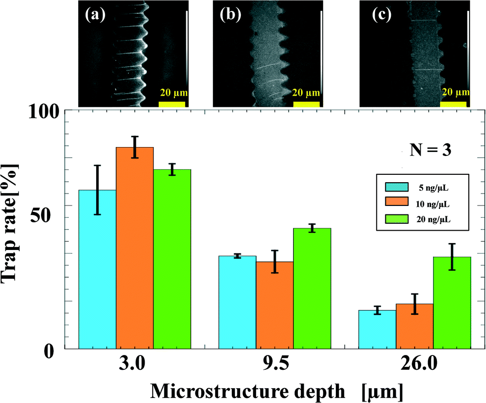 | ||
| Fig. 2 Rate of DNA trapping for different cavity depths in zigzag structures. | ||
Next, the trap rates for different zigzag pattern sizes and shapes were investigated. The first type of zigzag pattern was designed as a combination of line and equilateral triangles in a plane. The cavity designed as an equilateral triangle works as a guide to induce single DNA molecules to the edge of the groove. The drawings with different side lengths in Fig. 3 show the equilateral triangle patterns tested in our experiment. The side lengths of 15 μm and 10 μm showed high trap rates (84.4 ± 4.5% and 81.2 ± 3.4%, respectively); there was no significant difference between them. On the other hand, the trap rate significantly decreased (39.4 ± 7.3%) when the side length was 5 μm. In the second design of the zigzag pattern, the equilateral triangles were replaced by isosceles triangles. The shape of a narrow-angled isosceles triangle was expected to cause efficient induction of DNA molecules to the edge of the groove. The drawings with the different side lengths in Fig. 4 show the isosceles triangles tested in our experiment. The base of the isosceles triangles was fixed at 5 μm, and the legs were 5 μm, 7.5 μm, 10 μm, and 15 μm. Compared with the equilateral triangle pattern, the isosceles triangles, especially with legs measuring 10 μm and 15 μm, showed higher trap rates (77.0 ± 12.2% and 81.9 ± 10.8%, respectively). Under such conditions, over 1500 DNA molecules were successfully stretched and aligned simultaneously at each occurrence. The area value of the triangles was also used to analyze the efficiency of the DNA trapping at the zigzag vertices. As shown in Fig. 5, an exponential distribution of the trap rates was observed. For example, the trap rate of λDNA molecules reached a maximum value (84.4 ± 4.5% and 81.9 ± 10.8%) when the area value of the triangle was over 40 μm2. This indicates that the relationship between the adsorption possibility of DNA and the size of the cavity can be described as an exponential rise to the maximum. The number of grooves did not show any effect on the trapping efficiency.
 | ||
| Fig. 3 Rate of DNA trapping for different sizes of equilateral triangles used in cavity design in zigzag structures. | ||
 | ||
| Fig. 4 Rate of DNA trapping for different shapes of isosceles triangles used in cavity design in zigzag structures. | ||
 | ||
| Fig. 5 Relationship between adsorption possibility of DNA and the area of the triangle used in cavity design in zigzag structures. | ||
According to the relationship obtained by this research, a high density of aligned DNA molecules in a microfluidic molecular combing device can be achieved by constructing the microfabricated zigzag pattern in the shape of smaller isosceles triangles with a narrower vertex angle. Here, we studied the benefits and feasibility of the microfluidic molecular stretching device with different depths, sizes, and shapes of microfabricated zigzag patterns for DNA trapping at a single molecule level. Factors such as the rate of liquid flow for solution transportation and the width of the groove can also be optimized for the high-density DNA array. Moreover, the intervals between the grooves, which correspond to the space for the DNA molecules to be stretched, can be customized and designed for a specific DNA size. As can be seen from the micrographs in Fig. 1 and 2, the distance between the zigzag vertices (20 μm) was set relative to the maximal overstretching length of λDNA (48.5 kbp)15 (see Fig. S5‡). By using a customized setup, it would be possible to stretch longer DNA strands in this microfluidic molecular combing process, and shorter DNA fragments containing fewer than 1000 bp would also be trapped at the zigzag vertices. Moreover, the size of an unknown DNA sample is estimated from the length distribution of DNA observed at a single-molecule level. When measuring a DNA fragment from a very small blood sample, super resolution microscopy (see Fig. S6‡) would most likely resolve the size of the trapped DNA fragments in the microfluidic molecular stretching device. In this study, the minimum DNA concentration at which one can operate the device was 5 ng μL−1, but the lower DNA concentration could be applicable.
Conclusions
Parallel stretching and stamping of terminal-unmodified single DNA molecules in a PDMS microfluidic channel was demonstrated. In the course of drawing liquid with a syringe, the DNA molecules were trapped between the grooves in the microfluidic channel. The vertices of the grooves, which were designed as zigzag lines, successfully stretched the DNA molecules. A triangular cavity in the zigzag patterns induced single DNA molecules to the edge of the groove. The trapping efficiency of DNA at the zigzag vertices was highly influenced by the depth, shape, and size of the cavity. Simultaneous alignment of over 1500 DNA molecules was achieved by the microfluidic transfer of the liquid interface. Achieving a high density of aligned DNA molecules would be possible by using micro- or nanofabricated fine zigzag patterns on the surface.Acknowledgements
This research is supported by the Japan Society for the Promotion of Science through its “Funding Program for World-Leading Innovative R&D on Science and Technology”. This research is partly supported by the Japan Society for the Center of Innovation Program from Japan Science and Technology Agency, JST.We thank Dr. T. Naito of Kyoto University for his support with video monitoring of DNA stretching. We thank Dr. H. Hida of Kobe University and Dr. M. Horade of Osaka University for support with the fabrication of the device.
References
- R. K. Neely, J. Deen and J. Hofkens, Biopolymers, 2011, 95, 298–311 CrossRef CAS PubMed.
- S. Kim, et al. , Angew. Chem., Int. Ed., 2012, 51, 3578–3581 CrossRef CAS PubMed.
- Y. Michaeli, et al. , Chem. Commun., 2013, 49, 8599–8601 RSC.
- A. Cerf, B. R. Cipriany, J. J. Benitez and H. G. Craighead, Anal. Chem., 2011, 83, 8073–8077 CrossRef CAS PubMed.
- W. Cai, H. Aburatani, V. P. Stanton Jr, D. E. Housman, Y. K. Wang and D. C. Schwartz, Proc. Natl. Acad. Sci. U. S. A., 1995, 92, 5164–5168 CrossRef CAS.
- M. Shin, et al. , Nano Lett., 2006, 6, 1334–1338 CrossRef CAS PubMed.
- P. Bjork, S. Holmstrom and O. Inganas, Small, 2006, 2, 1068–1074 CrossRef PubMed.
- J. Gorman, et al. , Langmuir, 2009, 26, 1372–1379 CrossRef PubMed.
- B. Georgette, et al. , Nano Lett., 2008, 8, 1785–1790 CrossRef PubMed.
- T. Yasui, et al. , Anal. Chem., 2011, 83, 6635–6640 CrossRef CAS PubMed.
- E. C. Greene, S. Wind, T. Fazio, J. Gorman and M. L. Visnapuu, Methods Enzymol., 2010, 472, 293–315 CAS.
- R. Lebofsky and A. Bensimon, Briefings Funct. Genomics Proteomics, 2003, 1, 385–396 CrossRef CAS.
- X. Michalet, et al. , Science, 1997, 277, 1518–1523 CrossRef CAS.
- Z. Gueroui, C. Place, E. Freyssingeas and B. Berge, Proc. Natl. Acad. Sci. U. S. A., 2002, 99, 6005–6010 CrossRef CAS PubMed.
- C. A. P. Petit and J. D. Carbeck, Nano Lett., 2003, 3, 1141–1146 CrossRef CAS.
- A. Bensimon, et al. , Science, 1994, 265, 2096–2098 CAS.
- D. Bensimon, A. J. Simon, V. Croquette and A. Bensimon, Phys. Rev. Lett., 1995, 74, 4754–4757 CrossRef CAS.
- J.-F. Allemand, et al. , Biophys. J., 1997, 73, 2064–2070 CrossRef CAS.
- J. Hu, et al. , Langmuir, 1996, 12, 1697–1700 CrossRef CAS.
- A. T. Woolley and R. T. Kelly, Nano Lett., 2001, 1, 345–348 CrossRef CAS.
- J. Li, et al. , Nucleic Acids Res., 1998, 26, 4785–4786 CrossRef CAS PubMed.
- Z. Deng and C. Mao, Nano Lett., 2003, 3, 1545–1548 CrossRef CAS.
- J. H. Kim, W.-X. Shi and R. G. Larson, Langmuir, 2007, 23, 755–764 CrossRef CAS PubMed.
- H. Yokota, et al. , Anal. Chem., 1997, 71, 4418–4422 CrossRef.
- C. Aline, A. Thomas, R. A. Barton and H. G. Craighead, Nano Lett., 2011, 11, 4232–4238 CrossRef PubMed.
- F. Gentile, et al. , Nano Lett., 2012, 12, 6453–6458 CrossRef CAS PubMed.
- C. J. Lin, et al. , Biomicrofluidics, 2010, 4, 034103 CrossRef PubMed.
- B. Charlot, et al. , Biomicrofluidics, 2014, 8, 014103 CrossRef CAS PubMed.
- J. Guan and L. J. Lee, Proc. Natl. Acad. Sci. U. S. A., 2005, 102, 18321–18325 CrossRef CAS PubMed.
- S. K. Sia and G. M. Whitesides, Electrophoresis, 2003, 24, 3563–3576 CrossRef CAS PubMed.
- N. Kaji, Y. Okamoto, M. Tokeshi and Y. Baba, Chem. Soc. Rev., 2010, 39, 948–956 RSC.
Footnotes |
| † The authors declare no competing financial interests. |
| ‡ Electronic supplementary information (ESI) available. See DOI: 10.1039/c4lc00990h |
| § Both authors contributed equally to this work. |
| ¶ Authors' contributions statement: H. Y., D. O., T. Y., N. K., and Y. B. designed the research plan; D. O. performed the investigation research; H. Y. performed experiments; H. Y., D. O., T. Y., and N. K. analyzed data; and H. Y., D. O., T. Y., H. Y., N. K., and Y. B. wrote the paper. |
| This journal is © The Royal Society of Chemistry 2015 |