DOI:
10.1039/C4LC00798K
(Paper)
Lab Chip, 2015,
15, 121-134
Breakup dynamics and dripping-to-jetting transition in a Newtonian/shear-thinning multiphase microsystem
Received
9th July 2014
, Accepted 23rd September 2014
First published on 23rd September 2014
Abstract
The breakup dynamics in non-Newtonian multiphase microsystems is associated with a variety of industrial applications such as food production and biomedical engineering. In this study, we numerically and experimentally characterize the dripping-to-jetting transition under various flow conditions in a Newtonian/shear-thinning multiphase microsystem. Our work can help to predict the formation of undesirable satellite droplets, which is one of the challenges in dispensing non-Newtonian fluids. We also demonstrate the variations in breakup dynamics between shear-thinning and Newtonian fluids under the same flow conditions. For shear-thinning fluids, the droplet size increases when the capillary number is smaller than a critical value, while it decreases when the capillary number is beyond the critical value. The variations highlight the importance of rheological effects in flows with a non-Newtonian fluid. The viscosity of shear-thinning fluids significantly affects the control over the droplet size, therefore necessitating the manipulation of the shear rate through adjusting the flow rate and the dimensions of the nozzle. Consequently, the droplet size can be tuned in a controlled manner. Our findings can guide the design of novel microdevices for generating droplets of shear-thinning fluids with a predetermined droplet size. This enhances the ability to fabricate functional particles using an emulsion-templated approach. Moreover, elastic effects are also investigated experimentally using a model shear-thinning fluid that also exhibits elastic behaviors: droplets are increasingly deformed with increasing elasticity of the continuous phase. The overall understanding in the model multiphase microsystem will facilitate the use of a droplet-based approach for non-Newtonian multiphase applications ranging from energy to biomedical sciences.
1. Introduction
The microfluidic multiphase system can be applied in a wide variety of applications. For example, it can facilitate drug encapsulation and release using emulsion droplets as a template to fabricate core–shell microspheres, capsules and other functional materials.1–3 The system can also be used for the generation of jets, which can work as precursors of microfibers for application in wound dressing and tissue engineering.2,4–7 Nevertheless, the practical microfluidic multiphase applications increasingly demand the use of fluids with more complex rheological behaviors, such as non-Newtonian fluids, whose viscosities change with the applied stress. Non-Newtonian fluids are ubiquitous in daily life; examples include blood, lotions, creams, shampoos and toothpaste. They are also widely used in industrial applications such as inkjet printing, spraying and coating.8,9 Microscaled non-Newtonian multiphase systems have been increasingly applied in biomedical engineering, food production, and energy applications. For instance, an electrokinetic microdevice has been developed to convert fluidic mechanical energy to electrical energy by means of electrokinetic phenomena such as streaming currents.9 By reducing the hydrodynamic conductance while maintaining the same streaming current, addition of an appropriate polymer to the working fluid in a microchannel can enhance energy conversion efficiency, which is the ratio of electrical output power and hydrodynamic input power.10,11
The non-Newtonian multiphase microsystem has become a subject of intense research, and it is of paramount importance to understand the relevant physical phenomena, one of which involves the deformation of liquid threads and subsequently droplet formation. The performance of the droplets is intimately tied to the ability to control the droplet size, which has a strong impact on droplet stability as well as optical and mechanical properties.12 For example, when the droplets are used as a template to fabricate micro/nanoparticles for the drug delivery system, the shape and size of emulsion droplets have significant impacts on drug release kinetics.13,14 Monodisperse droplets with precisely controlled sizes can be used to deliver an accurate dosing of contained payload such as drug, flavoring, or chemical reactants.15 Therefore, monodispersity and size tenability are highly desired for ensuring that the droplets exhibit constant, controlled and predictable behaviors.4,12 However, the complex rheological properties of non-Newtonian fluids challenge the versatility in droplet size control. For example, the stretching and/or thinning of non-Newtonian liquid filaments will lead to the formation of “bead-on-string” patterns.16,17 These beads can subsequently become undesirable satellite droplets, increasing the polydispersity of the resultant droplet population. The dynamics of the droplet formation process can be characterized into a dripping and a jetting regime. The dripping-to-jetting transition can be estimated using the capillary number of the continuous phase, Caout, the ratio of viscous force to surface tension, and the Weber number of the dispersed phase, Wein, the ratio of inertial force to surface tension.18
| |  | (1) |
| |  | (2) |
where
ρDP is the density of dispersed phase,
d refers to the diameter of the orifice,
VDP and
VCP are the velocities of dispersed and continuous phase, respectively,
σ is the interfacial tension, and
ηCP,0 is the apparent viscosity of the non-Newtonian fluid of the continuous phase. The subscript “0” refers to zero-shear rate when a shear-dependent fluid is used. Droplet formation occurs at the orifice directly after the two fluids meet in the dripping process, when both Ca
out and We
in are small, as surface tension dominates. In contrast, jetting occurs when Ca
out or We
in is large, as the viscous stress or the inertial force on the droplet will be large enough to overcome surface tension. Droplets are generated after the breakup of a jet at some distance downstream in this regime. While the dynamics of the droplet breakup has been systematically investigated in Newtonian fluids,
17,18 the validity of the understanding has not been adequately confirmed in non-Newtonian fluid systems. In addition, a number of non-Newtonian fluids such as polymeric solutions, whole blood or protein solutions with large polymeric molecules often exhibit elastic properties due to the stretching and coiling of the polymer chains. The resultant non-Newtonian rheological behaviors inspire interesting applications.
19 For instance, microparticles driven in viscoelastic solutions can migrate toward the centerline of a microchannel because of the first normal stress difference between the centerline and the walls; three-dimensional (3D) particle focusing can be achieved
via a combination of inertial and elastic forces.
20 The elasticity of the focusing fluid has been shown to facilitate formation of smaller droplets.
21 These examples attest to the need for a comprehensive understanding of the role of elastic fluids with shear-rate-dependent viscosity in droplet formation using microfluidic systems.
In this paper, we focus on a shear-thinning fluid, which is one of the most frequently encountered non-Newtonian fluids,22 and investigate the dripping-to-jetting transition of a Newtonian/shear-thinning two-phase system and characterize the formation of satellite drops in the model system. The breakup time and droplet size are compared with a Newtonian/Newtonian two-phase system at the same Weber number and capillary number. We demonstrate that the degree of control over the droplet size can be enhanced by adjusting the flow rate and nozzle size, thus tuning the shear rate experienced by the non-Newtonian fluids. We also present an experimental study of the elasticity effect of a shear-thinning fluid on droplet generation in a microfluidic two-phase system. The shape of the droplets is shown to vary with the Weissenberg number, which is the ratio of the relaxation time to the hydrodynamic time. Our work helps to elucidate the effects of rheological behaviors on the breakup dynamics in a Newtonian/non-Newtonian two-phase microscale flow; our understanding inspires new approaches to control sizes and shapes of functional droplets in applications requiring the use of non-Newtonian fluids.
2. Numerical model
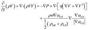
The microcapillary co-flow device has been widely used in emulsion generation.23 A 3D numerical model with the same design is established in the present investigation (see Fig. 1a). A Newtonian fluid as the dispersed phase is injected into a cylindrical capillary at a constant average velocity VDP. This inner fluid is surrounded by a non-Newtonian outer phase as the continuous phase, which is injected through the coaxial square capillary at a constant average velocity VCP. The cross section (perpendicular to the main flow direction) consists of a circle inside a square (see the inset of Fig. 1a). Thus, the continuous phase is flowing through a cross section between an inner circle and an outer square. The no-slip condition is applied at the solid boundaries of the walls of capillaries. A gauge pressure of zero is applied at the outlet of the domain. The maximum entrance length is 9.4 μm in our numerical computations, and the length of the computational domain is 6 mm, which is long enough to ensure that the fluid flow can fully develop. The governing equations for incompressible two-phase fluids are24| |  | (3) |
| |  | (4) |
| |  | (5) |
| | | ρ = αCPρCP + (1 − αCP)ρDP | (6) |
| | | η = αCPηCP + (1 − αCP)ηDP | (7) |
where V is the flow velocity, P is the pressure, ρ is the volume-averaged density, αCP and ρCP are the volume fraction and density of the continuous phase, respectively, and ηDP and ηCP are the dynamic viscosities of dispersed and continuous phases, respectively. The 3D numerical volume of fluid (VOF) model has been implemented to investigate the droplet breakup in a pair of non-Newtonian/Newtonian fluids in a T-shaped microchannel.24 The rheological properties of the non-Newtonian continuous phase are modeled using the Cross model, which has been widely applied in the modeling of industrial shear-thinning fluids.25 A shear-thinning fluid is used in our present study and its apparent viscosity is defined by| |  | (8) |
where η∞ refers to lower limiting values of the fluid viscosity or infinite shear viscosity; η0 refers to upper limiting values of the fluid viscosity or zero shear viscosity; λC is the time constant, the reciprocal of which corresponds to a critical shear rate that provides a useful indicator of the onset shear rate for shear thinning; ![[small gamma, Greek, dot above]](https://www.rsc.org/images/entities/i_char_e0a2.gif) is the shear rate in 3D flows and is defined as the magnitude of the rate of the deformation tensor:
is the shear rate in 3D flows and is defined as the magnitude of the rate of the deformation tensor:  , where D is the rate of deformation; and n represents the power law index of fluid. The solutions with different values of these parameters will have different rheological behaviors. Any effect due to gravity is neglected for simplicity because the length scale of interest is much smaller than the capillary length of 1.33 mm in our model. The two-phase flow is solved using the VOF method by CFD software Ansys Fluent 14.0. The approach has been successfully demonstrated to investigate multiphase flow in a microsystem.26 The governing equations are discretized to algebraic equations by using a control-volume-based technique. An iterative solver was deployed to solve the control-volume discretized equations. The iterative time step is 10−7 s and the solution converges when the residual is below 1.0 × 10⁻⁶. The simulations were performed using numerical grids composed of triangular elements, as shown in Fig. 1b. The numerical data was subsequently analyzed by Ansys CFX-Post 14.0 after the simulation was completed. Computational sensitivity studies have been carried out to evaluate the effect of different triangular grid sizes. The generated morphology of the interface as indicated by the green color between dispersed and continuous phases is compared using different grid sizes. Similar morphology is found at flow rates of the dispersed phase QDP = 50 ml h−1, and of the continuous phase QCP = 70 ml h−1, as shown in Fig. 2. The size of the interface gradually increases along the axial direction, and subsequently adopts a cylindrical shape downstream with a uniform size for grid sizes of 4 μm and 8 μm. The variation in the generated size of the interface is less than 5% after convergence between grid sizes of 4 μm and 8 μm. Furthermore, we investigated the grid size effect by comparing numerical results of the axial velocity profile along the transverse direction (x direction) for different grid sizes, at two downstream locations, z = 0.02 mm, where the two phases meet in the vicinity of the orifice, and z = 5.27 mm, where the flow has become fully developed, as shown in Fig. 3a and b, respectively. At z = 0.02 mm, the sharp peak in the middle represents the velocity profile of the dispersed phase, which is purged out of the orifice with a very small size; thus the velocity will increase dramatically due to mass conservation. The magnitude of the velocity for the continuous phase is much smaller because of the much larger cross section. At z = 5.27 mm, the velocity profiles of dispersed and continuous phases adjoin with a smooth transition at the interface. Compared with coarse grids with a size of 12 μm, good agreement is found between refined grids with a size of 4 μm and 8 μm. 4
![[thin space (1/6-em)]](https://www.rsc.org/images/entities/char_2009.gif) 300
300![[thin space (1/6-em)]](https://www.rsc.org/images/entities/char_2009.gif) 956 triangular elements with a size of 8 μm are used in all of the following numerical simulations to reduce computational cost.
956 triangular elements with a size of 8 μm are used in all of the following numerical simulations to reduce computational cost.
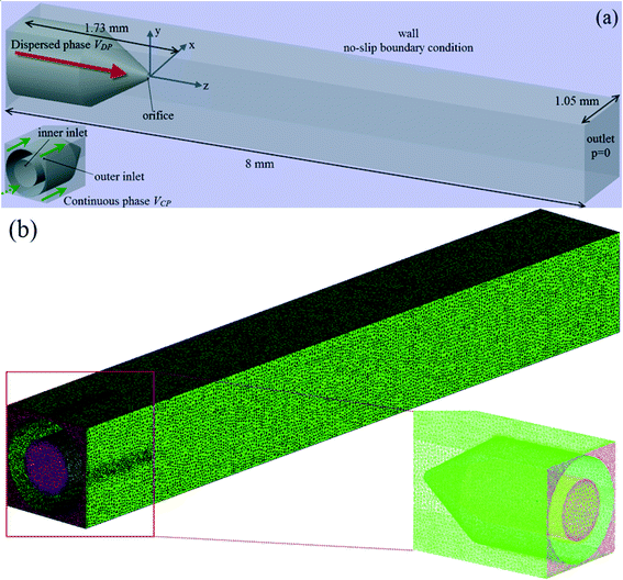 |
| | Fig. 1 (a) Schematic of the computational domain of the multiphase microfluidic system. (b) Meshing grids. The close-up view of meshing of the nozzle and inlets is shown in the inset. | |
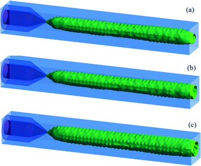 |
| | Fig. 2 Comparison of morphology of jet using different meshing grid sizes: (a) 0.012 mm (b) 0.008 mm and (c) 0.004 mm. QDP = 50 ml h−1, QCP = 70 ml h−1. | |
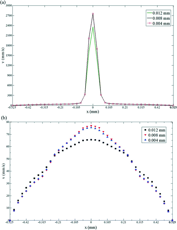 |
| | Fig. 3 Validation of the numerical model of Newtonian/shear-thinning multiphase microfluidic system by comparison of axial velocity profile along the transverse direction (x direction) at (a) z = 0.02 mm and (b) z = 5.27 mm using different meshing grid sizes. | |
3. Experimental section
The Newtonian/shear-thinning two-phase co-flow is generated using a glass microcapillary device reported earlier.23 A glass slide was used as a substrate to support the capillary device, which is composed of an inner round capillary (World Precision Instruments, Inc.) and an outer square capillary (Atlantic International Technology, Inc.). The round capillary has inner and outer diameters of 630 μm and 1.0 mm, respectively, and its tip was tapered to the desired diameter by a micropipette puller (Sutter Instrument, Inc.) to obtain an orifice with an inner diameter of about 49 μm. The tapered round capillary was fitted into the square capillary, which has an inner diameter of 1.05 mm. Since the outer diameter of the round capillary matches with the inner diameter of the square capillary, coaxial alignment of the two capillaries is ensured. The dispersed phase was injected into the device through the circular capillary, while the continuous phase was injected in the same direction through the square capillary. The fluids were injected into the device through flexible plastic tubing (Scientific Commodities Inc.), which was connected to syringe pumps (Longerpump, LSP01-2A) at controlled flow rates. Unless otherwise specified, the chemicals used in the study were supplied by Aladdin Reagents (Shanghai) Co., Ltd. In the present study, the dispersed phase was silicone oil, while the continuous phase was 2% (w/v) aqueous solution of sodium carboxymethyl cellulose (CMC) (Mw = 250![[thin space (1/6-em)]](https://www.rsc.org/images/entities/char_2009.gif) 000 Da, DS = 1.2), which is a pseudo-plastic fluid and demonstrates shear-thinning behaviors. The rheological behavior of CMC solution can be characterized by two critical concentrations:27 a first critical CMC concentration indicates the transition to the semidilute network solution, while a second critical CMC concentration indicates the transition to the concentrated solution. Below the second critical concentration, the CMC solution becomes highly viscous and the dynamics is dominated by viscous effects; above the second critical concentration, the dynamics become dominated by elastic effects. For CMC solution with a nominal molecular weight of 700
000 Da, DS = 1.2), which is a pseudo-plastic fluid and demonstrates shear-thinning behaviors. The rheological behavior of CMC solution can be characterized by two critical concentrations:27 a first critical CMC concentration indicates the transition to the semidilute network solution, while a second critical CMC concentration indicates the transition to the concentrated solution. Below the second critical concentration, the CMC solution becomes highly viscous and the dynamics is dominated by viscous effects; above the second critical concentration, the dynamics become dominated by elastic effects. For CMC solution with a nominal molecular weight of 700![[thin space (1/6-em)]](https://www.rsc.org/images/entities/char_2009.gif) 000 Da and a degree of substitution of 0.65–0.85, the first critical concentration is ~1% while its second critical concentration is 2.5%.27 The effect of concentration and molecular weight on the rheological behavior of aqueous CMC solutions has been investigated experimentally.28 Based on their measurements of the rheological properties, solutions of CMC with molecular weights of 90
000 Da and a degree of substitution of 0.65–0.85, the first critical concentration is ~1% while its second critical concentration is 2.5%.27 The effect of concentration and molecular weight on the rheological behavior of aqueous CMC solutions has been investigated experimentally.28 Based on their measurements of the rheological properties, solutions of CMC with molecular weights of 90![[thin space (1/6-em)]](https://www.rsc.org/images/entities/char_2009.gif) 000 Da, 250
000 Da, 250![[thin space (1/6-em)]](https://www.rsc.org/images/entities/char_2009.gif) 000 Da, and 700
000 Da, and 700![[thin space (1/6-em)]](https://www.rsc.org/images/entities/char_2009.gif) 000 Da all exhibit predominantly shear-thinning behaviors over a shear rate of 0–1000 s−1 in the absence of yield stress as their concentration changes from 0.1% to 3.0%. In our work, the average shear rate of CMC solution is below 1000 s−1 by controlling the flow rate. Therefore, it is reasonable to assume that our CMC solution (Mw = 250
000 Da all exhibit predominantly shear-thinning behaviors over a shear rate of 0–1000 s−1 in the absence of yield stress as their concentration changes from 0.1% to 3.0%. In our work, the average shear rate of CMC solution is below 1000 s−1 by controlling the flow rate. Therefore, it is reasonable to assume that our CMC solution (Mw = 250![[thin space (1/6-em)]](https://www.rsc.org/images/entities/char_2009.gif) 000 Da, DS = 1.2) still has a predominantly viscous behavior, and the elastic effect can be ignored.28
000 Da, DS = 1.2) still has a predominantly viscous behavior, and the elastic effect can be ignored.28
We also prepared 5% (w/v) aqueous solution of polyacrylamide (PAA, supplied by Wing Hing Chemical Co., Ltd) as the continuous phase to investigate the elastic effect on breakup dynamics and droplet formation. The flow behavior inside the microcapillary device was monitored with an inverted microscope (Motic, ocular: WF10 × 18 mm, object lens: EA4). A high-speed camera (Phantom version 9.1 high speed camera) was connected to the microscope, and the flow through the capillary was captured. The dripping-to-jetting transition using non-Newtonian systems was characterized experimentally, and the breakup dynamics in a non-Newtonian fluid system was compared with that in a Newtonian fluid system at the same Weber number and capillary number using the same microdevice. For the Newtonian two-phase flow, silicone oil was also used as the dispersed phase, while 17% w/v aqueous solution of polyethylene glycol (PEG) (Mw = 8000 Da) was used as the continuous phase. The interfacial tension was measured by a Kruss SITE100 spinning drop tensiometer. The respective viscosity of each solution was measured at different shear rates using a Brookfield DV-II+Pro programmable viscometer. Shear-thinning behavior of the CMC solution was observed experimentally. The rheology data of CMC solution at all concentrations can be well represented by the well-known Cross model;27 therefore, the Cross model was used in curve fitting of the experimental data, and the measured Cross model parameters (the zero shear viscosity η0 = 253.5 cP, infinite shear viscosity η∞ = 60 cP, and the flow index n = 0.9, as shown in Fig. 4) were used in the simulation for computing the simulation results, which were subsequently compared with the experimental observations. As a comparison, we also use the Carreau model in curve fitting of the experimental data of the CMC solution. The agreement with the experiment value is not as good as that with the Cross model. The fitting quality of the two models was evaluated by the corresponding standard deviation and Pearson correlation coefficient,29 which are 0.329 and 0.934, respectively, for the Carreau model, and 0.095 and 0.980, respectively, for the Cross model. The smaller standard deviation and larger Pearson correlation coefficient suggest that the rheological behavior of CMC solution is better modelled using the Cross model; thus the Cross model is chosen over the Carreau model. Very small variations of viscosity were observed at different shear rates (see Fig. 4), indicating that 17% (w/v) PEG solution exhibits largely Newtonian properties. The concentration of PEG solution can affect the rheological properties. For example, 7% (w/w) PEG solution shows significantly different viscosity values at different shear rates, demonstrating a non-Newtonian behavior.30 5% (w/v) PAA solution possesses shear-thinning behavior, as shown in Fig. 4. As a typical viscoelastic liquid, the rheological properties of PAA have been well investigated, and the storage modulus G′ and loss modulus G′′ have been measured using an oscillatory shear rheometer.31 Based on the reported data, we find the relaxation time λ to be 0.017 s, according to the Maxwell model of viscoelastic liquid.32 Relevant dimensionless numbers of viscoelastic liquids include the Weissenberg number Wi and elasticity number El. The Weissenberg number is defined as the product of the relaxation time and a characteristic rate of deformation of the flow, and quantifies the nonlinear response of the liquid.
| |  | (9) |
where
U is the average axial flow velocity in the capillary device and
Dt refers to the dimensions of the capillary tube. Wi is dependent on the flow rate and varies in the range between 0.0041 and 0.041 in our experiments. The ratio between elastic and inertial effects is represented by the elasticity number
| |  | (10) |
where Re refers to Reynolds number. El is thus independent of the flow rate based on the definition. In our experiments El = 382, indicating the dominating role of elastic effect relative to inertia effect. The physical properties of the fluids used in the investigation are shown in
Table 1.
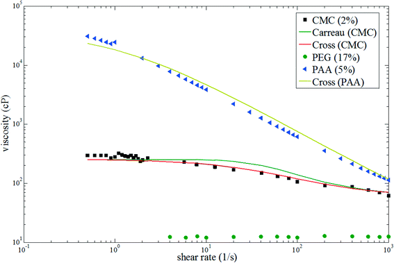 |
| | Fig. 4 Rheological properties of the three aqueous polymer solutions: 2% w/v sodium carboxymethyl cellulose (CMC) in water (black squares), 17% w/v polyethylene glycol (PEG) in water (green circles), 5% w/v polyacrylamide (PAA) in water (blue triangles), Cross model of CMC solution (red solid line), Carreau model of CMC solution (green solid line) and Cross model of PAA solution (yellow solid line). | |
Table 1 Physical properties of the test fluids
| Test fluids |
η (cP) |
ρ (g ml−1) |
σ (mN m−1) (silicone oil and CMC) |
σ (mN m−1) (silicone oil and PEG) |
σ (mN m−1) (silicone oil and PAA) |
| Silicone oil |
10 |
0.963 |
7.12 |
9.624 |
10.176 |
| CMC (2%) |
253.5 (zero-shear rate) |
0.990 |
| PEG (17%) |
13.6 |
1.053 |
| PAA (5%) |
24![[thin space (1/6-em)]](https://www.rsc.org/images/entities/char_2009.gif) 569 (zero-shear rate) 569 (zero-shear rate) |
0.992 |
4. Results and discussion
The breakup dynamics and dripping-to-jetting transition in Newtonian/shear-thinning multiphase microsystem are presented and discussed first, followed by a discussion of elastic effect on the droplet shape at the end of this section. Simulation and experiments of Newtonian/shear-thinning multiphase flow in the capillary microdevice have been conducted under the same flow conditions to observe the process of jet deformation and droplet formation. Silicone oil and CMC solution are used as the dispersed phase and the continuous phase, respectively. The flow pattern at successive time points from the simulation is shown in Fig. 5. The flow rates of the dispersed and continuous phases are 5 and 7 ml h−1, respectively, with Caout = 0.0631 and Wein = 5.147. The transition regime is observed and the jet size changes along the length of the jet. The dispersed phase is purged out of the orifice, as shown by the inset in Fig. 5a. The droplet grows in size and moves downstream while it is still connected to the fluid neck through the orifice via a filament, as shown in Fig. 5b. The filament gradually becomes thinner (see Fig. 5c) and finally breaks up into a droplet (see Fig. 5d). The process is repeated afterwards. The interface between the two phases in Fig. 5d is tracked by plotting the radius of the interface along the transverse direction (y direction) versus the streamwise location along the z direction. The simulation result is represented by the solid line and is compared with experimental measurements indicated by the symbols. Reasonable agreement, as shown in Fig. 5e, validates the accuracy of the numerical model.
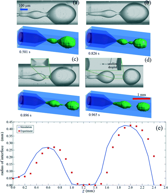 |
| | Fig. 5 Time-lapse images of jet deformation and droplet formation from simulation (upper one in each sub-figure) and experiments (lower one in each sub-figure) using a Newtonian/shear-thinning two-phase co-flow system (silicone oil as dispersed phase and CMC solution as continuous phase). The blue and red scale bars are the experimental and simulation results, respectively. (a) The dispersed phase is purged out of the orifice; (b) the main droplet is connected to the fluid neck via a thin filament; (c) the filament becomes even much thinner; (d) satellite droplet occurs after the breakup of the jet; (e) tracking of interface profile by both simulation and experimental observation. | |
A satellite droplet is formed during the breakup of an elongated filament between two adjacent droplets. The profile near the breakup point is highly asymmetric, with the droplet interface being very steep towards the droplet while lying flat towards the neck of the jet. The existence of satellite drops is intimately related to the non-linear properties of fluid motion close to the breakup point.33 When the filament breaks at both ends before merging with one of the parent droplets, the filament separates from both neighboring parent droplets and recoils into a satellite droplet.34 The number of satellite droplets and their relative sizes strongly depend on the ratio of the viscosity of the dispersed phase to that of the continuous phase and are also influenced by the initial disturbance wavenumber, which is defined as 2πa/ε, where a is the radius of the filament and ε is the wavelength.35 At a small viscosity ratio, the slender center droplet undulates and pinches off at a number of locations, generating a string of small satellite droplets. In contrast, when the viscosity ratio is large, the internal flow leading to the breakup is attenuated, resulting in the formation of fewer satellite droplets. As the wavenumber increases, the ratio of the radius of satellite droplets in different birth regions relative to the radius of the parent droplet also increases.35
Since the satellite droplets have a much smaller size than the main droplet, the global polydispersity of the resultant emulsion increases. To predict the occurrence of satellite droplets, the flow conditions that result in the formation of satellite droplets have been delineated using a state diagram, which shows the two-phase flow pattern as a function of Weber number and capillary number. Three representative flow regimes are observed when the flow rate ratio is varied, as shown in Fig. 6a: dripping, where droplets are formed in the vicinity of the capillary tip; intermediate, where the growing droplets move downstream while remaining connected to the fluid in the tip through a fluid neck;18 and jetting, where droplets breaks up from an extended jet with an incomplete retraction of the fluid neck. For the intermediate regime, the fluid neck retracts completely back to the tip after the droplet pinches off at the detachment point of the fluid neck. This regime is thus still regarded as dripping.18 Upon further increase of viscous or inertial force, for instance, by changing the flow rate of the continuous or the dispersed phase, the intermediate regime will transition to the jetting regime. Comparison of results from simulation and experiments shows good agreement, confirming the validity of our model in capturing the physical behavior of the two-phase flow when a non-Newtonian fluid is used. As Wein increases, the viscosity of the shear-thinning continuous phase decreases when subjected to a high shear rate. As a result, a lower viscous stress is exerted on the dispersed phase; the liquid thread is therefore not pulled further downstream. Consequently, the flow remains in the intermediate regime rather than in the jetting regime. However, when Wein is larger than 10, jetting occurs because of the larger inertial force. Based on experimental observation, satellite droplets appear only in the intermediate regime, which is characterized as a dripping-to-jetting transition,18 as shown in the state diagram in Fig. 6b. Inertia is necessary to induce the formation of a satellite droplet, because droplet formation will be suppressed when the viscous force is dominant over inertia. However, a very large inertial force will lead to formation of jetting and the liquid thread will break up into droplets further downstream. Consequently, the pinch-off time increases, delaying the formation of the parent droplet and satellite droplets. This state diagram can help predict the formation of undesirable satellite droplets in a Newtonian/shear-thinning two-phase system and can suggest operating conditions for eliminating satellite droplets. This ultimately inspires production of monodisperse droplets by manipulating the breakup profile and controlling the merging of satellite droplets with main droplets; yet these investigations are beyond the scope of the present study.
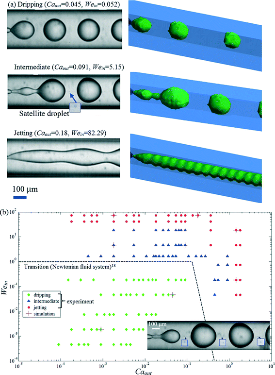 |
| | Fig. 6 (a) Comparison of results from simulation and experiments at different regimes using a Newtonian/shear-thinning two-phase coflow system (silicone oil as dispersed phase and CMC solution as continuous phase). (b) State diagram showing the dripping-jetting transition as a function of Caout and Wein. The inset shows the satellite droplets appearing periodically between adjacent parent droplets. The dash line (reprinted (Fig. 4) with permission from ref. 18 as follows: Utada et al., Phys. Rev. Lett., 2007, 99, 094502. Copyright (2014) by the American Physical Society) shows the dripping-to-jetting transition in a purely Newtonian two-phase coflow system (deionized water and polydimethylsiloxane (PDMS) oil). | |
The breakup time is one of the determining factors in the droplet production rate. It is thus of fundamental interest and industrial relevance to investigate the breakup time when non-Newtonian fluids, for example, shear-thinning fluids, are used, in comparison to their counterpart in the Newtonian multiphase system at the same Wein and Caout. A droplet breakup occurs due to the interplay between the viscous stress and the interfacial tension between the two fluids. The viscous stress is closely associated with the shear rate, which varies greatly depending on the position. The shear rate affects the viscosity in all directions in the 3D flow. The highly deformed filament connecting the fluid neck to the droplet (see Fig. 5b) is of particular interest because it is the region where the breakup occurs. We will therefore use the filament region, for instance, z = 0.87 mm, as the focal point to characterize the shear-rate-dependent viscosity profile. Given the continuity of the velocity at the interface and the small diameter of the filament, the shear rate reaches a sharp peak at the interface between the two phases in the filament region. Due to shear-thinning characteristics of the CMC solution, the viscosity will be dramatically reduced at the interface, as shown by the numerically calculated results of the viscosity and shear rate as a function of radial location along the transverse direction of the capillary device in Fig. 7. The magnitude of the shear rate of the continuous phase in the co-flowing microfluidic device with a dimension of Dt is related to the droplet diameter Dd through26
| |  | (11) |
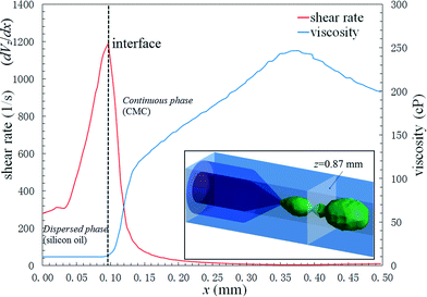 |
| | Fig. 7 Numerically calculated viscosity and shear rate as a function of radial position along the transverse direction of the capillary device of the Newtonian/shear-thinning two-phase co-flow system (silicone oil as dispersed phase and CMC solution as continuous phase) at z = 0.87 mm, which is illustrated in the inset. | |
The expression suggests that a droplet of fixed size will be subjected to a larger shear rate when the flow rate increases, and that a droplet of larger size will induce a higher shear rate at a fixed flow rate, because the larger droplet will tend to disrupt and confine the flow of the continuous phase, unless the dimensions of the microcapillary tube can be changed. Given the flow conditions in Fig. 5, where QCP = 7 mL h−1 and  ,
, ![[small gamma, Greek, dot above]](https://www.rsc.org/images/entities/i_char_e0a2.gif) ~1.65 s−1. The calculated shear rate of the continuous phase is of the same order of magnitude as the simulation result of shear rate, which refers to the derivative of the axial flow velocity with respect to the radial coordinate, dVz/dx, in Fig. 7. A local maximum shear rate of 9.68 s−1 for the continuous phase is obtained at the wall of the collection tube because of the no-slip condition at the wall and the large velocity gradient in the boundary layer adjacent to the wall. The shear rate is reduced in the region far from the wall, and a minimum value of 3.87 s−1 is obtained at r = 0.375 mm.
~1.65 s−1. The calculated shear rate of the continuous phase is of the same order of magnitude as the simulation result of shear rate, which refers to the derivative of the axial flow velocity with respect to the radial coordinate, dVz/dx, in Fig. 7. A local maximum shear rate of 9.68 s−1 for the continuous phase is obtained at the wall of the collection tube because of the no-slip condition at the wall and the large velocity gradient in the boundary layer adjacent to the wall. The shear rate is reduced in the region far from the wall, and a minimum value of 3.87 s−1 is obtained at r = 0.375 mm.
For shear thinning fluids, the viscosity is inversely proportional to the shear rate; thus the viscous effect will be attenuated near regions with high shear rate, facilitating the pinch off of the jet. Consequently, the breakup process will speed up so that a higher production rate of droplets can be expected. To verify the hypothesis that a shorter breakup time can be achieved when a shear thinning fluid is involved, control tests have been conducted to monitor the breakup time for the purely Newtonian two-phase system. The dimensionless pinching time, ![[t with combining circumflex]](https://www.rsc.org/images/entities/i_char_0074_0302.gif) p = tp/tv = tp/(η0d/σ), was measured experimentally at the same Wein and Caout, where tp and tv refer to the measured time interval between two successive pinching and the viscous timescale, respectively. When compared with the Newtonian system with constant viscosity, the shear-thinning fluid near the liquid–liquid interface has a much reduced viscosity due to a high shear rate; as a result, at the same capillary number, surface force dominates and the pinching is faster when a shear-thinning fluid is used as the continuous phase. The dimensionless breakup time is also reduced when Caout increases due to the enhanced viscous shear stress exerted on the droplets, as shown in Fig. 8, where Wein = 1.852.
p = tp/tv = tp/(η0d/σ), was measured experimentally at the same Wein and Caout, where tp and tv refer to the measured time interval between two successive pinching and the viscous timescale, respectively. When compared with the Newtonian system with constant viscosity, the shear-thinning fluid near the liquid–liquid interface has a much reduced viscosity due to a high shear rate; as a result, at the same capillary number, surface force dominates and the pinching is faster when a shear-thinning fluid is used as the continuous phase. The dimensionless breakup time is also reduced when Caout increases due to the enhanced viscous shear stress exerted on the droplets, as shown in Fig. 8, where Wein = 1.852.
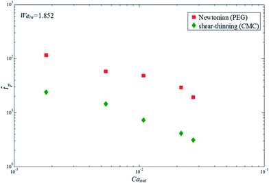 |
| | Fig. 8 Comparison of the experimentally observed breakup time of jet into droplets using the Newtonian/shear-thinning two-phase co-flow system (silicone oil as dispersed phase and CMC solution as continuous phase) versus Newtonian/Newtonian two-phase co-flow system (silicone oil as dispersed phase and PEG solution as continuous phase) when Wein = 1.852. | |
In the breakup process of the liquid jet of the dispersed phase, the droplets are formed and surrounded by the continuous phase. The droplet size is influenced by the viscous force and the surface tension force. Due to the reduced viscosity of the continuous phase, the droplet size is larger when a shear-thinning fluid is used at the same Wein and Caout.36 This is confirmed by the observed snapshots of droplets after the breakup at the same Weber number but at different capillary numbers in two different multiphase systems, as shown in Fig. 9. In both cases, silicone oil is used as the dispersed phase, while solutions of PEG and CMC are used as the Newtonian and non-Newtonian continuous phases, respectively. At the same Weber number of 1.852, both systems show a decrease in the droplet size when the capillary number is increased from 0.0018 to 0.054 (see Fig. 10) due to the higher shear stress and the enhanced hydrodynamic focusing effect by the continuous phase.
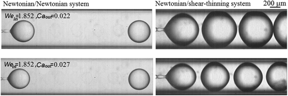 |
| | Fig. 9 Comparison of droplet size between Newtonian/shear-thinning two-phase coflow system (silicone oil as dispersed phase and CMC solution as continuous phase) and Newtonian/Newtonian multiphase coflow system (silicone oil as dispersed phase and PEG solution as continuous phase). | |
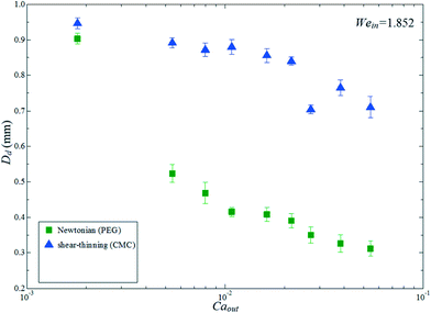 |
| | Fig. 10 Comparison of the experimentally observed droplet diameter between the Newtonian/shear-thinning two-phase system (silicone oil as dispersed phase and CMC solution as continuous phase) and the Newtonian/Newtonian two-phase system (silicone oil as dispersed phase and PEG solution as continuous phase).Wein = 1.852 in all cases. | |
Control of the droplet size is also an important aspect of droplet-based microfluidic applications. For example, the volume of the droplet which contains reagents or analytes is one of the key parameters that determine the efficiency and the overall throughput of the system.37 Since non-Newtonian fluids are ubiquitous in biochemical applications of microfluidics, it is also crucial to control the droplet size. To achieve smaller droplets, we vary the dimensions of the nozzles by fitting a round capillary with radius R into the square capillary (see Fig. 11). At a constant flow rate of the outer phase and a constant capillary number, evaluated based on the apparent viscosity, the shear rate increases with decreasing inner diameter of the collection capillary, leading to an increase in shear stress and thus reduced droplet sizes, as shown by the observed droplets in the collection tube with two different sizes in Fig. 11. The droplet size is significantly reduced when a collection tube with a smaller radius of 0.3 mm is used (see the sub-figures on the right) as compared to that with a radius of 0.5 mm (see the sub-figures on the left) at the same Weber number and capillary number.
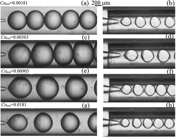 |
| | Fig. 11 Observed droplets in collection tubes with different sizes (R = 0.5 mm in a, c, e and g; R = 0.3 mm in b, d, f and h) using a Newtonian/shear-thinning two-phase system (silicone oil as dispersed phase and CMC solution as continuous phase). Caout = 0.00181 in a–b, Caout = 0.00363 in c–d, Caout = 0.00903 in e–f, and Caout = 0.0181 in g–h. Wein = 0.206 in all cases. | |
As Caout and the shear rate of the continuous phase increase, the viscosity of the continuous phase is reduced for shear-thinning fluids such as CMC; this results in larger droplets.36 However, when Caout increases beyond a critical value, the viscous drag can overcome the surface tension effects that would otherwise minimize the stretching of the fluid neck by drawing the fluid interfaces closer to the orifice. As a result, the fluid neck becomes stretched and elongated at high Caout.
When a round capillary with radius R is inserted into the square capillary, we consider the shear rate of the continuous phase that flows by the fluid neck of the dispersed phase with radius rj; Dt can be replaced with 2R, and Dd can be replaced with 2rj in eqn (11). Therefore, the shear rate is defined by
| |  | (12) |
The thinning of the fluid neck occurs when it is stretched and elongated at high Caout. Thus, as the radius of the fluid neck decreases, the shear rate of the continuous phase (i.e., CMC in our case) starts to decrease, and the viscosity of the continuous phase will increase for a shear-thinning fluid. As a result, the droplet size will start to reduce beyond a critical Caout, as shown in Fig. 12 when Wein = 0.206. When the inner radius of the collection tube is 0.3 mm, the droplet size increases from 0.40 mm to 0.55 mm as Caout is increased from 1.5 × 10⁻⁴ to 0.0053, while the droplet size is reduced to 0.38 mm when Caout is further increased to 0.015. At a given Weber number, the droplet size first increases below a certain critical capillary number due to the reduced viscosity and then decreases above the critical capillary number when the viscosity starts to increase again. The correlation between the droplet size and the capillary number in the Newtonian/shear-thinning two-phase system is different from that in the Newtonian/Newtonian two-phase system, which normally shows that droplet size scales inversely with the capillary number of the continuous phase in a monotonous fashion.38 The different correlation highlights the complex viscosity effect towards the control over emulsion droplets generated with fluid–fluid systems involving shear-thinning non-Newtonian fluids. This understanding can provide information needed for designing microdevices for generating droplets with well-defined volumes when shear-thinning non-Newtonian multiphase systems are involved. For example, given certain flow conditions and fluid properties (thus, Wein and Caout are known), an analysis can be done to determine the size of the collection tube of the microdevice according to the expected size of droplets in demand.
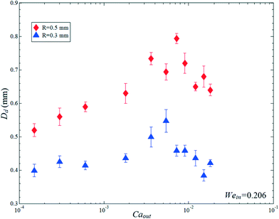 |
| | Fig. 12 Experimental results of droplet size as a function of capillary number for a given collection tube in a Newtonian/shear-thinning two-phase system (silicone oil as dispersed phase and CMC solution as continuous phase). Wein = 0.206. | |
When a Newtonian liquid is surrounded by a shear-thinning liquid with pronounced elastic properties, the droplet breakup dynamics are modified. We observe flow patterns at different ratios of flow rate of 5% (w/v) PAA solution, which is the viscoelastic continuous phase, to that of silicone oil as the dispersed phase, as shown in Fig. 13. The flow rate of the dispersed phase is fixed at 1 ml h−1 in Fig. 13a–f, and 10 ml h−1 in Fig. 13g–i. The elastic forces from the viscoelastic continuous phase can help to overcome interfacial tension and thus facilitate transition to jetting at smaller magnitudes of the viscous forces. Compared to the aforementioned Newtonian/Newtonian or Newtonian/shear-thinning multiphase microsystem where droplets normally adopt a spherical or nearly spherical shape, the droplets experience significant deformation in the viscoelastic non-Newtonian continuous phase. For instance, the droplets adopt an elliptical shape after the breakup and relax into pointed shapes. Droplets become more pointed as the radius decreases and the flow rate ratio increases before they transition to the jetting regime (see Fig. 13a–f). The degree of droplet deformation has been characterized based on Taylor's analysis39
| |  | (13) |
where
L is the half-length and
W the half-breadth of the droplet.
Df increases with increasing Weissenberg number (thus more pronounced elastic effect), leading to formation of droplets with a more pointed shape, as shown in
Fig. 14. This observation is consistent with the previous finding that elasticity of the suspending liquid can facilitate the deformation of Newtonian droplets.
40 Our work provides a platform which will help to facilitate understanding of the complex rheological behavior of viscoelastic fluid and how this behavior can affect breakup dynamics and droplet formation in a multiphase microfluidic system.
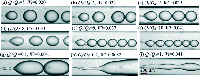 |
| | Fig. 13 Flow patterns at selected flow rate ratios of continuous phase over dispersed phase in a Newtonian/elastic-shear-thinning two-phase system (silicone oil as dispersed phase and PAA solution as continuous phase). Qd = 1 ml h−1 for (a)–(f), and Qd = 10 ml h−1 for (g)–(i). | |
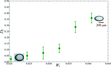 |
| | Fig. 14 Degree of deformation of droplet as a function of Weissenberg number in a Newtonian/elastic-shear-thinning two-phase system (silicone oil as dispersed phase and PAA solution as continuous phase). The inset images show that the droplet adopts a nearly spherical shape at low Wi, and a pointed shape at high Wi, respectively. The scale bar applies for both inset images. | |
5. Conclusions
The study reports emulsion formation using a Newtonian/shear-thinning two-phase microsystem. With a shear-thinning continuous phase, the droplet dynamics is characterized to predict the dripping-to-jetting transitions under different flow conditions (as a function of Weber number and capillary number), where undesirable satellite droplets may form. Inertial effects have been shown to be important for inducing the formation of a satellite droplet, while droplet formation can be suppressed by increasing the viscous effect. Due to the shear-thinning characteristics of the continuous phase used in the present study, the viscosity is dramatically reduced at the interface; the viscous effect is therefore attenuated, leading to a faster breakup and a larger droplet size. Emulsions generated with non-Newtonian fluids are routinely involved in drug delivery and other biochemical applications. Accurate dosing must be ensured for reliable operation, and this requires excellent control over the droplet size. We also identify the correlation between the droplet size and the capillary number, potentially enabling a higher degree of control over the size of the emulsion droplets generated with shear-thinning fluids. Finally, a viscoelastic fluid is used as the continuous non-Newtonian phase, and the degree of Newtonian droplet deformation increases with increasing Weissenberg number of suspending non-Newtonian fluid, indicating the important impact of elasticity on the droplet shape. Our work provides a first framework for understanding a range of behaviors in non-Newtonian multiphase microsystems, although we recognize the vast variety of non-Newtonian fluids besides the two types (shear-thinning solution with or without elastic properties) we have investigated and the large regions of unexplored operating conditions. For example, it is challenging to generate droplets with non-Newtonian fluids in aqueous two-phase systems (ATPS) due to much lower interfacial tension when compared with oil–water systems.41,42 Furthermore, it is also of great interest to investigate the cases when non-Newtonian fluid is used as the dispersed phase rather than just the continuous phase. Improvement in polydispersity of the resultant droplets can also be achieved potentially by developing and implementing methods to dynamically control the merging of satellite droplets with the main droplets. This approach of elimination of satellite droplets will also lead to droplets with higher size uniformity in applications that inevitably involve non-Newtonian multiphase flows.
Acknowledgements
This research was supported by the Early Career Scheme (HKU 707712P) and the General Research Fund (HKU 719813E) from the Research Grants Council of Hong Kong, the Young Scholar's Program (NSFC51206138/E0605) from the National Natural Science Foundation of China, the Basic Research Program-General Program (JC201105190878A) from the Science and Technology Innovation Commission of Shenzhen Municipality, as well as the Seed Funding Programme for Basic Research (201211159090) and the Small Project Funding (201109176165) from the University of Hong Kong.
References
- H. C. Shum, D. Lee, I. Yoon, T. Kodger and D. A. Weitz, Langmuir, 2008, 24, 7651–7653 CrossRef CAS PubMed.
- T. Kong, J. Wu, M. To, K. W. K. Yeung and H. C. Shum, Biomicrofluidics, 2012, 6, 034104 Search PubMed.
- C. I. Zoldesi, P. Steegstra and A. Imhof, J. Colloid Interface Sci., 2007, 308, 121–129 CrossRef CAS PubMed.
- J. K. Nunes, S. S. H. Tsai, J. Wan and H. A. Stone, J. Phys. D: Appl. Phys., 2013, 46, 114002 CrossRef PubMed.
- C. H. Choi, H. Yi, S. Hwang, D. A. Weitz and C. Lee, Lab Chip, 2011, 11, 1477 RSC.
- C. M. Hwang, A. Khademhosseini, Y. Park, K. Sun and S. Lee, Langmuir, 2008, 24, 6845–6851 CrossRef CAS PubMed.
- J. Wu, T. Kong, K. W. K. Yeung, H. C. Shum, K. M. C. Cheung, L. Wang and M. K. T. To, Acta Biomater., 2013, 9(7), 7410–7419 CrossRef CAS PubMed.
- Ö. E. Yıldırım and O. A. Basaran, J. Non-Newtonian Fluid Mech., 2006, 136, 17–37 CrossRef PubMed.
- A. R. Abate, M. Kutsovsky, S. Seiffert, M. Windbergs, L. F. V. Pinto, A. Rotem, A. S. Utada and D. A. Weitz, Adv. Mater., 2011, 23, 1757–1760 CrossRef CAS PubMed.
- C. L. A. Berli, J. Colloid Interface Sci., 2010, 349, 446–448 CrossRef CAS PubMed.
-
T. Nguyen, Y. Xie, L. J. de Vreede, A. van den Berg and J. C. T. Eijkel, 16th Int. Conf. on Miniaturized Systems for Chemistry and Life Sciences, 2012, pp. 1987–1989 Search PubMed.
- D. J. Mcclements, Crit. Rev. Food Sci. Nutr., 2007, 47, 611–649 CrossRef CAS PubMed.
- A. Budhian, S. J. Siegel and K. I. Winey, Int. J. Pharm., 2007, 336, 367–375 CrossRef CAS PubMed.
- C. Berkland, M. King, A. Cox, K. Kim and D. Pack, J. Controlled Release, 2002, 82, 137–147 CrossRef CAS.
- R. M. Erb, D. Obrist, P. W. Chen, J. Studer and A. R. Studart, Soft Matter, 2011, 7, 8757 RSC.
- M. S. N. Oliveira and G. H. McKinley, Phys. Fluids, 2005, 17, 071704 CrossRef PubMed.
- J. Eggers and E. Villermaux, Rep. Prog. Phys., 2008, 71, 036601 CrossRef.
- A. S. Utada, A. Fernandez-Nieves, H. A. Stone and D. A. Weitz, Phys. Rev. Lett., 2007, 99, 094502 CrossRef.
-
R. G. Larson, The structure and rheology of complex fluids, Oxford University Press, Oxford, 1999 Search PubMed.
- S. Yang, J. Y. Kim, S. J. Lee, S. S. Lee and J. M. Kim, Lab Chip, 2011, 11, 266 RSC.
- L. Derzsi, M. Kasprzyk, J. P. Plog and P. Garstecki, Phys. Fluids, 2013, 25, 092001 Search PubMed.
- G. Pangalos, J. M. Dealy and M. B. Lyne, J. Rheol., 1985, 29, 471–491 CrossRef CAS.
- A. Sauret, C. Spandagos and H. C. Shum, Lab Chip, 2012, 12, 3380 RSC.
- L. Sang, Y. Hong and F. Wang, Microfluid. Nanofluid., 2009, 6, 621–635 CrossRef CAS.
-
C. L. Tucker, Fundamentals of computer modeling for polymer processing, Hanser Publishers, New York, 1989 Search PubMed.
- Y. Hong and F. Wang, Microfluid. Nanofluid., 2007, 3, 341–346 CrossRef CAS.
- A. Benchabane and K. Bekkour, Colloid Polym. Sci., 2008, 286(10), 1173–1180 CAS.
-
K. Benyounes, 13th SGEM GeoConference on Science and Technologies In Geology, Exploration and Mining, 2013, pp. 951–995 Search PubMed.
- S. M. F. D. Syed Mustapha, T. N. Phillips, C. J. Price, L. G. Moseley and T. E. R. Jones, Eng. Appl. Artif. Intel., 1999, 12, 255 CrossRef.
- S. D. Geschiere, I. Ziemecka, V. van Steijn, G. J. M. Koper, J. H. van Esch and M. T. Kreutzer, Biomicrofluidics, 2012, 6, 022007 CrossRef PubMed.
-
A. Kreiba, The Rheological Properties of Aqueous Polyacrylamide Solutions, Concordia University, 2000 Search PubMed.
-
R. G. Larson, Constitutive Equation for Polymer Melts and Solutions, Butterworth-Heinemann, 1988 Search PubMed.
- J. Eggers, Z. Angew. Math. Mech., 2005, 85, 400–410 CrossRef.
- M. Rohani, F. Jabbari and D. Dunn-Rankin, Phys. Fluids, 2010, 22, 107103 CrossRef PubMed.
- M. Tjahjadi, H. A. Stone and J. M. Ottino, J. Fluid Mech., 1992, 243, 297–317 CrossRef CAS.
- G. I. Taylor, Proc. R. Soc. London, Ser. A, 1932, 138, 41–47 CrossRef CAS.
- H. Song, D. L. Chen and R. F. Ismagilov, Angew. Chem., Int. Ed., 2006, 45, 7336–7356 CrossRef CAS PubMed.
- C. A. Stan, S. K. Y. Tang and G. M. Whitesides, Anal. Chem., 2009, 81, 2399–2402 CrossRef CAS PubMed.
- G. I. Taylor, Proc. R. Soc. London, Ser. A, 1934, 501, 146 Search PubMed.
- D. C. Tretheway and L. G. Leal, J. Non-Newtonian Fluid Mech., 2001, 99, 81–108 CrossRef CAS.
- Y. Song, A. Sauret and H. C. Shum, Biomicrofluidics, 2013, 7, 061301 CrossRef PubMed.
- A. Sauret and H. C. Shum, Appl. Phys. Lett., 2013, 100, 154106 Search PubMed.
Footnote |
| † Current Address: Department of Mechanical, Materials & Manufacturing Engineering, The University of Nottingham, Ningbo, China. |
|
| This journal is © The Royal Society of Chemistry 2015 |
Click here to see how this site uses Cookies. View our privacy policy here. 


![[small gamma, Greek, dot above]](https://www.rsc.org/images/entities/i_char_e0a2.gif) is the shear rate in 3D flows and is defined as the magnitude of the rate of the deformation tensor:
is the shear rate in 3D flows and is defined as the magnitude of the rate of the deformation tensor:  , where D is the rate of deformation; and n represents the power law index of fluid. The solutions with different values of these parameters will have different rheological behaviors. Any effect due to gravity is neglected for simplicity because the length scale of interest is much smaller than the capillary length of 1.33 mm in our model. The two-phase flow is solved using the VOF method by CFD software Ansys Fluent 14.0. The approach has been successfully demonstrated to investigate multiphase flow in a microsystem.26 The governing equations are discretized to algebraic equations by using a control-volume-based technique. An iterative solver was deployed to solve the control-volume discretized equations. The iterative time step is 10−7 s and the solution converges when the residual is below 1.0 × 10⁻⁶. The simulations were performed using numerical grids composed of triangular elements, as shown in Fig. 1b. The numerical data was subsequently analyzed by Ansys CFX-Post 14.0 after the simulation was completed. Computational sensitivity studies have been carried out to evaluate the effect of different triangular grid sizes. The generated morphology of the interface as indicated by the green color between dispersed and continuous phases is compared using different grid sizes. Similar morphology is found at flow rates of the dispersed phase QDP = 50 ml h−1, and of the continuous phase QCP = 70 ml h−1, as shown in Fig. 2. The size of the interface gradually increases along the axial direction, and subsequently adopts a cylindrical shape downstream with a uniform size for grid sizes of 4 μm and 8 μm. The variation in the generated size of the interface is less than 5% after convergence between grid sizes of 4 μm and 8 μm. Furthermore, we investigated the grid size effect by comparing numerical results of the axial velocity profile along the transverse direction (x direction) for different grid sizes, at two downstream locations, z = 0.02 mm, where the two phases meet in the vicinity of the orifice, and z = 5.27 mm, where the flow has become fully developed, as shown in Fig. 3a and b, respectively. At z = 0.02 mm, the sharp peak in the middle represents the velocity profile of the dispersed phase, which is purged out of the orifice with a very small size; thus the velocity will increase dramatically due to mass conservation. The magnitude of the velocity for the continuous phase is much smaller because of the much larger cross section. At z = 5.27 mm, the velocity profiles of dispersed and continuous phases adjoin with a smooth transition at the interface. Compared with coarse grids with a size of 12 μm, good agreement is found between refined grids with a size of 4 μm and 8 μm. 4
![[thin space (1/6-em)]](https://www.rsc.org/images/entities/char_2009.gif) 300
300![[thin space (1/6-em)]](https://www.rsc.org/images/entities/char_2009.gif) 956 triangular elements with a size of 8 μm are used in all of the following numerical simulations to reduce computational cost.
956 triangular elements with a size of 8 μm are used in all of the following numerical simulations to reduce computational cost.


![[thin space (1/6-em)]](https://www.rsc.org/images/entities/char_2009.gif) 000 Da, DS = 1.2), which is a pseudo-plastic fluid and demonstrates shear-thinning behaviors. The rheological behavior of CMC solution can be characterized by two critical concentrations:27 a first critical CMC concentration indicates the transition to the semidilute network solution, while a second critical CMC concentration indicates the transition to the concentrated solution. Below the second critical concentration, the CMC solution becomes highly viscous and the dynamics is dominated by viscous effects; above the second critical concentration, the dynamics become dominated by elastic effects. For CMC solution with a nominal molecular weight of 700
000 Da, DS = 1.2), which is a pseudo-plastic fluid and demonstrates shear-thinning behaviors. The rheological behavior of CMC solution can be characterized by two critical concentrations:27 a first critical CMC concentration indicates the transition to the semidilute network solution, while a second critical CMC concentration indicates the transition to the concentrated solution. Below the second critical concentration, the CMC solution becomes highly viscous and the dynamics is dominated by viscous effects; above the second critical concentration, the dynamics become dominated by elastic effects. For CMC solution with a nominal molecular weight of 700![[thin space (1/6-em)]](https://www.rsc.org/images/entities/char_2009.gif) 000 Da and a degree of substitution of 0.65–0.85, the first critical concentration is ~1% while its second critical concentration is 2.5%.27 The effect of concentration and molecular weight on the rheological behavior of aqueous CMC solutions has been investigated experimentally.28 Based on their measurements of the rheological properties, solutions of CMC with molecular weights of 90
000 Da and a degree of substitution of 0.65–0.85, the first critical concentration is ~1% while its second critical concentration is 2.5%.27 The effect of concentration and molecular weight on the rheological behavior of aqueous CMC solutions has been investigated experimentally.28 Based on their measurements of the rheological properties, solutions of CMC with molecular weights of 90![[thin space (1/6-em)]](https://www.rsc.org/images/entities/char_2009.gif) 000 Da, 250
000 Da, 250![[thin space (1/6-em)]](https://www.rsc.org/images/entities/char_2009.gif) 000 Da, and 700
000 Da, and 700![[thin space (1/6-em)]](https://www.rsc.org/images/entities/char_2009.gif) 000 Da all exhibit predominantly shear-thinning behaviors over a shear rate of 0–1000 s−1 in the absence of yield stress as their concentration changes from 0.1% to 3.0%. In our work, the average shear rate of CMC solution is below 1000 s−1 by controlling the flow rate. Therefore, it is reasonable to assume that our CMC solution (Mw = 250
000 Da all exhibit predominantly shear-thinning behaviors over a shear rate of 0–1000 s−1 in the absence of yield stress as their concentration changes from 0.1% to 3.0%. In our work, the average shear rate of CMC solution is below 1000 s−1 by controlling the flow rate. Therefore, it is reasonable to assume that our CMC solution (Mw = 250![[thin space (1/6-em)]](https://www.rsc.org/images/entities/char_2009.gif) 000 Da, DS = 1.2) still has a predominantly viscous behavior, and the elastic effect can be ignored.28
000 Da, DS = 1.2) still has a predominantly viscous behavior, and the elastic effect can be ignored.28


![[thin space (1/6-em)]](https://www.rsc.org/images/entities/char_2009.gif) 569 (zero-shear rate)
569 (zero-shear rate)

 ,
, ![[small gamma, Greek, dot above]](https://www.rsc.org/images/entities/i_char_e0a2.gif) ~1.65 s−1. The calculated shear rate of the continuous phase is of the same order of magnitude as the simulation result of shear rate, which refers to the derivative of the axial flow velocity with respect to the radial coordinate, dVz/dx, in Fig. 7. A local maximum shear rate of 9.68 s−1 for the continuous phase is obtained at the wall of the collection tube because of the no-slip condition at the wall and the large velocity gradient in the boundary layer adjacent to the wall. The shear rate is reduced in the region far from the wall, and a minimum value of 3.87 s−1 is obtained at r = 0.375 mm.
~1.65 s−1. The calculated shear rate of the continuous phase is of the same order of magnitude as the simulation result of shear rate, which refers to the derivative of the axial flow velocity with respect to the radial coordinate, dVz/dx, in Fig. 7. A local maximum shear rate of 9.68 s−1 for the continuous phase is obtained at the wall of the collection tube because of the no-slip condition at the wall and the large velocity gradient in the boundary layer adjacent to the wall. The shear rate is reduced in the region far from the wall, and a minimum value of 3.87 s−1 is obtained at r = 0.375 mm.![[t with combining circumflex]](https://www.rsc.org/images/entities/i_char_0074_0302.gif) p = tp/tv = tp/(η0d/σ), was measured experimentally at the same Wein and Caout, where tp and tv refer to the measured time interval between two successive pinching and the viscous timescale, respectively. When compared with the Newtonian system with constant viscosity, the shear-thinning fluid near the liquid–liquid interface has a much reduced viscosity due to a high shear rate; as a result, at the same capillary number, surface force dominates and the pinching is faster when a shear-thinning fluid is used as the continuous phase. The dimensionless breakup time is also reduced when Caout increases due to the enhanced viscous shear stress exerted on the droplets, as shown in Fig. 8, where Wein = 1.852.
p = tp/tv = tp/(η0d/σ), was measured experimentally at the same Wein and Caout, where tp and tv refer to the measured time interval between two successive pinching and the viscous timescale, respectively. When compared with the Newtonian system with constant viscosity, the shear-thinning fluid near the liquid–liquid interface has a much reduced viscosity due to a high shear rate; as a result, at the same capillary number, surface force dominates and the pinching is faster when a shear-thinning fluid is used as the continuous phase. The dimensionless breakup time is also reduced when Caout increases due to the enhanced viscous shear stress exerted on the droplets, as shown in Fig. 8, where Wein = 1.852.


