An experimental study on the numbering-up of microchannels for liquid mixing
Yuanhai
Su
ab,
Guangwen
Chen
b and
Eugeny Y.
Kenig
*ac
aChair of Fluid Process Engineering, Faculty of Mechanical Engineering, University of Paderborn, D-33098, Paderborn, Germany. E-mail: eugeny.kenig@upb.de; Fax: +49 5251 60 2183; Tel: +49 5251 60 2408
bDalian National Laboratory for Clean Energy, Dalian Institute of Chemical Physics, Chinese Academy of Sciences, Dalian, 116023, China
cGubkin Russian State University of Oil and Gas, Moscow, Russian Federation
First published on 22nd October 2014
Abstract
The numbering-up of zigzag-form microchannels for liquid mixing was experimentally investigated in a multichannel micromixer including 8 parallel channels, based on the Villermaux–Dushman reaction system, with an appropriate sulphuric acid concentration. The results showed that the micromixing performance in such micromixers could reach the same quality as in a single microchannel, when flat constructal distributors with bifurcation configurations were used. The mixing performance did not depend on whether a vertical or horizontal micromixer position was selected. Surprisingly, the channel blockage somewhat increased the micromixing performance in the multichannel micromixer due to the fluid redistribution effect of the constructal distributors. This effect could also be confirmed by CFD simulations. However, the channel blockage resulted in a higher pressure drop and thus higher specific energy dissipation in the multichannel micromixer. The local pressure drop caused by fluid splitting and re-combination in the numbering-up technique could be neglected at low Reynolds numbers, but it became larger with increasing flow rates. The operational zone for the mixing process in multichannel micromixers was sub-divided into two parts according to the specific energy dissipation and the mixing mechanisms.
Introduction
Mixing represents an important phenomenon in many liquid processes, e.g., precipitation, crystallisation, polymerisation, self-catalysis, enzymatic catalysis, and many others, in which mixing and chemical reactions interact.1–7 Mixing on the molecular scale is usually called micromixing8 and plays a crucial role in the reaction processes, when the characteristic timescale of the chemical reactions involved is of the same magnitude or smaller than the timescale of the mixing process.9 In this case, the conversion and selectivity of chemical reactions largely depend on micromixing efficiency. In order to improve the overall process performance and product quality, it is necessary to design reactors with high micromixing efficiency.The development of microreactor/micromixer technology is remarkable in the area of process intensification technologies because of its obvious advantages, such as continuous operational mode, high mixing performance, enhanced heat and mass transfer, improved reaction selectivity and excellent process safety.10–14 A wide range of microreactors/micromixers have been designed and applied for liquid mixing and reaction processes on the laboratory scale. T-shaped or Y-shaped microchannels,15,16 interdigital micromixers,17 split-and-recombine micromixers,18 packed-bed micromixers,19 and multifunctional micromixers20 are representative examples with high mixing performance. Reduced diffusion distance, increased interfacial area and implemented flow disturbances are the main design specifics of these micromixers.21–24 From a practical point of view, T-shaped microchannel mixers are easy to design and manufacture, and thus they are widely used for laboratory tasks and have a high potential for industrial application.
In order to experimentally investigate the mixing performance in a micromixer, optical methods, such as microlaser-induced fluorescence (μ-LIF) detection, can be applied.25–28 This can be accomplished by introducing an inlet stream with a fluorescent dye and another inlet stream without a fluorescent dye into the microchannel.29 The fluorescence intensity field of the dye excited by the light beam is recorded with a camera and further transformed into the concentration field; afterwards, the mixing performance in the microchannel can be described. Hoffmann et al.25 utilized μ-LIF and micro-particle image velocimetry (μ-PIV) to characterize the mixing performance in a T-shaped micromixer. It was found that the flow was in the stratified regime and the feed streams flowed side by side at low Reynolds numbers, while the radial diffusion was weak. At higher Reynolds numbers, the flow changed to the engulfment regime from the stratified flow regime. The intertwining of both inlet streams in the T-junction resulted in an enlarged interfacial contact area and a steep concentration gradient and, hence, an improved mixing performance. It was further demonstrated that the diffusive mixing in microchannels could be controlled by a variation in the velocity profile. μ-LIF detection is mainly limited by the microchannel material, the detection limit of optimal equipment and the choice of dyes. Furthermore, optical methods usually can provide the information about the mixing performance on the macro- and mesoscale only.
In contrast to the optical method, the chemical probe method can easily detect the mixing performance on the molecular scale (micromixing). In this method, parallel or consecutive competing reaction systems are used to study the micromixing performance in stirred tanks or in continuous-flow mixers. One frequently applied parallel competing reaction scheme for characterising the micromixing in micromixers is the Villermaux–Dushman reaction system.17,19,30–38 For instance, Li et al.31 controlled the mesomixing scale of three different types of micromixers and characterised their micromixing performance. Their results provided an understanding of how the mesomixing scale affected the micromixing performance, which was helpful for the design and optimisation of micromixers. Kamio et al.38 developed a double-tubular counter-flow micromixer consisting of two stainless steel tubes (inner and outer) with different diameters as an asymmetric inlet structure. The inner tube was inserted into the outer tube at the T-junction of the micromixer, and one reactant fluid flowed in the mixing zone from the inner tube while the other flowed from the outer tube. The excellent micromixing performance was confirmed by the results of Villermaux–Dushman reactions. Su et al.19 investigated the hydrodynamics and micromixing efficiency in packed-bed microchannels by both high-speed imaging techniques and the Villermaux–Dushman method. Kölbl and Kraut33 demonstrated that different compositions of the resulting mixtures were achieved by feeding the acid stream through different inlets when using the Villermaux–Dushman reaction system to evaluate the mixing performance in T-junction and V-type micromixers. This means that the micromixing time could not be derived from the test chemical reactions based on simple mixing models without taking the specific geometry of the device into account.
It is well known that the numbering-up strategy is a common method to increase the throughput of microchannels. However, only few studies on the numbering-up of microchannels for liquid mixing processes have been reported up to now. Kölbl et al.37 designed and fabricated microchannel systems for multilamination mixers by stacking and bonding microstructured foils and examined the mixing performance in these so-called V-type micromixers by using the Villermaux–Dushman reaction method. The results showed that the throughput of V-type micromixers could be multiplied by varying the number of micromachined foils and keeping constant velocities of the fluids through the parallel microchannels while maintaining constant mixing quality. Furthermore, it was indicated that the arrangement of the microchannels at the interface between the microchannel system and the mixing chamber had a crucial impact on the mixing performance. Guo et al.39 fabricated a mini-mixer with 16 channels and a channel diameter of 1 mm or 2 mm and tested its mixing performance based on the Villermaux–Dushman reaction system in terms of segregation index, micromixing time and energy dissipation rate. Two feed fluids were distributed among 16 channels through distributors, then brought into contact at T-mixers, and finally collected in a collector. Both distributors and collector were designed following the arborescent shape. As the flow rate increased, the flow disturbance was enhanced, thus intensifying the micromixing performance. The authors claimed that the mixing performance obtained with a millimetric mixer was comparable to the performance of micromixers, and the design of the multichannel mixer with arborescent distributor and collector made the numbering-up of multiple channels possible. In general, however, the understanding of the influencing factors for the numbering-up of microchannels for liquid mixing processes is still insufficient.
Recently, we carried out computational fluid dynamic (CFD) simulations to investigate the liquid mixing in microchannels and the corresponding numbering-up process.40 It was found that the decrease in size of the lateral inlet and the zigzag form of the channels could improve the mixing performance in microchannels. The distance between the elbow and the closest split point was a key factor that influenced the performance of flat constructal distributors with bifurcation configurations, and the rounding of the elbow could significantly reduce the pressure drop in these distributors. The mixing performance in the multichannel micromixers with optimized microchannels and distributors was proven to be close to that of a single microchannel. However, it was difficult to simulate the whole multichannel micromixer because of the limitations of computer memory and simulation time, and the effects of connectors, collecting chamber and outlet on the numbering-up process were neglected. Obviously, more detailed investigations are necessary in order to establish an integral strategy for the numbering-up of microchannels for liquid mixing.
In this work, we utilized the Villermaux–Dushman reaction system with appropriate reactant concentrations to investigate the decisive factors affecting the micromixing performance in the numbering-up of single microchannels for liquid mixing. The micromixing performance in microchannels was evaluated by measuring the light absorption (Abs) of effluent at the microchannel outlets. The mixing performance in a single microchannel and in multichannel micromixers was compared in the numbering-up process. The effect of the micromixer position and random channel blockage on the mixing performance in the multichannel micromixers was studied. Furthermore, the pressure drop characteristics and the relationship between the specific energy dissipation and the micromixing performance in multichannel micromixers were examined.
Experimental section
Villermaux–Dushman reaction system
The Villermaux–Dushman reaction system includes the acid-catalyzed reaction of potassium iodide with potassium iodate to elemental iodine, competing with the fast neutralisation of the acid by a borate buffer system:30| H2BO3− + H+ → H3BO3 (quasi-instantaneous) | (R1) |
| 5I− + IO3− + 6H+ → 3I2 + 3H2O (fast) | (R2) |
| I2 + I− ↔ I3− (instantaneous) | (R3) |
The neutralisation reaction (R1) is quasi-instantaneous, while the redox reaction (R2) is fast but much slower than reaction (R1). The redox reaction (R2) is also called Dushman reaction. Reaction (R3) is an instantaneous equilibrium reaction. Under perfect micromixing conditions, the injected acid is instantaneously dispersed in the reaction medium and consumed by borates according to reaction (R1). Otherwise, the injected acid is consumed competitively by reactions (R1) and (R2), and the formed I2 can further react with I− to yield the triiodide complex (I3−) according to reaction (R3). The amount of I3− produced depends on micromixing efficiency and can be easily measured using a spectrophotometer at 353 nm. The farther micromixing is from ideality, the more I3− is formed and the stronger light absorption is detected. Therefore, the mixing process can be evaluated directly by the light absorption of the effluent from the outlet of the micromixer. Other mixing parameters, such as segregation index, micromixing time and micromixedness ratio, can further be derived from light absorption.
Experimental procedure
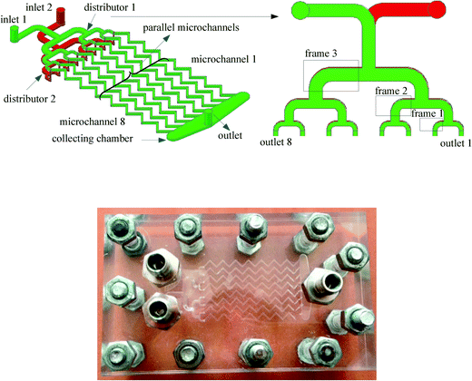
The schematic representation and a photo of a multichannel micromixer studied in this work are shown in Fig. 1. This multichannel micromixer was constructed in the transparent PMMA substrate by the micromachining technology. It mainly consisted of two inlets, two flat constructal distributors with bifurcation configurations, eight parallel zigzag-form microchannels, a collecting chamber and an outlet. A distributor for the first liquid was fabricated on one side of the plate. Parallel zigzag-form microchannels and a collecting chamber were fabricated on the same side of this plate. The collecting chamber was used to collect the reaction mixture from the parallel microchannels. Another distributor for the second fluid was fabricated on the other side of the plate, while its outlets were connected to the parallel microchannels. The plate was clamped tightly by another two plates with the help of bolts. Both the depth and the width of these parallel microchannels were 500 μm. Each microchannel had 14 zigzag-form structures with an overall length of 53 mm.The distributors comprised three generations. In the first generation, the inlet channel was split perpendicularly into two opposing channels, and then these two channels were further split in the second generation. This fabrication process for bifurcation formation finally resulted in 23 = 8 outlets for each distributor. The resulting channels in distributors have rounding corners. The numbering-up process of single microchannels could be realized within the same multichannel micromixer. This was done by selectively blocking the channels with sealing grease, thus resulting in different multichannel micromixers with 2, 4 and 8 channels. For example, in order to investigate the mixing performance in a single microchannel (channel 1), the elbows in both distributors 1 and 2 highlighted by the three frames in Fig. 1 and the ends of microchannels 2–8 were blocked with sealing grease. The sealing grease was resistant to aqueous solutions and showed no corrosion effect on the PMMA material. Blockages of the elbows in frames 2 and 3 and the ends of microchannels 3–8 resulted in the multichannel micromixer with 2 channels. With this blocking strategy, it is easy to obtain micromixers with different numbers of parallel channels. Furthermore, this method can be used to study the effect of random channel blockage on the mixing process in the multichannel micromixer. Moreover, the sealing grease in microchannels was easy to remove through washing with hexane without corroding the microchannels.
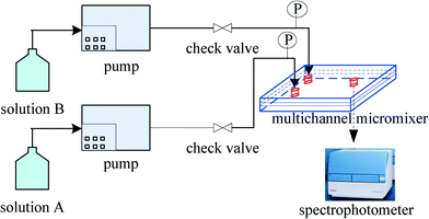
The schematic diagram of the experimental setup is shown in Fig. 2. Aqueous solutions A and B were fed into the micromixer at the same volumetric flow rate by two high-precision piston pumps. Solution A was a dilute sulphuric acid solution. Solution B was another aqueous solution containing potassium iodate (0.003 mol L−1), potassium iodide (0.016 mol L−1), sodium hydroxide (0.045 mol L−1), and boric acid (0.045 mol L−1). After collecting enough effluent from the micromixer using a sample cell (ca. 3 ml), light absorption was measured using a spectrophotometer. The pressure drop in the micromixer was measured with pressure transducers. Each experimental run was repeated at least three times, and each data point represented the mean value of at least three measurements of light absorption. The relative deviation did not exceed 5% in all experiments.
Results and discussion
Adjustment of the H2SO4 concentration
The light absorption of the resulting mixture in the Villermaux–Dushman reaction system strongly depends on H2SO4 concentration.34,35 A necessary condition is that the amount in moles of H+ in solution A is lower than the amount in moles of H2BO3+ in solution B in the mixing process, according to the stoichiometry of the Villermaux–Dushman reaction system. Otherwise, the redox reaction would occur and lead to the generation of triiodide complex even when the mixing process is perfect. Kölbl et al.34 pointed out that the rate of the Dushman reaction could be adjusted by choosing appropriate reactant concentrations in order to reach the maximum sensitivity. They carried out the mixing investigations in microstructured mixers with different H2SO4 concentrations and considered 0.015 mol l−1 as an optimum concentration.Different H2SO4 concentrations of 0.03, 0.015, 0.01 and 0.0075 mol l−1 were applied in the experiments with a single microchannel. Fig. 3 shows the effect of Reynolds number on the light absorption of the effluent of the single microchannel at different H2SO4 concentrations. It can be seen that light absorption reached the measuring limitation of the spectrophotometer in the studied range of Reynolds number for the H2SO4 concentration of 0.03 mol l−1. This was attributed to the excess protons that took part in the Dushman reaction during the mixing process. For the H2SO4 concentration of 0.015 mol l−1, light absorption has different values in the Reynolds number range of 200–1200, whereas for low Reynolds numbers in the range of 8–200, these values remained constant. This means that the sensitivity in the Reynolds number range of 8–200 is rather low. For the lowest H2SO4 concentration (0.0075 mol l−1), the light absorption at the Reynolds number of 200 was close to that at the Reynolds number of 400. We can conclude that this H2SO4 concentration does not permit discrimination of the mixing mechanisms in the Reynolds number range of 200–400. Engler et al.41 identified three different laminar flow regimes inside microchannels depending on the Reynolds number, namely, stratified flow (Re < 80), vortex flow (80 < Re < 240) and engulfment flow (240 < Re < 400). Furthermore, in most practical applications of micromixers and microreactors, Reynolds number does not exceed 400. Consequently, solution A with the H2SO4 concentration of 0.01 mol l−1 was chosen for the following study, because relatively high sensitivity could be obtained in the Reynolds number range of 0–400.
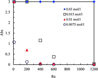 | ||
| Fig. 3 Effect of Reynolds number on the light absorption of the effluent of the single microchannel at different H2SO4 concentrations in solution A. | ||
Numbering-up of single microchannels
Fig. 4 compares the mixing performance of a single microchannel and the multichannel micromixers with 2, 4, and 8 channels. It can be seen that the light absorption of the mixtures from the exits of the multichannel micromixers with 2, 4, and 8 channels was lower. These results indicated that the flat constructal distributors with bifurcation configurations could provide excellent flow uniformity for the parallel channels of multichannel micromixers, while the micromixing performance in such micromixers reached the same or even higher quality as compared to a single microchannel. The constructal distributors in these multichannel micromixers could realize the uniform distributions of fluids under Reynolds numbers below 1000, which was demonstrated by the CFD simulations in our previous work.40 Otherwise, there would be more triiodide complex produced inside the parallel channels in the multichannel micromixers due to the excess protons in some of the parallel microchannels arising from the uneven distributions of solutions A and B.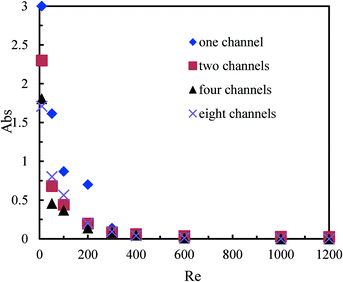 | ||
| Fig. 4 Comparison of the mixing performance between a single microchannel and the multichannel micromixers. | ||
Moreover, the collecting chamber affected the micromixing efficiency of the multichannel micromixers. According to the experimental observation, the whole collecting chamber could not be fully filled with the liquid mixture, in which some remaining air was present, and hence, a gas–liquid interface formed, as shown in Fig. 5. The flow domain in the collecting chamber for the single microchannel (Fig. 5a) was somewhat larger than that in the multichannel micromixers with 2, 4 and 8 channels (Fig. 5b–d). Therefore, the flow velocities of fluids in the flow domain of the collecting chamber of these multichannel micromixers were higher than those for the single microchannel at the same mean Reynolds numbers determined for each parallel channel. The increase in flow rates in the flow domain of the collecting chamber resulted in higher local Reynolds numbers and more significant fluid disturbance, thus yielding better mixing performance. Even more important, the flow velocities in the outlet of the single microchannel were much lower than those in the outlets of the multichannel micromixers with 2, 4 and 8 channels. The fluid disturbance in the outlets of the multichannel micromixers with 2, 4 and 8 channels was more remarkable, and, consequently, higher mixing efficiency could be obtained as compared with the single microchannel.
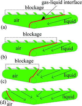 | ||
| Fig. 5 Flow domain and gas–liquid interface in the collecting chambers of single microchannel (a) and multichannel micromixers with 2, 4 and 8 channels (b–d). | ||
Effect of the micromixer position on the mixing performance
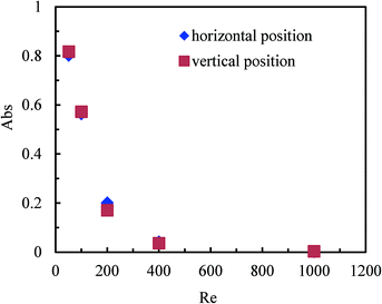
The position of mixers or reactors is an important factor in industrial production. A flexible position is advantageous for integrating the mixers with other unit operation equipment. For mixers and reactors with conventional dimensions, their positions usually have a great influence on the mixing efficiency, and the gravity effect should be carefully considered in the reactor design. Fig. 6 shows the effect of the position of the multichannel micromixer with 8 parallel channels on the mixing performance, with the vertical and horizontal positions to be chosen. It can be seen that the mixing performance does not depend on whether the vertical or horizontal micromixer position is selected. In other words, the gravity effect has only insignificant impact on the mixing performance in multichannel micromixers. These results clearly indicate that the multichannel micromixers can be placed in arbitrary positions without changing the micromixing efficiency. This is beneficial for the implementation of multichannel micromixers in practical applications. The gravity effect on the mixing performance in microstructured devices can be neglected due to their small characteristic dimensions. Pohar et al.42 reported analogous results for the immiscible liquid–liquid two-phase flow in microchannels.Effect of channel blockage on the mixing performance of multichannel micromixers
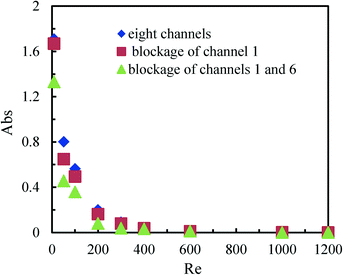
The synthesis of nanoparticles or microparticles and the production of emulsions in micromixers have attracted growing interest from both academia and industry.13 In these processes, precipitation on the microchannel walls sometimes occurs and the accumulation of solid particles can finally result in channel blockage.43 We, therefore, investigated the effect of channel blockage on the mixing performance of the multichannel micromixer with 8 channels.Fig. 7 shows the mixing performance in the multichannel micromixer with the blockage of channel 1 and with the simultaneous blockage of channels 1 and 6. Unexpectedly, it was found that the channel blockage did not reduce the micromixing efficiency compared with the multichannel micromixer without any channel blockage. Moreover, it was even somewhat increased, especially for the multichannel micromixer with the blockage of channels 1 and 6 at low Reynolds numbers. This may be attributed to the fact that constructal distributors ensure good fluid redistribution. Thus, higher actual flow rates and fluid disturbance are achieved in the open channels of the multichannel micromixers with blockages when compared to the multichannel micromixers without blockages operated under the same inlet volumetric flow rates.
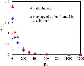
The mixing performance of the multichannel micromixer with the blockages of outlets 1 and 2 in distributor 1 was also investigated. Fig. 8 compares the mixing performance of the multichannel micromixer without blockages and the multichannel micromixer with the blockages of outlets 1 and 2 in distributor 1. It can be seen that the micromixing efficiency was reduced in the case of the distributor outlet blockages at low flow rates. Solution B could be equally distributed among the eight parallel channels via distributor 2 without the outlet blockages. However, solution A could not flow through channels 1 and 2 due to the blockages of outlets 1 and 2 in distributor 1. Fluid uniformity among the parallel eight channels was broken and the mixing process deteriorated. As a result, the amount of H+ in solution A in channels 1–6 was in excess, and more triiodide complex was produced. These results further demonstrate the important role of the distributors in the numbering-up of single microchannels.
In order to characterise the fluid distribution in the distributors with outlet blockages, we carried out CFD simulations using the commercial tool COMSOL Multiphysics (see a detailed description in our previous work40). To quantify flow non-uniformity in distributor 1 with the blockage of outlet 1, the relative deviation (RDi) and the standard deviation (SD) between the actual velocity magnitude at each non-blocked outlet and the average velocity value for all seven non-blocked outlets at uniform distribution are defined as follows:
 | (1) |
 | (2) |
Fig. 9 shows the velocity magnitude and RDi at each non-blocked outlet of distributor 1 with the blockage of outlet 1 at different inlet flow rates in the distributor. It can be seen that the velocity magnitude and RDi at outlet 2 is obviously higher than those of the other six non-blocked outlets. The symmetry of the bifurcation configuration that generated outlets 1 and 2 was broken and the fluid could only flow through outlet 2 in this bifurcation zone because of the blockage of outlet 1. Encouragingly, the velocity magnitude at outlets 3–8 was similar (Fig. 9a) and the corresponding RD did not exceed ±12% (Fig. 9b) for three different inlet flow rates. The value of SD for the seven non-blocked outlets was lower than 15% for the inlet flow rates, varying between 3–60 ml min−1. This deviation was mainly caused by the excessive flow rate at outlet 2. It is worth noting that the blockages of outlet 1 in distributor 1 and outlet 1 in distributor 2 were equivalent to the blockage of channel 1. The numerical results on the fluid distribution in distributor 1 with the blockage of outlet 1 can help to explain the higher mixing performance of the multichannel micromixer with the blockage of channel 1 than that of the multichannel micromixer without any channel blockage.
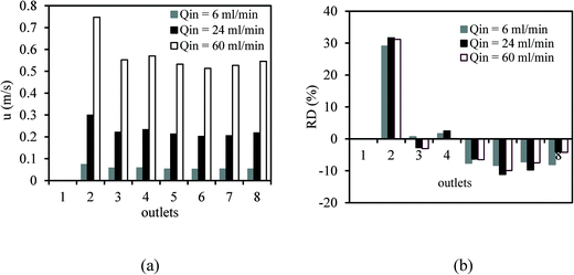 | ||
| Fig. 9 Velocity magnitude (a) and RDi (b) at each non-blocked outlet of distributor 1 with the blockage of outlet 1 at different inlet flow rates in distributor 1. | ||
Pressure drop characteristics in multichannel micromixers
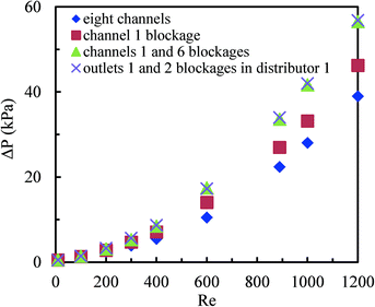
Fig. 10 shows the pressure drop in the multichannel micromixers with and without blockages. It was found that channel blockages remarkably increased the pressure drop when the average Reynolds number in the parallel channels was higher than 400. More channel blockages resulted in a higher pressure drop. The channel blockages prohibited the fluids to flow through the blocked channels and led to higher Reynolds numbers in other channels. Furthermore, the pressure drop in the multichannel micromixer with the blockages of channels 1 and 6 was very close to that in the multichannel micromixer with the blockages of outlets 1 and 2 in distributor 1. These results further indicate that the excellent fluid redistribution can be ensured via the constructal distributors when the blockages arise in the channels or in the outlets of distributors.The comparison between the pressure drop in a single microchannel and in the multichannel micromixer with 8 channels is shown in Fig. 11. It can be seen that the pressure drop in the multichannel micromixer is higher than that in the single microchannel. This trend is more pronounced when the average Reynolds number is larger than 400. In addition to the pressure drop arising from the frictional resistance, there was local pressure drop due to the fluid splitting and re-combining in the distributors and in the collecting chamber for the multichannel micromixer. Such a local pressure drop also arises in other types of fluid distributors.44 Apparently, the local pressure drop resulted in the difference in the values of the single microchannel and of the multichannel micromixer. The role of the local pressure drop in the multichannel can be neglected at low Reynolds numbers, but it becomes larger with increasing Reynolds numbers.
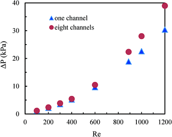 | ||
| Fig. 11 Comparison of the pressure drop between the single microchannel and the multichannel micromixer with 8 channels. | ||
The relationship between specific energy dissipation and mixing performance in multichannel micromixers
The specific energy dissipation (ε) in a channel is proportional to the pressure drop: | (3) |
| M = ρ·V | (4) |
Fig. 12 shows the relationship between the specific energy dissipation and the mixing performance of the 8-channel multichannel micromixers with and without channel blockages. It can be seen that the micromixing performance improves with growing specific energy dissipation in the multichannel micromixers, and the relationship between the light absorption and the energy dissipation approximately satisfied the power function:
Abs = 0.3![[thin space (1/6-em)]](https://www.rsc.org/images/entities/char_2009.gif) exp(−0.013ε) exp(−0.013ε) | (5) |
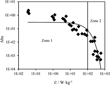 | ||
| Fig. 12 Relationship between the specific energy dissipation and the mixing performance of the multichannel micromixers. | ||
As shown in Fig. 12, the specific energy dissipation in the multichannel micromixers varied over several orders of magnitude (10−2–103 W kg−1) depending on the flow rate and the pressure drop. The whole zone of Fig. 12 can be subdivided into Zone 1 and Zone 2. In Zone 1 (ε < 102 W kg−1), the mixing process is mainly controlled by molecular diffusion being far from the ideal micromixing condition. In Zone 2 (ε > 102 W kg−1), the mixing process is dominated by the convection resulting from the combined effect of the zigzag channel structures and the high flow rates, with micromixing approaching an ideal performance. Furthermore, the channel blockages result in fluid redistribution in the multichannel micromixer, and, compared to the micromixer without channel blockages under the same inlet volumetric flow rates, they may facilitate mixing due to the transition from molecular diffusion to convection. Higher micromixing performance in the multichannel micromixers is achieved at the expense of higher specific energy dissipation. Therefore, both the mixing performance and the specific energy dissipation should be considered simultaneously when choosing a suitable operational zone for the mixing process in multichannel micromixers.
Conclusions
The micromixing performance in zigzag microchannels was investigated experimentally based on the Villermaux–Dushman reaction system. The micromixing performance in microchannels was evaluated by measuring the light absorption of effluent at the micromixer outlet. The concentration of sulphuric acid for the Villermaux–Dushman reaction was adjusted in order to improve the detection sensitivity of the mixing performance in microchannels at commonly used Reynolds numbers. Numbering-up was realised within the same multichannel micromixer including 8 parallel channels by selectively blocking the channels with sealing grease. The micromixing performance in these micromixers reached higher quality than that in a single microchannel, because the fluid disturbance in the collecting chambers and the outlets of the micromixers was higher than that in the collecting chamber and the outlet of the single microchannel. The results showed that the flat constructal distributors with bifurcation configurations could provide excellent flow uniformity for the parallel channels of multichannel micromixers, while the collecting chamber and the outlet also played an important role in the numbering-up of the microchannels. The micromixing performance was independent of the micromixer position, which is an advantageous property for linking the multichannel micromixers to other equipment units in industry.Furthermore, the effect of channel blockage on the mixing performance in the multichannel micromixer was studied. Channel blockage somewhat increased the micromixing efficiency due to higher Reynolds numbers arising from the fluid redistribution effect of the constructal distributors. However, the channel blockage resulted in a higher pressure drop and hence higher specific energy dissipation in the multichannel micromixer. The role of the local pressure drop in the multichannel can be neglected at low Reynolds numbers, but it becomes substantial with increasing flow rates. The micromixing efficiency grows with increasing specific energy dissipation in the multichannel micromixers, and the relationship between the light absorption and the energy dissipation approximately satisfies the power function. In the case of specific energy dissipation smaller than 102 W kg−1, the micromixing performance in the multichannel micromixers is controlled by molecular diffusion. In contrast, it is dominated by convection when the specific energy dissipation is higher than 102 W kg−1.
Acknowledgements
Yuanhai Su is grateful to the Alexander von Humboldt Foundation and the National Natural Science Foundation of China (no. 21225627) for financial support.References
- B. Palanisamy and B. Paul, Chem. Eng. Sci., 2012, 78, 46–52 CrossRef CAS PubMed.
- U. Engelmann and G. Schmidtnaake, Macromol. Theory Simul., 1994, 3, 855–883 CrossRef CAS.
- C. Beck, S. V. Dalvi and R. N. Dave, Chem. Eng. Sci., 2010, 65, 5669–5675 CrossRef CAS PubMed.
- B. Nienhaus, in Crystallization: Basic Concepts and Industrial Applications, 2013, pp. 247–274 Search PubMed.
- M. Giridhar and K. Krishnaiah, Bioprocess Eng., 1993, 9, 263–269 CrossRef CAS.
- S. Mitic and S. de Vries, in Comprehensive Biophysics, 2012, vol. 1, pp. 514–532 Search PubMed.
- Y. Ying, G. Chen, Y. Zhao, S. Li and Q. Yuan, Chem. Eng. J., 2008, 135, 209–215 CrossRef CAS PubMed.
- J. R. Bourne, Chem. Eng. Sci., 1982, 38, 5–8 CrossRef.
- J. R. Bourne, Org. Process Res. Dev., 2003, 7, 471–508 CrossRef CAS.
- M. N. Kashid, A. Renken and L. Kiwi-Minsker, Chem. Eng. Sci., 2011, 66, 3876–3897 CrossRef CAS PubMed.
- B. P. Mason, K. E. Price, J. L. Steinbacher, A. R. Bogdan and D. T. McQuade, Chem. Rev., 2007, 107, 2300–2318 CrossRef CAS PubMed.
- P. L. Mills, D. J. Quiram and J. F. Ryley, Chem. Eng. Sci., 2007, 62, 6992–7010 CrossRef CAS PubMed.
- S. Marre and K. F. Jensen, Chem. Soc. Rev., 2010, 39, 1183–1202 RSC.
- Y. Chen, Y. Zhao, M. Han, C. Ye, M. Dang and G. Chen, Green Chem., 2013, 15, 91–94 RSC.
- Y. Zhao, G. Chen and Q. Yuan, AIChE J., 2007, 53, 3042–3053 CrossRef CAS.
- J. T. Adeosun and A. Lawal, Chem. Eng. Sci., 2009, 64, 2422–2432 CrossRef CAS PubMed.
- W. Ehrfeld, K. Golbig, V. Hessel, H. Löwe and T. Richter, Ind. Eng. Chem. Res., 1999, 38, 1075–1082 CrossRef CAS.
- F. Schönfeld, V. Hessel and C. Hofmann, Lab Chip, 2004, 4, 65–69 RSC.
- Y. Su, G. Chen and Q. Yuan, Chem. Eng. Sci., 2011, 66, 2912–2919 CrossRef CAS PubMed.
- B. J. Kim, S. Y. Yoon, K. H. Lee and H. J. Sung, Exp. Fluids, 2009, 46, 85–95 CrossRef PubMed.
- V. Hessel, H. Löwe and F. Schönfeld, Chem. Eng. Sci., 2005, 60, 2479–2501 CrossRef CAS PubMed.
- C.-Y. Lee, C.-L. Chang, Y.-N. Wang and L.-M. Fu, Int. J. Mol. Sci., 2011, 12, 3263–3287 CrossRef CAS PubMed.
- V. Kumar, M. Paraschivoiu and K. D. P. Nigam, Chem. Eng. Sci., 2011, 66, 1329–1373 CrossRef CAS PubMed.
- J. Aubin, M. Ferrando and V. Jiricny, Chem. Eng. Sci., 2010, 65, 2065–2093 CrossRef CAS PubMed.
- M. Hoffmann, M. Schlüter and N. Räbiger, Chem. Eng. Sci., 2006, 61, 2968–2976 CrossRef CAS PubMed.
- A. D. Stroock, S. K. W. Dertinger, A. Ajdari, I. Mezic, H. A. Stone and G. M. Whitesides, Science, 2002, 295, 647–651 CrossRef CAS PubMed.
- S.-S. Hsieh and Y.-C. Huang, J. Micromech. Microeng., 2008, 18, 065017 CrossRef.
- R. F. Ismagilov, A. D. Stroock, P. J. A. Kenis, G. Whitesides and H. A. Stone, Appl. Phys. Lett., 2000, 76, 2376–2378 CrossRef CAS PubMed.
- J. Yue, J. C. Schouten and T. A. Nijhuis, Ind. Eng. Chem. Res., 2012, 51, 14583–14609 CrossRef CAS.
- M. C. Fournier, L. Falk and J. Villermaux, Chem. Eng. Sci., 1996, 51, 5053–5064 CrossRef CAS.
- S. Li, J. Xu, Y. Wang and G. Luo, Chem. Eng. Sci., 2007, 62, 3620–3626 CrossRef CAS PubMed.
- Y. Su, G. Chen and Q. Yuan, AIChE J., 2012, 58, 1660–1670 CrossRef CAS.
- A. Kölbl and M. Kraut, AIChE J., 2011, 57, 835–840 CrossRef.
- A. Kölbl and S. Schmidt-Lehr, Chem. Eng. Sci., 2010, 65, 1897–1901 CrossRef PubMed.
- A. Kölbl, M. Kraut and K. Schubert, AIChE J., 2008, 54, 639–645 CrossRef.
- A. Kölbl, M. Kraut and R. Dittmeyer, Chem. Eng. Sci., 2013, 101, 454–460 CrossRef PubMed.
- A. Kölbl, M. Kraut and K. Schubert, Chem. Eng. J., 2010, 160, 865–872 CrossRef PubMed.
- E. Kamio, T. Ono and H. Yoshizawa, Lab Chip, 2009, 9, 1809–1812 RSC.
- X. Guo, Y. Fan and L. Luo, Chem. Eng. J., 2013, 227, 116–127 CrossRef CAS PubMed.
- Y. Su, A. Lautenschleger, G. Chen and E. Y. Kenig, Ind. Eng. Chem. Res., 2014, 53, 390–401 CrossRef CAS.
- M. Engler, N. Kockmann, T. Kiefer and P. Woias, Chem. Eng. J., 2004, 101, 315–322 CrossRef CAS PubMed.
- A. Pohar, M. Lakner and I. Plazl, Microfluid. Nanofluid., 2011, 12, 307–316 CrossRef.
- T. Noël, J. R. Naber, R. L. Hartman, J. P. McMullen, K. F. Jensen and S. L. Buchwald, Chem. Sci., 2011, 2, 287–290 RSC.
- M. Pan, Y. Tang, H. Yu and H. Chen, AIChE J., 2009, 55, 1969–1982 CrossRef CAS.
- N. Kockmann, Transport Phenomena in Micro Process Engineering, Springer, New York, 2007 Search PubMed.
| This journal is © The Royal Society of Chemistry 2015 |

