
Direct ionic liquid extractant injection for volatile chemical analysis – a gas chromatography sampling technique†
S. U.
Mokhtar
ab,
S.-T.
Chin
a,
R.
Vijayaraghavan
c,
D. R.
MacFarlane
c,
O. H.
Drummer
d and
P. J.
Marriott
*a
aAustralian Centre of Research on Separation Science, School of Chemistry, Faculty of Science, Monash University, Clayton, VIC 3800, Australia. E-mail: Philip.marriott@monash.edu; Fax: +61 3 99058501; Tel: +61 3 99059630
bFaculty of Chemical Engineering and Natural Resources, Universiti Malaysia Pahang, 26300 Pahang, Malaysia
cSchool of Chemistry, Faculty of Science, Monash University, Clayton, VIC 3800, Australia
dDepartment of Forensic Medicine, Monash University, Clayton, VIC 3800, Australia
First published on 23rd October 2014
Abstract
A green sampling approach by direct injection of ionic liquid (IL) solvent containing a variety of analytes using programmable temperature vaporisation (PTV) injection with gas chromatography (GC) is presented. The method was developed using test mixtures of n-alkanes, n-alcohols and polyaromatic compounds, whilst back extraction of isolated compounds from the IL with organic solvent is not required. In the final method, 2 μL of IL, 1-butyl-3-methylimidazolium bis(trifluoromethylsulfonyl)amide containing analytes, was diluted to different volumes (ranging from 10 to 70%) with solvent then injected into the system. Several PTV injector parameters were investigated to ensure analyte volatilisation and transfer into the GC column. Concentration calibration curves (10–150 μg mL−1 and 10–100 μg mL−1 for n-alkanes and n-alcohols, respectively) were constructed, and showed addition of IL increased the peak area of each analyte, with good precision, and acceptable linearity with correlation coefficient, r2 > 0.93. This method was successfully applied in analysis of a polynuclear aromatic hydrocarbons (PAHs) mixture, with addition of IL in the mixture and suitable operation of the PTV injector. The method was also applied to eucalyptus leaf essential oil compounds as a test sample in a single drop microextraction experiment.
Introduction
Ionic liquids (ILs) are a new class of designer solvent that has accelerated research in extraction technology. They are organic salts which are liquid at room temperature, consisting of appropriate anions and cations.1 They possess unique properties such as low volatility, high viscosity compared with conventional solvents, good thermal stability at elevated temperature, variable polarities, designable chemical characteristics, with good solubility for organic and inorganic compounds, and favourable environmental properties.2,3 ILs have attracted extensive attention and gained popularity in many areas of analytical chemistry such as ILs as stationary phases in gas chromatography (GC),4 extraction solvents, dissolution solvents and separation media.5 As stationary phases in GC, whilst they are very polar, they can be tailored in their polarity, and are suitable for a number of different applications.6 ILs are attractive alternatives to conventional extraction solvents7 employed in sample preparation for different type of solutes, from polar to non-polar. They can be considered as a ‘green solvent’ because of their property of low vapour pressure at room temperature compared to organic solvents; this property may reduce the release of substances to the environment.8ILs have been employed as extractants to preconcentrate analytes from aqueous phases, such as in liquid–liquid extraction (LLE),9,10 solid phase extraction (SPE),11 solid phase microextraction (SPME),12,13 single drop microextraction (SDME),14,15 solvent bar microextraction (SBME),16 hollow-fiber liquid phase microextraction (HF-LPME),17 dispersive liquid microextraction (DLLME)18,19 and static headspace extraction-gas chromatography (SHE-GC).20 They are frequently applied to organic compound analysis in environmental, pharmaceutical, biomedical and food samples. A recent study combined two extraction techniques – DLLME and micro-solid phase extraction (μ-SPE) – to extract antidepressant drugs from water samples. 1-Hexyl-3-methylimidazolium tris(pentafluoroethyl)trifluorophosphate was employed for DLLME with high performance liquid chromatography (HPLC) analysis.21 The tunability of ILs allows suitable choices to replace conventional solvents.22 They can be used as dissolution solvent for the headspace gas chromatography analysis of residual solvents in pharmaceutical matrices.23 Many of these microextraction procedures may be considered as green alternatives to classical extraction methods.
GC is attractive for trace analysis of e.g. environmental, petrochemical, essential oil and biological samples. Although each GC component (injector, column and detector) is important for appropriate method development, of interest here is the injection port, since transfer of an IL solvent into the injector is a non-traditional approach to sample introduction – usual solvents are low molar mass volatile organics; an IL injection solvent requires attention to suitable operation parameters. Of various injection techniques – split/splitless, on-column and programmed temperature vaporisation (PTV) techniques – the latter offers useful analytical flexibility; method sensitivity can be increased by using this injector for example with large volume injection.24 Applications of the PTV inlet for sample introduction are extensive. In static headspace GC, it can be used as an interface between headspace sampling and the column, with use of sorbent traps between the sampling vial and the GC, and use of GC as a direct interface between headspace and MS.20 Direct introduction of cooked ham into a PTV combined with multidimensional gas chromatography (MDGC) assisted detection of radiolytic hydrocarbon formation during irradiation. This approach eliminated potentially labour- and solvent-intensive sample preparation steps.25 The PTV injector can decrease analyte discrimination during injection, provide better recoveries of thermally labile compounds, and increase the detectability of analytes via large volume introduction of liquid samples (e.g. up to 100 μL or more).26 To apply ILs as an extraction solvent, the PTV injector was considered a suitable approach. Several parameters need consideration to introduce the analytes into the column, according to the usual parameters for PTV. Several prior studies reported static headspace sampling from an IL matrix coupled with the PTV inlet, but did not employ injection of the IL solvent in that study.27,28
Since ILs typically have low volatility and high viscosity, they are incompatible with introduction into the GC column, which might lead to coating of the column with involatile material, and may cause deleterious effects such as blocking the analytical column channel.7 For this reason HPLC may be chosen when using IL-DLLME for compound analysis.2 The PTV liner should be regularly cleaned to prevent decomposition products appearing as chromatographic ghost peaks, and/or to remove accumulated material. Development of a removable interface,29 which would allow IL to be periodically removed from the inlet after volatilised analytes are transferred into the GC column, is a possible method refinement. Another study employed an in-needle approach to retain the IL sorbent in the needle whilst permitting analyte volatilisation.30 In the present study, the green chromatography attribute of direct injection31 is used to introduce analytes into the GC system with IL used as the extraction medium. Thus, analyte need not be back extracted from the IL using a GC-compatible solvent, so this extended sample preparation step can be omitted when performing GC-PTV analysis, giving a greener outcome. This report investigates the use of ILs for direct introduction into the PTV without damaging the analytical column, and explores the feasibility of PTV injection for retaining the IL in the liner whilst transferring analyte into the column. An example of IL as extractant medium is included. Up to early 2014, to the best of our knowledge no paper published the direct injection of ILs in programmed temperature vaporisation (PTV) as in this study. As an application of this method, IL was used as the extractant to extract essential oil compounds from eucalyptus leaves using the IL-SDME technique.
Results and discussion
Optimisation of PTV injection for direct introduction of IL in GC-MS
To effectively transfer analyte to the column the PTV is expected to be influenced by several factors including the adjuvant solvent's (i.e. solvent added to the IL to decrease its viscosity if required) boiling point, initial injector temperature, solvent venting time, inlet heating rate, split ratio, final inlet temperature, and the analyte boiling points. Adjustment of these factors is important to ensure that solvent is vaporised and eliminated from the PTV via the vent line, that IL does not enter the column nor decompose, and that analyte is effectively (100%) transferred to the column under splitless conditions. The liner comprises a frit in the middle, which is used in this work to assist in retaining injected IL within the liner. Deactivated glass wool is also inserted into the liner in order to improve quantification in splitless injection for samples containing involatile materials and to improve the solute transfer to the column.32 Solvent venting prevents residual or adjuvant organic solvent from reaching the column, with only analytes introduced into the column.33 Vallecillos et al.34 developed an IL-SDME method with gas chromatography-ion trap-tandem mass spectrometry (GC-IT-MS/MS) with a large diameter liner (3.4 mm ID), a piece of glass wool and guard column to avoid introduction of ILs into the analytical GC column. PTV injection was also applied, but operated at constant 280 °C compared with this present method where temperature programmed heating is performed to achieve better chromatographic performance.In this study, the initial inlet temperature was optimised in order to ensure the IL and analyte is retained in the liner, and solvent leaves the system through the split exit. The temperature must be set at or near the adjuvant solvent's boiling point, or typically between 0 and 50 °C. DCM is used as solvent to dilute the analytes (and is compatibility with the IL), so the temperature was set at 50 °C. An appropriate solvent vent time of 2 min was determined, in order to evaporate and eliminate solvent via the split exit.35 The column temperature was held slightly below the initial PTV temperature in order to be below the dew point of the carrier gas–vapour mixture leaving the injector.36 The final inlet temperature was adjusted to between 200–300 °C depending on the injected analytes. 250 °C is an acceptable temperature to volatilise most analytes, however this must be optimised to ensure effective vaporisation. Conventional splitless injection usually requires the vent to be opened after a period in order to flush out residual analyte, which may otherwise remain for an extended period in the injector, and thus only slowly enter the column.37 The splitless period should take into account this time, after analyte is vaporised. If the vent is opened before analyte is largely transferred to the column, the analyte will be preferentially flushed out the vent. The detector response is the only functional record that is available to monitor the efficiency of this process.
The following estimation of mass balance for retention of IL in the injector was conducted. 2 μL of [BMIM][TfSA] (1.43 g mL−1) is equal to 2.86 mg. By direct measurement, manual syringe delivery of 2 μL of IL gave a mass of 2.60 ± 0.10 mg. Mass balance of IL in GC with PTV injection was determined by taking the mass of the liner (with glass wool) before and after injection of 2 μL of IL into the PTV, with heating of the liner to 300 °C. This step was repeated ten times. The residual mass increase for each separate injection was determined to be 2.60 ± 0.17 mg, indicating the IL was successfully retained in the liner. As a procedural approach, the liner was replaced every 5 injections of IL.
Effect of IL for analysis of polar and apolar analytes
To investigate the extraction efficiency of ILs for polar and apolar analytes, n-alkanes and n-alcohols were used in this study. From stock solution of 1000 μg mL−1n-alkanes (C18, C19 and C22) and n-alcohols (octanol, nonanol, decanol) diluted with dichloromethane (DCM), 0.1 mL of each analyte was transferred into a 1 mL vial. Then, a given volume of [BMIM][TfSA] was spiked into the sample solution. Selected alkanes and alcohols were chosen since the effect of IL on delivery of analyte to the column was to be tested. The total volume and concentration of the sample solution was maintained at 1 mL and 100 μg mL−1, respectively. The sample solution was vortexed for 1 min to ensure the IL is well homogenised with the analytes and solvent. The PTV condition of this study can be seen in ESI Fig. S1.†2 μL of [BMIM][TfSA] without any analyte was injected into the system. No peak was obtained at the detector (data not shown), and so it was assumed that no IL degradation products were produced. Then, n-alkanes and n-alcohols at 100 μg mL−1 with addition of 0.2 mL (20%) [BMIM][TfSA] were analysed and indicated that the analytes are properly volatilised without any additional/degradation peaks from IL (ESI Fig. S2 and S3†). In this study, GC data for 100 mg L−1 DCM solutions of both alkanes and alcohols (chromatograms not shown) without addition of IL were also analysed as control experiments. The results indicated that IL has the ability to slightly enhance the sensitivity as extractant for different polarity analytes and both apparently were well transferred to the column. Since the solvent was slowly evaporated and vented through the split vent at the first stage, this causes enrichment of analytes in the injector for transfer to the column.33
In addition, solvent choice is a concern in consideration of green chemistry because one of the 12 principles of green analytical chemistry proposes the use of less toxic and environmentally burdensome chemicals and solvents.38 Techniques such as IL-DLLME, involve many lengthy steps, especially to optimise extraction solvent, disperser solvent, volume of solvent, pH, time and ionic strength.39,40 In order to overcome these method demands, direct injection of the samples with IL is more efficient, provided the IL matrix is transparent to, and is non-interfering towards, the chromatographic column. Several methods have been developed such as a removable interface that enables the introduction of the extracted analytes from SDME into the GC system.29 However, after only three injections, the method caused GC column interference, and saturation of the injector packing material. Also, there are limitations for volume of IL injected and the length of the removable unit. A thermal desorption device with an inner tube was designed for the direct use of IL-SDME-GC41 but the setup is complicated and tedious since many parameters needed to be considered. Here, the PTV injector requires little method development once set up, and little maintenance other than checking the liner and cleaning or replacing the liner and the glass wool, for instance after 5–10 injections, in order to remove build-up of IL.
Effect of IL volume on analyte response
Fig. 1 shows the peak areas of alkanes and alcohols without addition of IL (i.e., 0% of IL) and also with addition of IL in the sample solution, from 10%–70% IL. The peak area is about constant compared with the blank sample solution up to about 20%–40% for both analytes. The signal-to-noise (S/N) for both alkanes and alcohols also increases with an increase in peak area, demonstrating improved sensitivity of the method with addition of IL. However, the peak area decreases at IL% greater than 40%, remaining constant at larger IL% for alkanes, but further reducing for alcohols.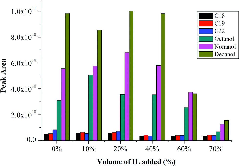 | ||
| Fig. 1 Effect of volume% of IL added on response of 100 μg mL−1n-alkanes and n-alcohols. | ||
Calibration curve linearity
Calibration curves were generated to investigate the linearity of detector response (peak area) versus concentration of analytes, with a constant 20% of [BMIM][TfSA]. Both alkanes (10, 50, 100 and 150 μg mL−1) and alcohols (10, 25, 50, 75, 100 μg mL−1) were prepared, and 2 μL of each analyte was injected in triplicate. Table 1 summarises the result of calibration curves obtained for both alkanes and alcohols, with RSD values. Acceptable linearity of the calibration curves was observed in the investigated concentration range with correlation coefficients (r2) of between 0.979–0.991 for alkanes and 0.937–0.996 for alcohols. The repeatability, described as percent RSD for triplicate experiments at 150 μg mL−1 for alkanes were in the range 3.6–13.7%, and at 10 μg mL−1 for alcohols were in the range 7.4–10.6%.| Analytes | Retention times (min) | Calibration range (μg mL−1) | Linearity, r2 | RSDb (%, n = 3) | |
|---|---|---|---|---|---|
| Without IL | With + 0.2 mL ILa | ||||
| a [BMIM][TfSA] as IL. b Relative standard deviation at concentration alkanes: 150 μg mL−1, alcohols: 10 μg mL−1. c Triplicate analyses at concentration 10, 50, 100, 150 μg mL−1. d Triplicate analyses at concentration 10, 25, 50, 75, 100 μg mL−1. | |||||
| C18 | 14.45 | 10–150c | 0.987 | 0.979 | 3.6 |
| C19 | 15.12 | 10–150c | 0.954 | 0.991 | 7.3 |
| C22 | 16.96 | 10–150c | 0.929 | 0.982 | 13.7 |
| C8–OH | 8.44 | 10–100d | 0.938 | 0.974 | 10.0 |
| C9–OH | 9.42 | 10–100d | 0.928 | 0.937 | 7.4 |
| C10–OH | 10.38 | 10–100d | 0.977 | 0.996 | 10.6 |
Method application with polyaromatic hydrocarbons (PAHs)
In order to study the reliability and feasibility of the method, it was applied to analytes which contain a broader volatility. A mixture of polyaromatic hydrocarbons (PAHs) was used, comprising 16 compounds diluted in MeOH. Table 2 shows the 16 PAH compounds, their concentration after dilution, and the retention times. The retention gap was removed even though theoretically it can accommodate the recondensed adjuvant solvent and prevent some IL which might migrate beyond the injector from entering the analytical column; no difference was observed with and without the pre-column. The small volume (2 μL) of sample injected into the injector, means the possibility for column damaged by the IL is low. It is necessary to ensure the quantity of remaining solvent is low to avoid flooding of the column.42| Elution order | Abbreviation | Compound | Concentrationa (μg mL−1) | B/Pb (°C) |
t
R![[thin space (1/6-em)]](https://www.rsc.org/images/entities/char_2009.gif) c (min) c (min) |
|---|---|---|---|---|---|
| a Concentration of each compound after dilution with methanol and with 0.1 mL of [BMIM][TfSA]. b Boiling point of each compound in PAH mixture. c Retention time of each compound in PAH mixture. | |||||
| 1 | NAP | Naphthalene | 200 | 218 | 7.78 |
| 2 | ACL | Acenaphthylene | 400 | 280 | 10.15 |
| 3 | ACE | Acenaphthene | 200 | 279 | 10.41 |
| 4 | FLU | Fluorene | 40 | 295 | 11.16 |
| 5 | PHE | Phenanthrene | 20 | 340 | 12.60 |
| 6 | ANT | Anthracene | 20 | 340 | 12.67 |
| 7 | FLT | Fluoranthene | 40 | 384 | 14.43 |
| 8 | PYR | Pyrene | 20 | 404 | 14.75 |
| 9 | CHR | Chrysene | 20 | 448 | 16.64 |
| 10 | B(A)A | Benzo(a)anthracene | 20 | 438 | 16.69 |
| 11 | B(K)F | Benzo(k)fluoranthene | 20 | 480 | 18.21 |
| 12 | B(B)F | Benzo(b)fluoranthene | 40 | 481 | 18.24 |
| 13 | B(A)P | Benzo(a)pyrene | 20 | 495 | 18.65 |
| 14 | IND | Indeno(1,2,3-CD)pyrene | 20 | 536 | 20.66 |
| 15 | DIB | Dibenz(a,h)anthracene | 40 | 524 | 20.78 |
| 16 | BEP | Benzo(g,h,i)perylene | 40 | 542 | 21.23 |
The PTV injector temperature must be adequate to volatilise the solvent and transfer the analytes, which have a relatively wide boiling point range, to the analytical column. This necessitated a further evaluation of heating rate, final inlet temperature, solvent vent time and splitless time (Fig. S4 in the ESI†).
Final inlet temperature for PTV
The initial PTV temperature was again set at 60 °C, a little below the solvent boiling point to allow slow evaporation of MeOH solvent in the injector. The final PTV temperature was set at 200 °C, 250 °C and 300 °C (Fig. S4(a) ESI†) under a heating rate of 200 °C min−1, reporting here just the first four solutes to check for successful transfer of all analytes into the column. From Fig. 2, 300 °C gave the highest response of each analyte. Sufficiently high temperature is important to ensure all the PAH compounds were properly vaporised and transferred into the column especially for compounds with higher boiling point. Sufficient time to ensure the vapours has adequate time to fully eliminate from the injector to the column under splitless condition is critical. Too low a final temperature, is insufficient to fully vaporise the solute, that lead to poor analyte transfer although they may be vaporised at low temperature, but in a relatively slow process. Consequently, any solutes still resident in the injector will be lost once the vent is re-opened. The time for vent open/close is important. At the limit, if the vent remains open, little analyte will transfer to the column and rather flush out the vent. At the other limit, if the vent is re-opened too early, then some PAH compounds which are still resident in the PTV will be flushed out through the vent; they will not be delivered to the column. The classical splitless sampling approach requires multiple injection liner gas volumes to successfully pass 100% of the sample vapour to the column. Usually, this is accompanied by solvent-effect solute trapping (the ‘Grob’ effect).37 The temperature profile in the PTV must be referenced to the boiling point of the analytes, in order to understand how readily the solvent enters the gas phase.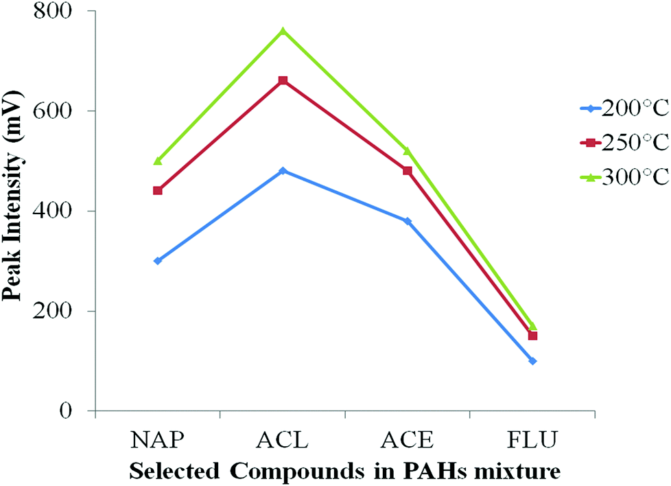 | ||
| Fig. 2 Effect of final inlet temperature on the peak intensity of four earliest PAH compounds. NAP: naphthalene, ACL: acenaphthylene, ACE: acenaphthene, FLU: fluorene. | ||
Heating rates for PTV
Interpretation also must consider the heating rate of the PTV injector; three different heating rates were set in this study, 100, 150 and 200 °C min−1 (Fig. S4(b) ESI†). Initial inlet temperature, final inlet temperature, vent open time and splitless time were maintained at 60 °C, 300 °C, 1 min and 5 min, respectively. Fig. 3 shows that the low heating rates (100 and 150 °C min−1) used to reach final inlet temperature did not result in higher responses compared to 200 °C min−1. Most of the compounds show the best response at heating rate 200 °C min−1 where they vaporise from the liner by “shock” heating.26 This assures good transfer of all analytes from the PTV into the column when the vent was closed (after 1 min). Slower heating rates can increase the residence time of each compound in the inlet. This heating rate will affect other parameters such as vent on/off time; it needs to be adjusted according to the applied heating rate and the vaporisation process to ensure all the analytes are properly transferred into the column.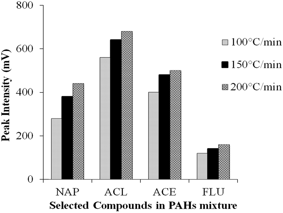 | ||
| Fig. 3 Effect of three different heating rates on the peak intensity of four earliest eluting PAH compounds. NAP: naphthalene, ACL: acenaphthylene, ACE: acenaphthene, FLU: fluorene. | ||
Vent open time at constant initial inlet temperature
Proper adjustment of vent times is important to minimise analyte loss. At constant 60 °C (initial inlet temperature), the vent was opened for certain durations; 0.40, 1.00, 2.00 and 3.00 min (Fig. S4(c) ESI†). The effect of longer vent open time (for solvent evaporation) at constant temperature on the response of each analyte is apparent. Other parameters such as heating rate, final inlet temperature, splitless time were maintained at 200 °C min−1, 300 °C and 5 min, respectively. The peak responses for most volatile compounds decreased with increasing the vent open time especially for the early-eluting solutes (Table 3). Extending the vent open time at constant temperature risks loss of volatile solute, so not only solvent will be flushed out the vent. For instance, beyond 0.40 min, the peak response for naphthalene decreased sharply. Chromatograms of the PAH mixture for 0.40 min and 3 min vent open can be seen in ESI (Fig. S5†). At a constant temperature of 60 °C, the naphthalene slowly volatilised and vented through the split exit with the solvent when increasing the vent open time from 0.40 min until 3 min. However, low volatility compounds did not show any difference while increasing the vent open time up to 3 min. Since 60 °C is insufficient to sweep less volatile compounds out the split exit, they are retained in the PTV until the internal PTV temperature is raised sufficiently to permit their vaporisation.| Analytes | Vent open time (min) | |||||||
|---|---|---|---|---|---|---|---|---|
| Peak intensity at constant T (60 °C) (mV) | Peak intensity at elevated T (mV) | |||||||
| 0.4 | 1.0 | 2.0 | 3.0 | 1 (60 °C) | 1.30 (160 °C) | 1.45 (210 °C) | 2 (260 °C) | |
| NAP | 540 | 460 | 240 | 100 | 460 | 260 | 220 | 200 |
| ACL | 900 | 790 | 800 | 600 | 790 | 760 | 650 | 190 |
| ACE | 600 | 590 | 590 | 460 | 590 | 500 | 425 | 70 |
| FLU | 260 | 200 | 190 | 160 | 200 | 180 | 170 | 25 |
Vent open time at elevated temperature
The effect of vent open time for solvent evaporation during the temperature ramp step (parameter (d) in Fig. S4 ESI†) can be seen in the Table 3. It shows the effect of vent open for extended times (into the period during which the PTV is temperature ramped), when the PTV reaches the following T: 1 min (60 °C); 1.30 min (160 °C); 1.45 min (210 °C); and 2 min (260 °C). The flow of carrier gas is maintained at 100 mL min−1 during these periods. Other parameters were maintained as earlier i.e. the initial and final inlet temperature at 60 °C and 300 °C, respectively, ramp at heating rate 200 °C min−1. For naphthalene, the peak response decreased drastically when vent was open beyond 1.30 min. Being the most volatile solute, naphthalene is largely vaporised when the PTV reaches 160 °C. Naphthalene loss commences at 160 °C even though it's boiling point is 218 °C (Table 2). Similarly, results for acenaphthylene, acenaphthene and fluorene demonstrate relatively large decreases when the vent is open for 2 min; solutes with boiling points in the range 270 to 340 °C are lost if the vent is open up to 260 °C. Less volatile solutes with higher molar mass and boiling point apparently are only vaporised into the entrained PTV gas flow beyond 260 °C, so are well transferred to the column.Splitless time for PTV
After the solvent evaporation, vent closure transfers sample vapour into the column with rapid heating; the column is the only exit from the vaporisation chamber. As stated by Grob, “solute transfer period” is an appropriate term.36 The period of the solute transfer depends whether split or splitless conditions are used, and is largely independent of injection volume. To determine the time required for acceptable transfer of the sample to the column, increasing duration of the splitless period was tested.43 Here, 3 min, 5 min and 10 min were set (corresponding to period (e) Fig. S4 ESI†); final inlet temperature, vent open time, and heating rate were maintained at 300 °C, 1 min and 200 °C min−1, respectively. Fig. 4 illustrates that 5 min is generally adequate to transfer less volatile compounds from injector to analytical column at 300 °C upper PTV setting. However, in some instances of rather nonvolatile compounds, such as from benzo(k)fluoranthene, peak intensity still increases up to 10 min splitless time. Under such circumstances, the oven T program should not commence until all solute has been fully transferred to the column.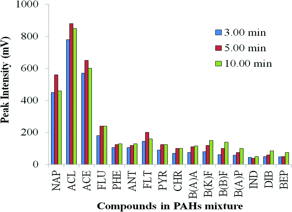 | ||
| Fig. 4 Effect of solute transfer period under splitless condition. | ||
Effect of different volumes of IL added to the PAH mixture
In order to investigate the effect of quantity of IL in the injected solution, different amounts of [BMIM][TfSA] were spiked into the analytes, and diluted with methanol. Four sets of PAH mixtures were prepared and vortexed with addition of 0%, 20%, 40% and 60% of [BMIM][TfSA]. The acceptable condition of PTV operation: initial and final inlet temperature at 60 °C and 300 °C, respectively, ramp at heating rate 200 °C min−1, vent open for 0.40 min (for solvent evaporation) and splitless time for 10 min were used, with the same oven temperature programme. It is noted (Fig. 5) that addition of IL in the sample mixture increases the peak response of early-eluting analytes compared to 0% IL. Generally about 40% of [BMIM][TfSA] added resulted in the highest response for each compound. It appears addition of IL can enhance the response and the sensitivity of the PAH compounds, although the exact reason for enhancement is uncertain.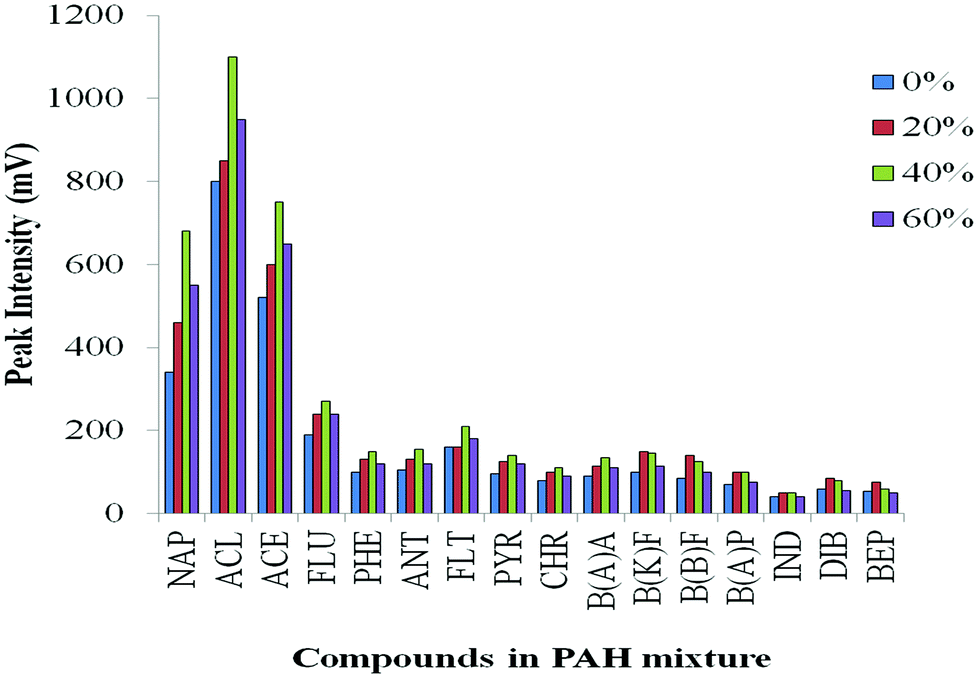 | ||
| Fig. 5 Effect of different volume% of [BMIM][TfSA] added into the PAH mixture on transfer of analyte to the column. | ||
Application to essential oil extracts
As a demonstration of the method, an application to the analysis of essential oil in eucalyptus leaves was conducted. By using the same GC-FID and acceptable condition of PTV injector condition as above, analysis commenced with injection of 2 μL of 100 μg mL−1 essential oil standards in acetone; α-pinene, 1,8-cineol and terpinen-4-ol. The eucalyptus leaves were obtained in Monash University, Clayton campus. The leaves were washed and dried at room temperature, then, ground to powder. Then, headspace SDME was performed in this work by using IL ([BMIM][TfSA]) as the droplet extractant. Leaf powder (0.5 g) was placed in a 10 mL glass vial sealed with a PTFE-faced septum cap. A 10 μL tapered needle GC microsyringe (Hamilton, Nevada, USA) was washed several times with an IL-miscible solvent to eliminate bubbles in the needle. The syringe with 2 μL of IL was inserted into the vial, clamped in place, and the needle tip located about 0.5 cm above the surface of the sample. The plunger was depressed, and a microdrop of IL was exposed to the headspace above the leaf powder at 70 °C for 20 min. After extraction, the drop was retracted into the needle and subsequently injected into the PTV inlet. Triplicate measurements were carried out in order to confirm reproducibility of the method and the syringe was held in the injector port a few seconds to make sure the droplet is well transferred into the liner. As a comparison, hexadecane solvent was contrasted with IL extractant.Fig. 6 depicts the GC-FID chromatogram of eucalyptus leaf powder after the HS-SDME method. It illustrated that HS-SDME successfully extracts compounds from the eucalyptus leaves, with 1,8-cineol the most abundant peak, and is extracted in similar amounts by both IL and hexadecane. The recovery of compounds extracted by IL appears to be more, compared to hexadecane; the latter results in an excessively large interfering peak in the GC trace due to extractant sorbent. It appears that partitioning into the IL is similar to that for the organic sorbent. Increasing the extraction temperature from room temperature (RT) to 70 °C increased the peak intensity, with more peaks observed in the chromatogram, especially for the less volatile sesquiterpenes at about 10 min retention. The higher T increases the headspace concentration of the less volatile essential oil compounds.44,45 Similar observations can also be observed with increased extraction time, with increased recovery as the exposure time of the IL microdrop increases. By contrast, the hexadecane microdrop cannot retain on the tip of needle for an extended time at 70 °C, due to slow evaporation and poor recoveries. Three replicate analyses of IL-HS-SDME produced essentially equivalent chromatographic data, indicating acceptable reproducibility. Few studies discuss the IL-SDME-GC technique, presumably because of the nonvolatility of IL. Alternative methods involved a homemade small glass tube in the injector,46 reported in combination with hydrodistillation,47 used a modified GC liner48 or a designed injector port attached to the GC.49
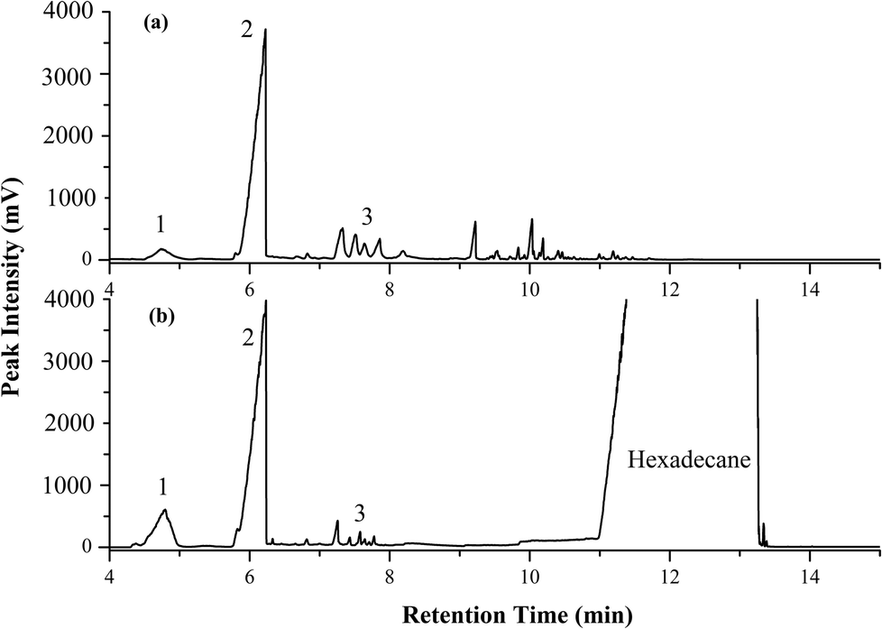 | ||
| Fig. 6 GC chromatogram of eucalyptus leaf powder with (a) IL-SDME at 70 °C for 20 min and (b) SDME with hexadecane sorbent at 70 °C for 10 min. Peak 1: α-pinene; Peak 2: 1,8-cineol; Peak 3: terpinen-4-ol. | ||
Fig. 6(b), hexadecane extractant results in minimum overlap with major extracted components since hexadecane elutes from about 11–13 min. More volatile extractants, such as toluene, hexane, DCM etc. evaporate too readily from the hanging drop on the syringe needle. Some sorption solvents such as 2-dodecanol mask extracted solutes. The absence of interfering peaks due to IL is an attractive property on this experiment. The capability of IL showed that IL-SDME is able to extract more compounds from eucalyptus leaves, and provides reproducible extraction compared to hexadecane.
Experimental
Chemicals and reagents
Ionic liquid 1-butyl-3-methylimidazolium bis(trifluoromethylsulfonyl)amide ([BMIM][TfSA]) was synthesised at Monash University by mixing BMIM chloride (4.16 g, 24 mmol; Sigma Aldrich) with LiTfSA (6.85 g, 24 mmol; 3M Fluorad, USA) in 40 mL aqueous medium. The mixture was stirred for 1 h in an excess (50 mL) of DCM added and poured into a separating funnel and shaken. The organic layer was separated and evaporated to dryness under reduced pressure to recover the IL.50 GC grade solvent DCM and methanol were purchased from Merck Chemical Co (Merck, KGaA, Darmstadt, Germany). Stock solutions of n-alkanes (octadecane C18, nonadecane C19 and docosane C22) as representative apolar compounds and n-alcohols (octanol, nonanol and decanol) as representative polar compounds were prepared in DCM at a concentration of 10 mg mL−1 and stored at 4 °C. Working solutions were prepared by diluting stock solutions with DCM (called here an adjuvant solvent), and with different proportions of IL added. An EPA method 610 polynuclear aromatic hydrocarbons (PAHs) mixture was purchased from Sigma Aldrich, comprising 16 compounds at different concentrations, as an application in this study. The mixture was diluted ten times from the stock solution with methanol. Then, 0.1 mL of PAH-MeOH sample was added with varying proportions of IL, 20% (0.1 mL), 40% (0.2 mL) and 60% (0.3 mL) to form 0.5 mL of sample mixture.Instrumentation
A further instrument – a Varian 3800 GC fitted with a flame ionisation detector – was also used. The GC was equipped with a BR-5 ms (15 m × 0.25 mm I.D. × 0.25 μm df) column and programmable temperature vaporisation (PTV) injector. Helium was used as a carrier gas at a flow rate of 1.5 mL min−1. The oven temperature was programmed as follows: 3 min at 50 °C to 280 °C at 15 °C min−1 (hold for 10 min), with detector temperature of 280 °C; total analysis time 28.33 min.
Conclusion
The present study demonstrated the feasibility of using the PTV injector as an interface to introduce an IL extraction matrix in a number of different modes into a GC instrument. IL may be used in a single-drop microextraction experiment, or as a bulk extraction material. Direct injection allows IL to be retained in the PTV injection zone, so the IL does not enter the analytical column nor compromise the performance of the analytical GC column. Using the PTV injector, [BMIM][TfSA] is successfully retained in the injector, and so the IL can be effectively used as a green extractant for polar and apolar analytes, then injected into the PTV; back-extraction from the IL is not required. This successfully eliminates time-consuming treatment of the IL extractant with a GC-compatible solvent, and can be considered as a green chromatography technique. This method was successfully applied to the analysis of PAH standard mixtures, and additionally applied to analyse essential oil compounds in eucalyptus leaves by using an IL-based HS-SDME method. A range of further studies can be considered where quantitative measurement of organic materials in an IL is required.Acknowledgements
The authors thank Bruker P/L for provision of GC-MS facilities. The authors acknowledge Australian Research Council ARC funding through Discovery Grant DP1310217 and DRM's Australian Laureate Fellowship. PJM acknowledges the award of a Discovery Outstanding Researcher Award by the ARC.Notes and references
- A. M. Stalcup and B. Cabovska, J. Liq. Chromatogr. Relat. Technol., 2004, 27, 1443–1459 CrossRef CAS PubMed.
- M. J. Trujillo-Rodríguez, P. Rocío-Bautista, V. Pino and A. M. Afonso, TrAC, Trends Anal. Chem., 2013, 51, 87–106 CrossRef PubMed.
- T. D. Ho, C. Zhang, L. W. Hantao and J. L. Anderson, Anal. Chem., 2014, 86, 262–285 CrossRef CAS PubMed.
- A. X. Zeng, S.-T. Chin, Y. Nolvachai, C. Kulsing, L. M. Sidisky and P. J. Marriott, Anal. Chim. Acta, 2013, 803, 166–173 CrossRef CAS PubMed.
- Z. Q. Tan, J. F. Liu and L. Pang, TrAC, Trends Anal. Chem., 2012, 39, 218–227 CrossRef CAS PubMed.
- M. D. Joshi and J. L. Anderson, RSC Adv., 2012, 2, 5470–5484 RSC.
- V. Vičkačkaite and A. Padarauskas, Cent. Eur. J. Chem., 2012, 10, 652–674 CrossRef PubMed.
- M. de la Guardia and S. Garrigues, Handbook of Green Analytical Chemistry, John Wiley & Sons Ltd., Chichester, 2012 Search PubMed.
- A. Rout and K. Binnemans, Dalton Trans., 2014, 43, 1862–1872 RSC.
- K. Kamiński, M. Krawczyk, J. Augustyniak, L. R. Weatherley and J. Petera, Chem. Eng. J., 2014, 235, 109–123 CrossRef PubMed.
- H. Yan, N. Sun, Y. Han, C. Yang, M. Wang and R. Wu, J. Chromatogr., A, 2013, 1307, 21–26 CrossRef CAS PubMed.
- F. Zhao, T. K. Ponnaiyan, C. M. Graham, C. A. Schall, S. Varanasi and J. L. Anderson, Anal. Bioanal. Chem., 2008, 392, 1271–1275 CrossRef CAS PubMed.
- A. Sarafraz-Yazdi and H. Vatani, J. Chromatogr., A, 2013, 1300, 104–111 CrossRef CAS PubMed.
- F. Q. Zhao, J. Li and B. Z. Zeng, J. Sep. Sci., 2008, 31, 3045–3049 CrossRef CAS PubMed.
- J. Jiao, D. H. Ma, Q. Y. Gai, W. Wang, M. Luo, Y. J. Fu and W. Ma, Anal. Chim. Acta, 2013, 804, 143–150 CrossRef CAS PubMed.
- Y. Zhang, R. Wang, P. Su and Y. Yang, Anal. Methods, 2013, 5, 5074–5078 RSC.
- X. Ma, M. Huang, Z. Li and J. Wu, J. Hazard. Mater., 2011, 194, 24–29 CrossRef CAS PubMed.
- R. N. Rao, S. S. Raju and R. M. Vali, J. Chromatogr., B: Anal. Technol. Biomed. Life Sci., 2013, 931, 174–180 CrossRef CAS PubMed.
- A. Mohammadi, R. Tavakoli, M. Kamankesh, H. Rashedi, A. Attaran and M. Delavar, Anal. Chim. Acta, 2013, 804, 104–110 CrossRef CAS PubMed.
- N. H. Snow and G. P. Bullock, J. Chromatogr., A, 2010, 1217, 2726–2735 CrossRef CAS PubMed.
- D. Ge and H. K. Lee, J. Chromatogr., A, 2013, 1317, 217–222 CrossRef CAS PubMed.
- J. G. Huddleston, H. D. Willauer, R. P. Swatloski, A. E. Visser and R. D. Rogers, Chem. Commun., 1998, 1765–1766 RSC.
- F. h. Liu and Y. Jiang, J. Chromatogr., A, 2007, 1167, 116–119 CrossRef CAS PubMed.
- A. K. Tsakalof, D. C. Gkagtzis, G. N. Koukoulis and C. S. Hadjichristodoulou, Anal. Chim. Acta, 2012, 709, 73–80 CrossRef CAS PubMed.
- C. Barba, G. Santa-María and M. M. Calvo, Food Chem., 2013, 139, 241–245 CrossRef CAS PubMed.
- M. Godula, J. Hajšlová, K. Maštouska and J. Křivánková, J. Sep. Sci., 2001, 24, 355–366 CrossRef CAS.
- J. L. Pérez Pavón, A. M. Casas Ferreira, M. E. Fernández Laespada and B. Moreno Cordero, J. Chromatogr., A, 2009, 1216, 6728–6734 CrossRef PubMed.
- J. L. Pérez Pavón, M. del Nogal Sánchez, M. E. Fernández Laespada and B. Moreno Cordero, J. Chromatogr., A, 2007, 1175, 106–111 CrossRef PubMed.
- E. Aguilera-Herrador, R. Lucena, S. Cárdenas and M. Valcárcel, Anal. Chem., 2008, 80, 793–800 CrossRef CAS PubMed.
- J. Zhang and H. K. Lee, Talanta, 2010, 81, 537–542 CrossRef CAS PubMed.
- J. Płotka, M. Tobiszewski, A. M. Sulej, M. Kupska, T. Górecki and J. Namieśnik, J. Chromatogr., A, 2013, 1307, 1–20 CrossRef PubMed.
- K. Grob Jr. and H. P. Neukom, Chromatographia, 1984, 18, 517–519 Search PubMed.
- M. Tobiszewski and J. Namieśnik, TrAC, Trends Anal. Chem., 2012, 35, 67–73 CrossRef CAS PubMed.
- L. Vallecillos, E. Pocurull and F. Borrull, Talanta, 2012, 99, 824–832 CrossRef CAS PubMed.
- H. G. J. Mol, H. G. Janssen, C. A. Cramers and U. A. T. Brinkman, TrAC, Trends Anal. Chem., 1996, 15, 206–214 CAS.
- K. Grob and Z. Li, J. High Resolut. Chromatogr. Chromatogr. Commun., 1988, 11, 626–632 CAS.
- P. J. Marriott and P. D. Carpenter, J. Chem. Educ., 1996, 73, 96–99 CrossRef CAS.
- C. Turner, Pure Appl. Chem., 2013, 85, 2217–2229 CrossRef CAS.
- G. Khayatian, S. S. Hosseini and S. Hassanpoor, J. Iran. Chem. Soc., 2013, 10, 1167–1173 CrossRef CAS.
- C. Xiao, M. Tang, J. Li, C. R. Yin, G. Xiang and L. Xu, J. Chromatogr., B: Anal. Technol. Biomed. Life Sci., 2013, 931, 111–116 CrossRef CAS PubMed.
- A. Chisvert, I. P. Román, L. Vidal and A. Canals, J. Chromatogr., A, 2009, 1216, 1290–1295 CrossRef CAS PubMed.
- K. Grob and S. Brem, J. High Resolut. Chromatogr., 1992, 15, 715–722 CrossRef CAS.
- K. Grob Jr. and A. Romann, J. Chromatogr., A, 1981, 214, 118–121 CrossRef.
- M. Adam, P. Dobiáš, A. Eisner and K. Ventura, J. Sep. Sci., 2008, 31, 356–363 CrossRef CAS PubMed.
- M. Adam, P. Dobiáš, P. Pavlíková and K. Ventura, Cent. Eur. J. Chem., 2009, 7, 303–311 CrossRef CAS PubMed.
- F. Zhao, S. Lu, W. Du and B. Zeng, Microchim. Acta, 2009, 165, 29–33 CrossRef CAS.
- J. Yang, H. Wei, C. Yu, Y. Shi and H. Zhang, Chromatographia, 2012, 75, 1435–1443 CAS.
- S. W. He, C. Y. Shen, X. Q. Wei, M. C. Jin and M. Q. Cai, Adv. Mater. Res., 2013, 726–731, 74–80 CrossRef CAS PubMed.
- E. Aguilera-Herrador, R. Lucena, S. Cárdenas and M. Valcárcel, J. Chromatogr., A, 2009, 1216, 5580–5587 CrossRef CAS PubMed.
- P. Bonĥte, A. P. Dias, N. Papageorgiou, K. Kalyanasundaram and M. Grätzel, Inorg. Chem., 1996, 35, 1168–1178 CrossRef PubMed.
Footnote |
| † Electronic supplementary information (ESI) available. See DOI: 10.1039/c4gc01364f |
| This journal is © The Royal Society of Chemistry 2015 |