Hybrid pressure retarded osmosis–membrane distillation (PRO–MD) process for osmotic power and clean water generation†
Gang
Han
a,
Jian
Zuo
a,
Chunfeng
Wan
a and
Tai-Shung
Chung
*ab
aDepartment of Chemical and Biomolecular Engineering, National University of Singapore, Singapore 117585. E-mail: chencts@nus.edu.sg; Fax: +65 67791936; Tel: +65 65166645
bWater Desalination & Reuse (WDR) Center, King Abdullah University of Science and Technology, Thuwal 23955–6900, Saudi Arabia
First published on 20th May 2015
Abstract
A novel pressure retarded osmosis–membrane distillation (PRO–MD) hybrid process has been experimentally conceived for sustainable production of renewable osmotic power and clean water from various waters. The proposed PRO–MD system may possess unique advantages of high water recovery rate, huge osmotic power generation, well-controlled membrane fouling, and minimal environmental impacts. Experimental results show that the PRO–MD hybrid process is promising such that not only it can harvest osmotic energy from freshwater but also from wastewater. When employing a 2 M NaCl MD concentrate as the draw solution, ultrahigh power densities of 31.0 W m−2 and 9.3 W m−2 have been demonstrated by the PRO subsystem using deionized water and real wastewater brine as feeds, respectively. Simultaneously, high-purity potable water with a flux of 32.5–63.1 L (m−2 h−1) can be produced by the MD subsystem at 40–60 °C without any detrimental effects of fouling. The energy consumption in the MD subsystem might be further reduced by applying a heat exchanger in the hybrid system and using low-grade heat or solar energy to heat up the feed solution. The newly developed PRO–MD hybrid process would provide insightful guidelines for the exploration of alternative green technologies for renewable osmotic power and clean water production.
Water impactFueled by non-linear growths in world population and water & energy consumption, global water and energy demands have risen exponentially in tandem with exacerbated environmental issues, necessitating the exploration of alternative clean water and renewable energy resources. By integrating pressure retarded osmosis (PRO) and membrane distillation (MD), this study has demonstrated an advanced PRO–MD hybrid process for sustainable generation of osmotic power and clean water from either freshwater or real wastewater. The proposed hybrid system exhibits unique advantages of high water recovery rate, huge osmotic power generation, well-controlled membrane fouling, and minimal environmental impacts. We believe this work would provide insightful guidelines for the exploration of alternative green technologies for renewable osmotic energy and clean water production. |
1. Introduction
Fueled by non-linear growths in world population, water supply and energy consumption, global water and energy demands have risen exponentially in tandem with exacerbated environmental issues. These problems necessitate the exploration of alternative freshwater and renewable energy resources. The integration of membrane distillation (MD) and pressure retarded osmosis (PRO) technology may provide compelling answers to the global challenges of water and energy scarcity.1–3Leveraging on the principle of naturally induced osmosis, PRO facilitates the conversion and capture of the free energy of mixing between two solutions with different salinities into useful work.3–5 In PRO, water is drawn spontaneously from a dilute feed solution through a semipermeable membrane into a pressurized concentrated draw solution driven by the chemical potential gradient. The incoming water flow increases the volume of the pressurized water within the draw solution compartment that can be channeled to an energy recovery device such as turbine for electricity generation.3–6 The estimated global osmotic energy that can be generated from the mixing of ocean and fresh river water is approximately 1750–2000 TW h per year.7 Additional osmotic energy is projected when using high salinity water sources that can provide greater salinity gradients.8–10 Most importantly, PRO is a carbon-free technology since there is no CO2 emission in the energy production process. Recent advances in PRO membranes have further boosted the potential of the PRO technology.11–17 However, the relatively high costs of pretreatment and pumping, membrane fouling and scaling, low extractable osmotic energy due to the small salinity gradient, and environmental impacts of discharging the brackish water may render PRO difficult to generate a sizable net power via conventional mixing of seawater and river water.18–21
Membrane distillation (MD), on the other hand, is a thermally-driven membrane process where the feed stream is heated, evaporated and transported across the membrane, and is condensed on the cold permeate side.22–25 Compared to reverse osmosis (RO) for seawater desalination, MD is less sensitive to feed salt concentration. Thus, it can treat feed streams with higher total dissolved solids (TDS). In addition, the modest temperature used enables MD to utilize sustainable or alternative energy sources such as solar energy or waste heat. However, the use of MD for direct seawater desalination is still challenging because of its relatively high energy consumption, membrane fouling and wetting.22–25
By integrating the PRO and MD processes, this study has proposed an advanced PRO–MD hybrid system for sustainable generation of osmotic power and clean water.20,26 The integrated system consists of one open-end loop using freshwater or wastewater as the feed for the PRO subsystem, and one closed loop including a PRO subsystem to produce osmotic power and a MD subsystem to re-concentrate the diluted draw solution and produce potable water using pretreated seawater or SWRO retentate. The PRO–MD hybrid system may not only lower the operation costs of desalination, increase water recovery and reduce membrane fouling but also minimize the negative environmental impacts. By employing state-of-the-art PRO and MD membranes and using synthetic freshwater and real wastewater as feeds, the technical feasibility of the PRO–MD hybrid system has been conceptually demonstrated and the relationships that govern the operation of the system were experimentally investigated.
2. Materials and methods
2.1 The PRO–MD hybrid process
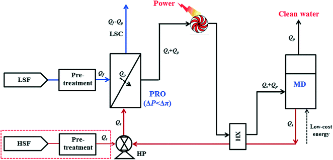
Fig. 1 shows the schematic of the proposed PRO–MD hybrid process for osmotic power and clean water generation. In a typical operation, the pretreated seawater or synthetic NaCl solution termed as high salinity feed (HSF, Qs) is firstly pressurized by a high-pressure pump (HP) and then enters the PRO subsystem as the draw solution. Simultaneously, a pretreated low salinity feed (LSF, Qf) such as freshwater or wastewater is used as the feed in the PRO subsystem. Since the hydraulic pressure difference is smaller than the osmotic pressure gradient between these two solutions (ΔP < Δπ), the pressurized draw solution spontaneously extracts water (Qp) from the feed under isobaric conditions (ΔP) through forward osmosis, resulting in a low salinity concentrate (LSC) with a much reduced volume (Qf − Qp) and a diluted draw solution with an expanded volume (Qs + Qp). After exiting the PRO unit, the sum (Qs + Qp) is utilized to drive the energy generation device such as a hydro turbine for electric power generation. Then, the depressurized and diluted draw solution (Qs + Qp) enters the MD subsystem as the feed. Driven by solar energy or other low-grade heat sources, high quality clean water (Qp) is produced while a concentrated brine (Qs) is simultaneously regenerated. The concentrated brine (Qs) that left the MD subsystem is firstly heat exchanged with the diluted draw solution (Qs + Qp) using a heat exchanger (HX) to further increase the energy savings of the hybrid system and then circulated back to the PRO subsystem as the draw solution. Since MD can desalinate feed waters with higher TDS concentrations (close to its saturation point), a great salinity draw solution can be generated for a sustainable PRO operation. On the other hand, the concentrated feed (Qf − Qp) from PRO could be discharged or reused depending on the water salinity and purity.The PRO–MD hybrid process not only can avoid the shortcomings of each subsystem but also strengthen their advantages. Compared to a standard MD process, the net energy consumption for desalination is lowered by the power generated from PRO, while the fouling is negligible since the circulated draw solution is almost free of foulants which reduces the membrane replenishment costs. From the perspective of PRO, the draw solution is an abundantly available and low-cost residual from the MD subsystem but with high purity and salinity. Therefore, ultrahigh osmotic energy is achievable and the membrane fouling on the draw solution side of the PRO membrane could be highly controlled. Since the PRO subsystem is able to achieve a high water recovery rate through forward osmosis, the feed water stream could be effectively concentrated and its discharge volume would be much reduced. In addition, the closed loop mitigates the disposal problems of the MD concentrated brine and the resultant brackish water from the PRO processes. Furthermore, the elimination of the chemical usage in conventional pretreatment steps and the reuse of impaired wastewater make this integrated process more environmentally friendly. Nevertheless, one possible drawback of the PRO–MD hybrid process might be the relatively high energy consumption in the MD subsystem unless low-grade heat and other renewable energy such as solar power are used. Salts from the circulated draw solution may get lost in the PRO subsystem due to reverse salt diffusion (reverse salt flux); however, this problem can be minimized by using effective PRO membranes with excellent salt rejections.
The main operation variables for the PRO–MD hybrid process include (1) the salinity and quality of the feed water and draw solution, (2) membrane power density and its salt rejection, (3) water recovery rate of the feed and the dilution effects of the draw solution (or the degree of mixing) in the PRO subsystem, (4) water flux and salt rejection in the MD subsystem, and (5) the fouling and scaling behaviours of each subsystem. These parameters are correlated with one another and should be optimized over a wide operational range to ensure an effective operation of the hybrid system.
2.2 The PRO subsystem for osmotic power generation
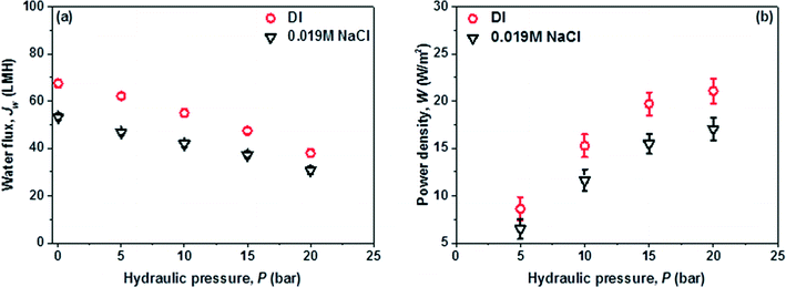
A lab-scale counter-current flow PRO subsystem with a high pressure pump was used for power generation. Synthetic seawater with a NaCl concentration of 0.6 M was utilized as the initial draw solution which was reconcentrated by the MD subsystem to different salinities (i.e. 0.8 M and 2 M) and then circulated back to PRO as the new draw solution. In order to assess the maximum potential for power generation of the PRO–MD process, deionized (DI) water and synthetic brackish water (0.019 M NaCl) were firstly used as the feeds in the PRO subsystem to exclude the fouling issues. After that, wastewater brine (WWBr) from NEWater treatment plants was employed to mimic the real practical applications of the hybrid process. In Singapore, the NEWater plants receive municipal wastewater and treat it with a three-stage process including microfiltration (MF), low pressure reverse osmosis (RO) and ultraviolet (UV) disinfection. The resultant wastewater brine from the low pressure RO has a salinity close to that of river water (i.e., 0.019 M NaCl solution with an osmotic pressure of around 0.5 bar).19,27 Due to the limited membrane surface area of the PRO module, the water streams were circulated during the tests. The draw solution and feed velocities are 0.5 m s−1 and 0.15 m s−1, respectively. The detailed PRO setup (Fig. S1†), operation conditions, and the determination of water permeation flux, reverse salt flux and power density can be found in the ESI.†A high performance PES-TFC hollow fiber membrane with balanced transport properties and robust strength was prepared and used in the PRO subsystem for power generation. In terms of water permeation flux, salt rejection and power density, this PES-TFC membrane is one of the state-of-the-art PRO membranes.11,14,28 The membrane morphology is shown in Fig. 1, while its transport properties, structural parameter, fiber dimension and burst pressure are tabulated in Table 1. The details of membrane fabrication and characterization are presented in the ESI† and in our previous work.19
| Membrane | Water permeability, A (L m−2 h−1 bar−1) | Salt rejection, R (%) (2000 ppm @ 5 bar) | Salt permeability, B (L m−2 h−1) | S (μm) | OD/ID (μm) | Burst pressure (bar) |
|---|---|---|---|---|---|---|
| PES-TFC | 3.3 ± 0.3 | 97.5 ± 0.2 | 0.31 ± 0.3 | 450 | 973/562 | >20.0 |
2.3. The MD subsystem for clean water production
One lab-scale vacuum membrane distillation (VMD) system was employed in the PRO–MD hybrid process to produce clean water via desalination and regenerate the diluted PRO draw solution. Compared to other MD configurations, VMD possesses the advantages of higher permeation flux and better thermal efficiency.22,29–31 The detailed experimental apparatus is depicted in the ESI (Fig. S2†). A lab-fabricated poly(vinylidene fluoride) (PVDF) flat-sheet membrane was employed for the MD subsystem. The descriptions of membrane fabrication and characterization methods are listed in the ESI,† and the membrane specifications are tabulated in Table 2. Three feed temperatures, namely 40, 50 and 60 °C, were used for MD and the water flux and solute rejection of the PVDF membrane at each temperature were studied.| Membrane | Mean pore size (nm) | Water contact angle (°) | Porosity (%) | Selective layer | Effective area per module (cm2) |
|---|---|---|---|---|---|
| PVDF | 168.4 ± 1.6 | 86.3 ± 1.3 | 78.6 ± 2.3 | Top surface | 15.2 |
3. Results and discussion
3.1 Characteristics of the PES-TFC PRO membrane and the PVDF MD membrane
Fig. 2(a–c) show the membrane morphology of the TFC PRO hollow fiber membrane. It consists of a thin polyamide selective layer on the inner surface of a porous polyethersulfone (PES) fiber substrate. Macroscopically, the PES-TFC membrane possesses good concentricity and a medium dimension in diameter (i.e. OD is 973 μm) with a relatively thick cross-section of 205 μm (Table 1). Microscopically, this membrane has a straight finger-like macrovoid structure near the inner cross-section and a highly porous open-cell micro-structure in the outer surface which is capable of reducing water transport resistance.32,33 Therefore, this PES-TFC membrane not only possesses outstanding robust strength but also exhibits promising transport characteristics. As shown in Table 1, it has a high water permeability, A, of 3.3 L m−2 bar−1 h−1 accompanied by a low salt permeability, B, of 0.31 L m−2 h−1. Most importantly, it also has a small structural parameter, S, of 450 μm, suggesting that the detrimental effects of internal concentration polarization (ICP) could be significantly reduced.14 Furthermore, this membrane exhibits a high burst pressure of larger than 20 bar, which enables the PRO operation at a large hydraulic pressure when a high salinity draw solution is used.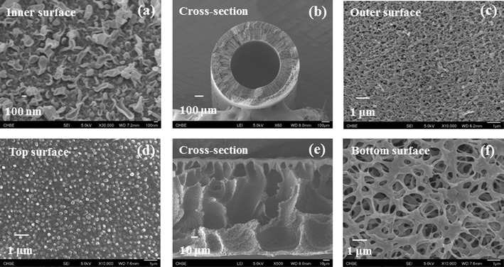 | ||
| Fig. 2 The surface and cross-section morphology of the PES-TFC PRO hollow fiber membrane (a–c), and the PVDF MD flat-sheet membrane (d–f). | ||
The basic osmotic performance (when ΔP = 0) of the PES-TFC hollow fiber membrane as a function of draw solution salinity under the PRO mode was firstly evaluated using deionized water as the feed and NaCl solutions with different concentrations as draw solutions. As depicted in Fig. 3, the PES-TFC membrane shows a high volumetric water flux, Jw, of 54.6 L m−2 h−1 (abbreviated as LMH) using 0.6 M NaCl as the draw solution. When the draw solution concentration is raised to 0.8 M and 2.0 M, significant increases in Jw of 67.5 L m−2 h−1 and 87.3 L m−2 h−1 are achieved, respectively. At the same time, this membrane displays quite low reverse salt fluxes, Js, of less than 13.5 g m−2 h−1 even for the 2.0 M draw solution, indicating that the salt loss in the PRO subsystem could be well controlled. Clearly, this PES-TFC hollow fiber membrane is an effective PRO membrane that could facilitate a high efficiency power generation in the PRO–MD hybrid process because of its remarkably high Jw, low Js, small S, and outstanding membrane robustness.
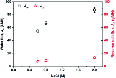 | ||
| Fig. 3 Water flux, Jw, and reverse salt flux, Js, of the PES-TFC PRO membrane as a function of draw solution concentration at ΔP = 0 bar. The feed is deionized water. | ||
Fig. 2(d–f) show the FESEM images of the PVDF flat-sheet membrane for the MD subsystem. By manipulating dope formulation and coagulation conditions,34,35 the PVDF membrane possesses a thin layer of relatively dense top surface, an open-pore bottom surface, and a porous cross-section full of macrovoids. The thin top surface layer provides the separation, while the porous cross-section not only offers a low transport resistance but also reduces the thermal conductivity across the membrane because it has a large porosity up to 78% (Table 2). The porous bottom surface provides uninterrupted transport channels for water transport. Since the PVDF membrane has a relatively small mean pore size of 168 nm, it helps maintain the vacuum of the membrane module at the permeate side and provides better wetting resistance. Besides, the MD membrane is relatively hydrophobic with a water contact angle of 86.3° ± 1.3 (Table 2) due to the hydrophobic nature of the PVDF material and the membrane surface morphology.
3.2 The MD subsystem for clean water production and draw solution regeneration
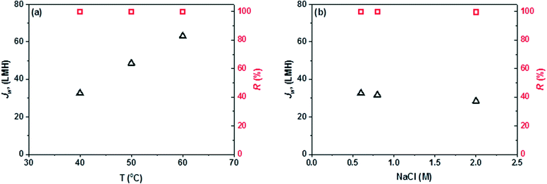
The MD subsystem has two functions in the PRO–MD hybrid system; namely, produce clean water and simultaneously regenerate the PRO draw solution with a high salinity. Fig. 4(a) displays the clean water production rate (Jw) and salt rejection (R) versus feed inlet temperature by using a 0.6 M NaCl solution as the feed. Due to the exponentially-improved water vapor pressures at higher temperatures, there is a significant increase in water flux with increasing feed temperature.36 A high Jw of 63.1 L m−2 h−1 is obtained at a relatively low feed temperature of 60 °C, which surpasses most MD membranes reported in the literature because of the specifically-designed membrane structure and morphology.23,25,31,32The other task of the MD subsystem is to regenerate a high salinity draw solution for the PRO subsystem. Fig. 4(b) shows the MD desalination performance as a function of feed salinity at a fixed feed temperature of 40 °C. A slight decline in Jw is observed with increasing feed salt concentration. This is due to the fact that a higher salt concentration would induce a larger reduction in water partial vapor pressure and thus lower the driving force. In addition, the viscosity increase in a highly concentrated feed may decrease the mass transfer rate.37,38 However, it is worth noting that the Jw in the MD subsystem is not significantly influenced by the feed salt concentration or feed water recovery rate. This is an important advantage for the PRO–MD hybrid system since highly concentrated NaCl solutions could be generated as ideal draw solutions for the PRO subsystem for power generation. In addition, the conductivities of all produced waters are smaller than 5 μS cm−1, which correspond to a salt rejection greater than 99.9% (Fig. 4). This suggests that high quality clean water can be produced and the salt loss in the MD subsystem is negligible. Membrane fouling is not significantly observed in MD because the recycled solution is almost free of foulants and the salt concentration is far from the saturation point. Overall, MD is a promising subsystem for the hybrid process which not only can produce clean water with a high water recovery, but also regenerate an effective PRO draw solution with a high salinity.
3.3 The PRO subsystem for osmotic power generation
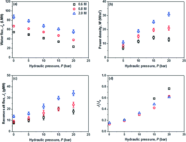
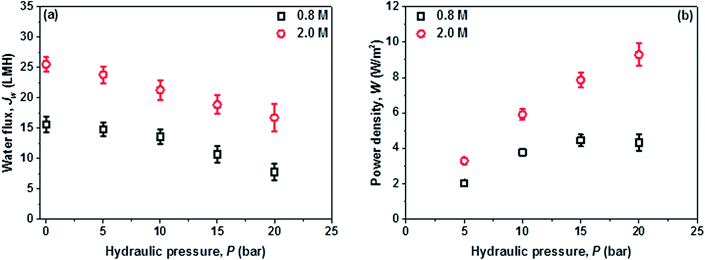
In the PRO subsystem, membrane power density, W, is an important performance indicator which is directly determined by the water permeation flux, Jw, and the trans-membrane pressure difference ΔP. Jw is not only affected by the characteristics of the PRO membrane such as A, B and S, but also is closely related to the salinity (i.e. Δπ) and quality (i.e. fouling) of the feed and draw solutions. Ideally, the optimal ΔP for the peak power density is equal to Δπ/2; however, this ΔP can be quite high when a high Δπ is applied and is currently restricted by the low strength of the PRO membranes. The feed water recovery rate, Re (Qp/Qf), reverse salt flux, Js, and specific reverse salt flux, Js/Jw, are also the key factors because Re determines the overall water and energy output of the hybrid system, the dilution of draw solution and the feed volume reduction (Qf − Qp), while Js and Js/Jw control the loss of the circulated draw solute that is closely related to ICP and the effective Δπ across the PRO membrane.Since W is a product of Jw and ΔP, W increases with ΔP until it reaches the peak value. In this study, extremely high W of 14.3 W m−2 and 31.0 W m−2 are obtained by using the 0.6 M draw solution at around 15 bar and the 2.0 M draw solution at 20 bar, respectively. To the best of our knowledge, the currently achieved Jw and W surpass those of other PRO systems reported in the literature.10,28,39,40 A much larger W could be projected at higher pressures for the 2 M draw solution if a stronger PRO membrane is available. In addition, the PRO subsystem can harvest a W of about 10 W m−2 even at a low ΔP of 5 bar when using a high salinity draw solution of 2 M NaCl, suggesting the great process flexibility of the newly developed hybrid system. As displayed in Fig. 4, the MD performance is mainly controlled by the operating temperature and is almost not affected by the feed water salinity. If waste heat or solar energy is used for the MD subsystem, a highly concentrated draw solution could be generated for the PRO subsystem and the power output will be much higher than that of a typical river-to-sea PRO osmotic power plant.6,8,21,41
The reverse salt diffusion across the PRO membrane from the draw solution into feed does occur. However, a large Js or Js/Jw is unacceptable because it will directly reduce the membrane performance and lower the PRO efficiency.42,43 Therefore, in addition to Jw and W, Js and Js/Jw are important parameters for the PRO subsystem. As displayed in Fig. 5(c) and (d), the PES-TFC membrane shows a relatively low Js of 7.8–13.5 g m−2 h−1 (abbreviated as gMH) at 0 bar using 0.6–2.0 M NaCl as draw solutions. The increments in Js with increasing ΔP and draw solution concentration are observed but not significant, whereby Js slightly increases to 17.9–34.3 g m−2 h−1 at 20 bar. The Js/Jw ratio characterizes the mass of reverse draw solute per unit volume of permeate water. Due to the high selectivity and good mechanical strength of the PES-TFC membrane, a low Js/Jw of less than 0.76 g L−1 is achieved even at high pressures when using highly concentrated draw solutions. PRO membranes with a higher selectivity would further minimize the negative effects of reverse salt fluxes.
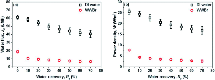
Fig. 7 further displays the PRO performance when real wastewater brine (WWBr) is used as the feed for practical applications. Jw drops dramatically to 15.6 L m−2 h−1 at 0 bar when using 0.8 M NaCl as the draw solution and to 7.8 L m−2 h−1 when ΔP is raised to 20 bar, resulting in a much lower peak W of 4.3 W m−2. Compared to the results of Fig. 6, these reductions are mainly attributed to the membrane fouling and scaling where the inorganic salts and organic foulants accumulate on the membrane outer surface and/or penetrate into the porous substrate during water permeation across the membrane.44–47 The WWBr is the retentate of a low pressure RO and its composition is more complicated compared to freshwater and the synthetic brackish water (Table S1†),19 although it possesses a salinity close to 0.0119 M NaCl. However, the negative effects of membrane fouling could be partially counteracted by using high salinity draw solutions in the newly developed PRO–MD process. As shown in Fig. 7, W at 20 bar could be significantly increased to 9.3 W m−2 when using a 2 M MD concentrate as the draw solution. The achieved W is higher than the estimated threshold of 5 W m−2 that would make PRO economically feasible.7,10 Clearly, the newly developed PRO–MD hybrid system is promising not only in harvesting osmotic energy from freshwater but also from wastewater.
4. Consideration and perspectives of the PRO–MD process
A hybrid pressure retarded osmosis–membrane distillation (PRO–MD) process has been conceptually demonstrated for osmotic power generation and clean water production from various waters. The proposed PRO–MD system is promising and can harvest osmotic energy either from freshwater or wastewater. Advantages of the integrated PRO–MD process include, but not limited to, high water recovery rate, huge osmotic power generation, well-controlled membrane fouling, and minimal environmental impacts. Particularly, when using a 2 M NaCl MD concentrate as the draw solution, ultrahigh power densities of 31.0 W m−2 and 9.3 W m−2 have been harvested by the PRO subsystem using deionized water and real wastewater brine as the feeds, respectively.To further maximize the potential of the proposed PRO–MD process for osmotic power and clean water production, future research studies must further improve the performance of the membranes and reduce the reverse salt flux in the PRO subsystem. This can be achieved by designing highly selective PRO membranes with a minimal salt permeability and/or employing a novel draw solute that possesses a large molecule size and negligible leakage. In addition, fouling occurs fast on the feed water side of the PRO membrane when real wastewater is used as feed. There is a critical need to fabricate effective anti-fouling PRO membranes and explore effective fouling mitigation methods. The energy consumption in the MD desalination subsystem may be relatively high (i.e., $1.0–1.4 m−3);48 however, it can be reduced by applying a heat exchanger in the hybrid system and employing low-grade heat or solar power for heating up the feed solution.
Acknowledgements
This research was funded under the project entitled “Membrane development for osmotic power generation, part 1. Materials development and membrane fabrication” (1102-IRIS-11-01) and the NUS grant no. of R-279-000-381-279. This research grant is supported by the Singapore National Research Foundation under its Environmental & Water Technologies Strategic Research Programme and administered by the Environment & Water Industry Programme Office (EWI) of the PUB.References
- N. Ghaffour, S. Lattemann, T. Missimer, K. C. Ng, S. Sinha and G. L. Amy, Appl. Energy, 2014, 136, 1155–1165 CrossRef CAS PubMed.
- B. E. Logan and M. Elimelech, Nature, 2012, 488, 313–319 CrossRef CAS PubMed.
- S. Loeb, Science, 1975, 189, 654–655 CAS.
- K. Gerstandt, K. V. Peinemann, S. E. Skilhagen, T. Thorsen and T. Holt, Desalination, 2008, 224, 64–70 CrossRef CAS PubMed.
- K. L. Lee, R. W. Baker and H. K. Lonsdale, J. Membr. Sci., 1981, 8, 141–171 CrossRef CAS.
- G. Z. Ramon, B. J. Feinberg and E. M. V. Hoek, Energy Environ. Sci., 2011, 4, 4423–4434 CAS.
- T. Thorsen and T. Holt, J. Membr. Sci., 2009, 335, 103–110 CrossRef CAS PubMed.
- T. S. Chung, X. Li, R. C. Ong, Q. Ge, H. Wang and G. Han, Curr. Opin. Chem. Eng., 2012, 1, 246–257 CrossRef CAS PubMed.
- J. Kim, J. Lee and J. H. Kim, Desalin. Water Treat., 2012, 43, 193–200 CrossRef CAS PubMed.
- A. Achilli, J. L. Prante, N. T. Hancock, E. B. Maxwell and A. E. Childress, Environ. Sci. Technol., 2014, 48, 6437–6443 CrossRef CAS PubMed.
- G. Han, S. Zhang, X. Li and T. S. Chung, Prog. Polym. Sci., 2015 DOI:10.1016/j.progpolymsci.2015.04.005.
- G. Han, S. Zhang, X. Li and T. S. Chung, J. Membr. Sci., 2013, 440, 108–121 CrossRef CAS PubMed.
- G. Han, P. Wang and T. S. Chung, Environ. Sci. Technol., 2013, 47, 8070–8077 CrossRef CAS PubMed.
- S. Zhang and T. S. Chung, Environ. Sci. Technol., 2013, 47, 10085–10092 CrossRef CAS PubMed.
- N. Bui and J. R. McCutcheon, Environ. Sci. Technol., 2013, 47, 1761–1769 CAS.
- S. Chou, R. Wang and A. G. Fane, J. Membr. Sci., 2013, 448, 44–54 CrossRef CAS PubMed.
- S. P. Sun and T. S. Chung, Environ. Sci. Technol., 2013, 47, 13167–13174 CrossRef CAS PubMed.
- A. Efraty, Desalin. Water Treat., 2013, 51, 7420–7430 CrossRef CAS PubMed.
- C. F. Wan and T. S. Chung, J. Membr. Sci., 2015, 479, 148–158 CrossRef CAS PubMed.
- S. Lin, A. P. Straub and M. Elimelech, Energy Environ. Sci., 2014, 7, 2706–2714 CAS.
- S. K. Sikdar, Clean Technol. Environ. Policy, 2014, 16, 1481–1485 CrossRef PubMed.
- E. Curcio and E. Drioli, Sep. Purif. Rev., 2005, 34, 35–86 CrossRef CAS.
- F. Edwie and T. S. Chung, Chem. Eng. Sci., 2013, 98, 160–172 CrossRef CAS PubMed.
- M. Gryta, M. Tomaszewska, J. Grzechulska and A. W. Morawski, J. Membr. Sci., 2001, 181, 279–287 CrossRef CAS.
- L. Francis, N. Ghaffour, A. Al-Saadi, S. P. Nunes and G. L. Amy, J. Membr. Sci., 2014, 455, 103–112 CrossRef CAS PubMed.
- J. G. Lee, Y. D. Kim, S. M. Shim, B. G. Im and W. S. Kim, Desalination, 2015, 363, 82–91 CrossRef CAS PubMed.
- J. J. Qin, O. M. Htun, W. M. Nyunt, H. Lee, S. P. Hong, J. E. Kim, Y. Xing and M. Zhanga, Desalination, 2005, 171, 299–305 CrossRef CAS PubMed.
- C. Klaysom, T. Y. Cath, T. Depuydt and I. F. J. Vankelecom, Chem. Soc. Rev., 2013, 42, 6959–6989 RSC.
- K. W. Lawson and D. R. Lyoyd, J. Membr. Sci., 1997, 124, 1–25 CrossRef CAS.
- L. Francis, N. Ghaffour, A. S. Al-Saadi, S. P. Nunes and G. L. Amy, J. Membr. Sci., 2014, 49, 2045–2053 CAS.
- A. Alsaadi, L. Francis, H. Maab, G. L. Amy and N. Ghaffour, J. Membr. Sci., 2014, 471, 138–148 CrossRef CAS PubMed.
- G. Han, T. S. Chung, M. Toriida and S. Tamai, J. Membr. Sci., 2012, 423–424, 543–555 CrossRef CAS PubMed.
- J. R. McCutcheon and M. Elimelech, AIChE J., 2007, 53, 1736–1744 CrossRef CAS PubMed.
- E. Fontananova, J. C. Jansen, A. Cristiano, E. Curcio and E. Drioli, Desalination, 2006, 192, 190–197 CrossRef CAS PubMed.
- M. Gryta and M. Tomaszewska, J. Membr. Sci., 1998, 144, 211–222 CrossRef CAS.
- S. Bonyadi and T. S. Chung, J. Membr. Sci., 2007, 306, 134–146 CrossRef CAS PubMed.
- F. Edwie and T. S. Chung, J. Membr. Sci., 2012, 421–422, 111–123 CrossRef CAS PubMed.
- R. W. Schofield, A. G. Fane, C. J. D. Fell and R. Macoun, Desalination, 1990, 77, 279–294 CrossRef CAS.
- I. L. Alsvik and M. B. Hägg, Polymers, 2013, 5, 303–327 CrossRef PubMed.
- A. Altaee and A. Sharif, Desalination, 2015, 356, 31–46 CrossRef CAS PubMed.
- N. Y. Yip and M. Elimelech, Environ. Sci. Technol., 2012, 46, 5230–5239 CrossRef CAS PubMed.
- G. Han, Q. Ge and T. S. Chung, Appl. Energy, 2014, 132, 383–393 CrossRef CAS PubMed.
- L. Huang, N. N. Bui, M. T. Meyering, T. J. Hamlin and J. R. McCutcheon, J. Membr. Sci., 2013, 437, 141–149 CrossRef CAS PubMed.
- Q. She, X. Jin, Q. Li and C. Y. Tang, Water Res., 2012, 46, 2478–2486 CrossRef CAS PubMed.
- Y. Liu and B. Mi, J. Membr. Sci., 2014, 450, 153–161 CrossRef CAS PubMed.
- Q. She, Y. K. W. Wong, S. Zhao and C. Y. Tang, J. Membr. Sci., 2013, 428, 181–189 CrossRef CAS PubMed.
- S. C. Chen, C. F. Wan and T. S. Chung, J. Membr. Sci., 2015, 479, 190–203 CrossRef CAS PubMed.
- S. A. Obaidani, E. Curcio, F. Macedonio, G. D. Profio, H. A. Hinai and E. Drioli, J. Membr. Sci., 2008, 323, 85–98 CrossRef PubMed.
Footnote |
| † Electronic supplementary information (ESI) available: Materials and membrane characterization methods; wastewater brine (WWBr) composition (Table S1); PES hollow fiber spinning and post-treatment; fabrication of PES-TFC PRO membrane via interfacial polymerization; PVDF membrane fabrication; PRO process and subsystem (Fig. S1); PRO performance tests and evaluation; VMD process and subsystem (Fig. S2); and MD performance tests. See DOI: 10.1039/c5ew00127g |
| This journal is © The Royal Society of Chemistry 2015 |

