
Microbial capacitive desalination for integrated organic matter and salt removal and energy production from unconventional natural gas produced water†
Casey
Forrestal
a,
Zachary
Stoll
b,
Pei
Xu
*b and
Zhiyong Jason
Ren
*a
aDepartment of Civil, Environmental, and Architectural Engineering, University of Colorado Boulder, Boulder, CO 80309, USA. E-mail: jason.ren@colorado.edu; Fax: +1(303) 492-7317; Tel: +1(303) 492–4137
bDepartment of Civil Engineering, New Mexico State University, Las Cruces, NM 88003, USA. E-mail: pxu@nmsu.edu; Tel: +1(575) 646-5870
First published on 5th November 2014
Abstract
The rapid development of unconventional oil and gas generates a large amount of contaminated produced water. The treatment and reuse of such water generally require multiple treatment processes to remove different constituents from the waste, such as salts and organic matter. This study characterized the performance of a new microbial capacitive desalination technology for simultaneous removal of organic pollutants and salts from shale gas produced water as well as its energy production during the process. The microbial capacitive desalination cell (MCDC) was able to remove total dissolved solids (TDS) at a rate of 2760 mg of TDS per liter per hour and chemical oxygen demand (COD) at a combined rate of 170 mg of COD per liter per hour, which was 18 times and 5 times faster than the traditional microbial desalination cell (MDC), respectively. The MCDC had a coulombic efficiency of 21.3%, and during capacitive deionization regeneration, 1789 mJ g−1 activated carbon cloth (ACC) was harvested. One advantage of MCDC is that all three chambers could be used to remove both organic and inorganic contaminants. The reactor removed greater than 65% of the TDS and 85% of the COD in 4 hours of operation in the desalination chamber, and more than 98% of the salts and 75% of the organics were recovered during the regeneration process. This technology provides a new integrated process to complement current systems for organic matter and salt removal as well as energy recovery from real produced water.
Water impactThe natural gas boom through hydraulic fracking generates a tremendous amount of wastewater containing high salinity and organic carbon but without an efficient and sustainable treatment method. Much of such produced water being generated is in remote locations with limited access to water and energy, which drives up treatment cost and promotes technologies with water reuse and energy generation capabilities. The microbial capacitive desalination system produces energy and simplifies the treatment process through the integration of organic and salinity removal, which makes field point-of-source treatment a more viable option. |
Introduction
Produced water generated during oil and gas exploration and production is a significant environmental impediment to the energy industry. In the United States, the total produced water volume was estimated to be at 21 billion barrels per year, and its disposal costs an estimated $5 billion dollars.1 The produced water volume significantly increased in recent years due to the dramatic expansion of natural gas production from unconventional sources such as shale gas, coalbed methane, and tight sand.2 Natural gas is a low-cost and cleaner fuel source as compared to coal, but the production of unconventional gas using hydraulic fracturing requires a significant amount of water and produces a large amount of wastewater.3–5Handling, treatment, disposal, and beneficial reuse of produced water have been great challenges for the industry and regulators.6,7 Produced water quality from different sites varies significantly, and the water generally contains multiple pollutants that cannot be discharged and reused directly.8,9 Both hydraulic fracturing flowback water and produced water contain a wide range of hydrocarbons, salts, chemical additives, sands, and occasionally naturally occurring radioactive materials.5 The quality of produced water is highly variable depending on the geochemistry of the formation, with total dissolved solids (TDS) ranging from 8000 mg L−1 (Greater Green River) to 180![[thin space (1/6-em)]](https://www.rsc.org/images/entities/char_2009.gif) 000 mg L−1 (Marcellus Shale) and total organic carbon (TOC) ranging up to 2000 mg L−1.10 Currently, underground injection is the primary disposal method for onshore wells to maintain formation pressure and minimize disposal cost.1 Due to shortages of water resources and the safety and health concerns associated with underground injection, treatment and reuse of produced water have become emerging needs. However, the transportation of a large volume of water to existing wastewater treatment facilities is prohibitive in many areas because the associated traffic and cost are very high, and the high salinity and hydrocarbon content in such water may negatively affect the performance of traditional treatment processes.11 For onsite produced water treatment, multiple technologies are often combined to target removal of different constituents. For example, an air flocculation separator is in general the first step, which removes and recovers suspended oil. Then, separate processes such as biological treatment and membrane processes are connected to remove organic contents and salts, respectively. Popular desalination technologies such as thermal evaporation and reverse osmosis (RO) can be effective in salt removal but at very high operation and energy cost. New membrane-based technologies such as forward osmosis and reverse electrodialysis are currently being investigated as pretreatment options for RO to lower the required energy demand.12 However, most membrane technologies are ineffective in organic hydrocarbon removal and require extensive pre-treatment to protect system components.13,14
000 mg L−1 (Marcellus Shale) and total organic carbon (TOC) ranging up to 2000 mg L−1.10 Currently, underground injection is the primary disposal method for onshore wells to maintain formation pressure and minimize disposal cost.1 Due to shortages of water resources and the safety and health concerns associated with underground injection, treatment and reuse of produced water have become emerging needs. However, the transportation of a large volume of water to existing wastewater treatment facilities is prohibitive in many areas because the associated traffic and cost are very high, and the high salinity and hydrocarbon content in such water may negatively affect the performance of traditional treatment processes.11 For onsite produced water treatment, multiple technologies are often combined to target removal of different constituents. For example, an air flocculation separator is in general the first step, which removes and recovers suspended oil. Then, separate processes such as biological treatment and membrane processes are connected to remove organic contents and salts, respectively. Popular desalination technologies such as thermal evaporation and reverse osmosis (RO) can be effective in salt removal but at very high operation and energy cost. New membrane-based technologies such as forward osmosis and reverse electrodialysis are currently being investigated as pretreatment options for RO to lower the required energy demand.12 However, most membrane technologies are ineffective in organic hydrocarbon removal and require extensive pre-treatment to protect system components.13,14
One approach to accomplish sustainable produced water management is to develop technologies that remove both organic contaminants and salts without external energy consumption or potential net energy gain. In this context, recently developed microbial desalination systems (MDS) may provide a niche in the market.15 MDS is based on the fundamental work on bioelectrochemical systems (BES), which employ microorganisms to breakdown organic or inorganic sources of electrons and transfer those electrons to a terminal electron acceptor such as oxygen through a pair of electrodes. The internal potential generated between the anode and the cathode drives additional salt removal, and the energy can be harvested for electricity and chemical production.16–18 Different reactor configurations have been reported, such as a microbial desalination cell (MDC), in which three chambers were separated by a pair of ion exchange membranes and salt removal was accomplished by migrating ions from the middle chamber to the anode and cathode chambers.19–23
This study used a newly developed microbial capacitive desalination cell (MCDC) to demonstrate its efficacy in removing both organic contaminants and salts from produced water collected from a shale gas field and its energy recovery during the operation.24,25 MCDC alleviates salt migration problems associated with MDC through the integration with capacitive deionization (CDI). CDI is a desalination method where an electrical potential is applied to high surface area electrodes to adsorb charged organic and inorganic species for desalination.24 CDI is a dynamic process of salt removal and recovery.26 When the electrical potential is removed, the capacitively desalinated salts can be removed and captured for beneficial use, and part of the electrical charge can be recovered.16,24,25,25,27,28 CDI only requires a small voltage (<1.4 V) to form the electric double layer, so it can be externally powered by an MFC.28,29 Previous studies showed that such an MFC–CDI system could achieve a desalination rate of 35.6 mg of TDS per liter per hour, with a desorption rate up to 200.6 mg of TDS per liter per hour.27 The MCDC system consists of three chambers, the anode, cathode and middle chambers which contain the electrodes for CDI. The use of microbial-generated energy applied to CDI electrodes allows for an energy-positive desalination system. A reactor with integrated capacitive electrodes has also been studied for energy harvesting from the entropic energy released from mixing salt water and freshwater, called capacitive mixing.29 This study also compared the performance with traditional MDC reactors. Compared to previous studies that employed multistage treatment processes for organic matter and salt removal, this study introduces a new and simple approach for energy-positive produced water management, and it is one of the few studies that used real produced water samples instead of artificial mixtures. It is also the first attempt at using the same raw feed water in all three chambers of the reactors, which greatly simplified the operation and brings the technology one step further toward application.
Materials and methods
Produced water characteristics and reactor design
The produced water samples were collected from a wastewater treatment plant (WWTP) in Piceance Basin, Colorado, which receives wastewater during shale gas exploration and production. The water samples were pretreated in the WWTP to partially remove solid, oil, and volatile compounds through hydrocyclones, dissolved air flotation, and air stripping. Table S1 in the ESI† lists the main characteristics of the produced water, which was used as the sole influent for the reactors in this study. The total dissolved solid (TDS) concentration was 15870 ± 290 mg L−1, the COD concentration ranged 800–1100 mg L−1, and the pH value ranged from 7.4 to 7.8. The major ions detected in the produced water include chloride, alkali, calcium, magnesium and sodium, and the relative abundance of these ions is consistent with the literature on produced water.5–8 Two experimental procedures were designed and operated for produced water treatment and energy production. The first was a comparison study between the MCDC using capacitive deionization and the MDC technology using electrodialysis for desalination. The second only investigated the MCDC maximum desalination rate, operating under advanced desalination methods with a regeneration method similar to capacitive mixing.
The MCDC reactor consisted of three cubic polycarbonate blocks with a 3 cm diameter hole forming an internal anode chamber, a desalination chamber, and a cathode chamber with volumes of 23, 12, and 27 mL, respectively (Fig. 1).24,30 The anode and cathode chambers were 4 cm in length and the desalination chamber had a length of 1.5 cm. Carbon brush (Golden Brush, CA) was used as the anode electrode, and traditional air cathodes were made by applying 0.5 mg cm−1 Pt/C and four PTFE diffusion layers on 30% wet-proofed carbon cloth.21,31 Two cation exchange membranes (Astom Corporation, Japan) were used to separate the three chambers. The use of two cation exchange membranes allows for cations to freely move throughout the entire reactor.24 Inside the desalination chamber, a capacitive deionization (CDI) module consisted of two activated carbon cloths (ACC) (with a BET surface area of 1019.8 m2 g−1, a thickness of 0.7 mm, and a 40% w/w ethyl acetate uptake) electrode assemblies, which were connected to the anode and cathode, respectively. Each assembly was split into three parts and placed overlapping. Plastic mesh was used to prevent short circuiting between the electrodes. Spacing between the electrodes was 2.1 mm. A total of 0.72 g of ACC was used for the CDI module. Ni/Cu was used as a current collector (McMaster-Carr) for ACCs. The MDC reactor had the same reactor dimensions and used the same anode and cathode materials as those of MCDC, except that an anion exchange membrane (AEM) (Astom Corporation, Japan) was placed between the anode and the desalination chambers and a CEM was placed between the desalination and the cathode chambers. No CDI modules were integrated with MDC, and a 1000 Ω resistor was placed between the anode and the cathode.
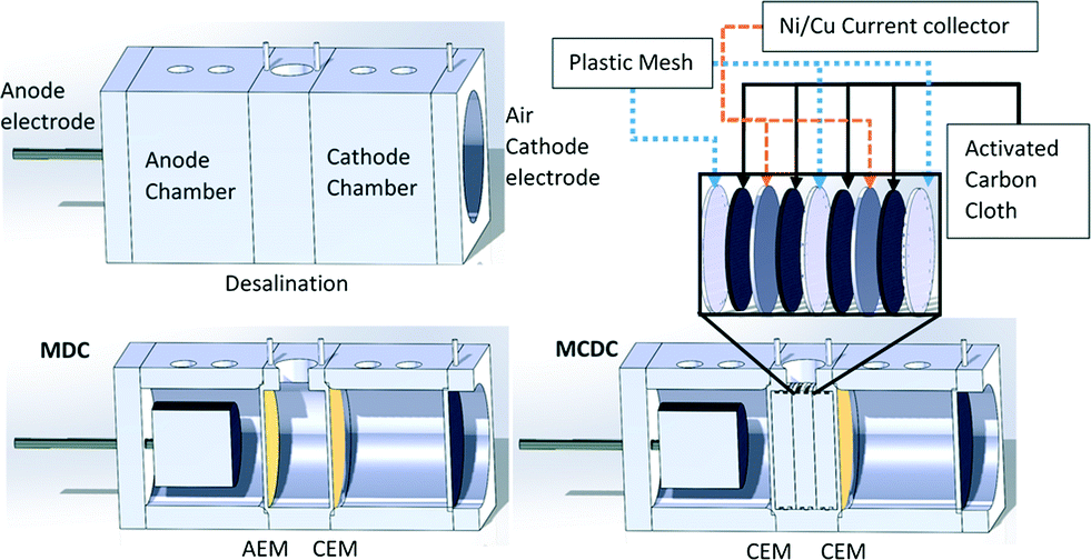 | ||
| Fig. 1 Configuration of the MDC (left) and MCDC (right) systems. The image represents the investigated small cube systems. The cut-out of the MDC shows where the anion exchange membrane and cation exchange membrane are located compared to that of the MCDC system with a blow-up of the capacitive deionization module in the middle chamber. | ||
Reactor operation and controls
Both MCDC and MDC reactors were initially operated in microbial fuel cell mode by removing the middle chamber and inoculating the anode chamber with activated sludge. Inoculation was only required initially for anode biofilm acclimation. When a repeatable voltage profile (>500 mV) was observed for three consecutive cycles, which suggests stable microbial activity, the reactors were shifted to desalination mode by partially disassembling the reactors and quickly inserting the membranes and the middle chamber as described previously.20,32 The anolyte was transitioned from 10 mM sodium acetate-buffered medium to 100% produced water. In the comparative study, only a 200 mM phosphate buffer solution was used as the catholyte (pH 7.0 ± 0.1), and produced water was used in the desalination chamber. Each of the three chambers was connected to a separate 100 mL reservoir, and water was continuously recirculated at a rate of 2 mL min−1 between each chamber and reservoir.15 The MCDC desalination chamber was first recirculated with produced water to ensure saturated physical adsorption. Full physical adsorption was determined when the change in electrical conductivity was ~0 in the recirculation reservoir. Following full physical adsorption the circuit was connected to measure the capacity of electrical adsorption. Based on the results from an early feasibility study, the end of a desalination cycle for the MCDC was determined when the voltage across the CDI modules became stable, dV/dt ~0.24,25 Maximum voltage was normally achieved in 2 hours. The end of a desalination cycle for the MDC was capped at 24 hours. Data from the MCDC and MDC were normalized per hour. Desalination for both MCDC and MDC would have continued past the predetermined cycle of operation, 2 hours for MCDC or 24 hours for MDC, but the normalized cycle times allowed each system to be honestly evaluated for comparison purposes. MDC operates on a longer time scale because it requires ions to migrate across a membrane while CDI does not.Following the MCDC desalination cycle, the CDI module was regenerated using one of two methods. The CDI module was either short circuited and regenerated within 1 hour or connected to an external charge pump (Seiko Instruments, Japan), which connected to a capacitor (2.5 V and 12 F) for energy harvesting. Regeneration was completed when the measured voltage between the CDI modules was less than 5 mV. Energy harvested from MCDC was determined based on the equation E = ½CV2, where E is the energy in joules, C is the capacitance in Farads, and V is the voltage in volts.
To evaluate the influence of the CDI module on the MCDC desalination performance, two controls were investigated. The MCDC short circuit control investigated cation migration when an electrical potential is generated by the anode and cathode electrodes. The anode and cathode electrodes were electrically connected, while the CDI module was short circuited. To evaluate cation migration without an electrical potential, an MCDC open circuit control was performed by disconnecting the anode and cathode and short circuiting the CDI module.
In the advanced desalination study, only the MCDC was evaluated. The catholyte was transitioned to 100% produced water. Starting with an unsaturated CDI module, 100 mL of produced water was recirculated in the desalination chamber for 1 hour while connected to the anode and cathode for in situ physical and electrical adsorption. Following the salt removal through adsorption on the CDI module, the desalination chamber was completely removed of solution. For regeneration, 100 mL of deionized water was recirculated through the desalination chamber at a rate of 50 mL min−1 for 20 minutes while the CDI module was short circuited. Following regeneration, all of the solution was removed, and the previously desalinated solution was reintroduced into the desalination chamber. A total of three cycles were operated with the desalination and regeneration solutions. One cycle is defined as desalination and regeneration. All experiments were repeated at least 3 times, and the average and standard deviation were used in data presentation.
Analysis
Conductivity and pH (HACH, CO) were constantly measured for all chambers of the reactors before, during (20 minute intervals), and after the experiments. Standard chemical oxygen demand (COD) (HACH, CO) measurement was used to determine the change in organic content. Dissolved organic carbon (DOC) was measured using a Sievers 5310C Series TOC analyzer. The change in concentration of total dissolved solids (TDS) and ion concentrations were determined by Optima 3000 inductively coupled plasma (ICP) spectrometry and Dionex DC80 ion chromatography (IC). Total alkalinity was measured using a HACH alkalinity test kit (Loveland, CO). The changes of different types of organic compounds during the experiment were characterized by fluorescence excitation–emission matrix (F-EEM) spectroscopy using an ultraviolet radiation spectrometer (Beckman Coulter, CA) in conjunction with a spectrofluorometer (Edison, NJ). Samples were normalized at 5 mg L−1 DOC; contour lines were set at 50 and a maximum intensity of 1.5 UV-vis suppression. The voltage of MDC was measured using a Keithley 2300 data acquisition system, and the electrical potential between the electrode assemblies in MCDC was monitored by a programmable multimeter (Amprobe, WA). Reactor coulombic efficiency was calculated based on the fraction of electrons removed from the organic electron donor that are recovered as current through the external circuit.18,19 The energy harvested by MCDC using the charge pump from the activated carbon capacitor was defined as the coulombs harvested by the charge pump versus the coulombs transferred to the capacitors normalized by the weight of the activated carbon capacitor.Results and discussion
Salt and organic removal efficiencies by MCDC and MDC
The treatment efficiencies of salts and organic contaminants present in the produced water by the MCDC and MDC are summarized and compared in Fig. 2. It depicts that the specific ion removal rates from the MCDC were drastically faster than those from the MDC. For the MCDC, the ion conductivity in the desalination chamber using only electrical adsorption decreased on an average of 0.9 mS cm−1 h−1. The conductivity in the anode chamber also decreased slightly by 0.1 mS cm−1 h−1, while the cathode chamber slightly increased by 0.2 mS cm−1 h−1. The standard deviation for the MCDC fluctuation was hypothesized to be mainly due to the dynamic system of using raw produced water and microbial exoelectrogenic activities, which fluctuated by 33% and up to 12% due to the heterogeneous nature. For the MDC configuration, the rate of ion removal was much slower than the MCDC. Over each 24 hour operational period, the MDC desalination chamber showed an average of 0.05 mS cm−1 h−1 ion removal rate, while the conductivity in the anode and cathode chambers increased by 0.04 mS cm−1 h−1 and 0.07 mS cm−1 h−1, respectively. The MCDC higher removal rate is partially attributed to a 15% higher voltage output than that of the MDC, which may be contributed by the force charging associated with the capacitive electrodes.29 In terms of percent salt removal, the MCDC removed an average of 8.6% of salt within its 2 hour cycle period, while the MDC removed an average of 7.4% over a 48 hour cycle period.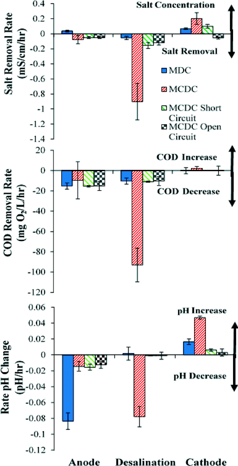 | ||
| Fig. 2 Rate changes per hour in salt removal, COD, and pH for all three chambers of the MCDC and MDC, as well as two control reactors for 5 data sets. Salt removal rate was based on conductivity changes, with positive values indicating salt accumulation and negative values indicating salt removal. For the COD removal rate, positive values indicate COD increase and negative values indicate COD removal. Changes in pH are shown, with positive values indicating pH increase and negative values indicating pH decrease. | ||
When MCDC was operated in negative control mode, where the electrode assemblies were connected in short circuit, the performance of the desalination chamber dropped to 0.1 mS cm−1 h−1, which is similar to the desalination rate in the MDC. This indicates that it was the electrical adsorption that led to the faster desalination rate. The MCDC open circuit control showed similar results to the negative control, with a removal of 0.15 mS cm−1 h−1. Both controls were operated to elucidate the effects of reactor configuration on overall performance. Results indicate a trivial contribution from reactor configuration on system performance. The MCDC desalination chamber ion removal rate is the fastest because of the high surface area and small distance for ion migration. By comparison, the low desalination rate in the MDC middle chamber was believed to be due to the low concentration gradient between the three chambers in MDC. Previous studies showed that high concentration gradients contribute significantly in MDC performance, and molecular diffusion across a membrane in electrodialysis could contribute up to 25% of the total ion flux.33,34
Because the MCDC uses two cation exchange membranes, ions migrate from the anode chamber to the desalination chamber and then to the cathode chamber to balance the transfer of electrons from the anode to the cathode. This is believed to be the reason that the cathode chamber conductivity increased for both MDC and MCDC because it was found that such increases were proportional to the salt migration rate from the desalination chamber to the cathode chamber. The ion increase in the MDC anode chamber was expected, as the MDC configuration does not completely remove ions but rather ions migrate away from the middle chamber to the other chambers.
One of the most interesting findings in this study is illustrated in Fig. 2. It was originally hypothesized that organics would be removed in the anode chamber and salts would be removed in the desalination chamber. The results indeed presented that both MDC and MCDC anode chambers removed about 50–80% of COD at a similar rate of 40 mg of COD per liter per hour, but more COD was found to be actually removed in the desalination chamber of the MCDC at a much faster rate, ranging from 100 to 160 mg of COD per liter per hour, which is faster than any other chambers investigated. Unlike the anode chambers which oxidize the organic faction of the COD to CO2 by microbial activities, the COD removed in the desalination chamber is electrochemically removed through adsorption. The high surface area CDI module is believed to contribute to the faster removal rate, but further analysis will need to be conducted to quantify the contribution. The capacity of the CDI module to remove organic carbon was previously demonstrated in produced water treatment,4 and it was suggested that potentially any charged organic molecule could be removed using capacitive deionization. Almost no COD was removed from the MDC desalination chamber or the cathode chambers of both configurations.
The pH changes in the three chambers between the MDC and MCDC also showed interesting though not significant differences. As shown in Fig. 2, the anode chamber pH in the MCDC decreased by 0.01 pH units per hour while the pH in MDC decreased by 0.08 pH units per hour. However, the MDC had little change in pH in the desalination chamber, while the MCDC decreased by 0.08 pH units per hour. In the cathode chamber, the MDC increased by 0.03 pH units per hour while the MCDC increased by 0.04 pH units per hour. These results indicate that MCDC configuration can reduce pH changes in the anode with a different set of membranes, while pH change in the MCDC middle chamber was more significant. Fluctuations in pH in CDI units have been observed, and the causes were potentially linked to water hydrolysis.35 Given no microbial functions were expected in the middle chamber, such pH changes are not of much concern as they are in the anode chamber.
Power production and MCDC regeneration energy harvesting
Fig. 3 shows the comparison of the operational cycles and voltage generation between MCDC and MDC during one MDC cycle period, and the graph inset shows three consecutive cycles of the MDC. The voltage was measured on a 30 minute interval and error bars were based on 6 consecutive cycles. While the MDC was operated in longer cycles of approximately 40–70 hours based on anode COD removal, the MCDC was operated in much shorter desalination and regeneration cycles based on ion adsorption in the desalination chamber. For each repetitive MCDC cycle, the voltage across the CDI module reached a maximum value of 558 mV, with an average of 530 mV. Anode and cathode potentials versus an Ag/AgCl reference electrode can be seen in the ESI† (Fig. S2). Regeneration of the MCDC in the experiment was achieved by either connecting the CDI modules in short circuit or connecting them with a charge pump for in situ energy harvesting to a 12 F external capacitor. The charge pump is a simple electrical circuit which passively collects energy.18 Energy harvested with the charge pump was not due to capacitive mixing because the energy was harvested without use of a low-salinity electrolyte. Energy harvesting was not conducted for the advanced study or for the MDC. For the same normalized desalination period, the energy stored on the MCDC CDI module was 1789 mJ g−1 ACC, which was calculated based on the coulombs transferred to the CDI module during middle chamber desalination.36,37 The energy harvesting coulombic efficiency was calculated at 0.94%, which indicates that the use of a charge pump is not sufficient for energy harvesting during the regeneration step. Further research will need to be conducted to improve this energy extraction efficiency.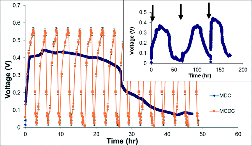 | ||
| Fig. 3 Electrical charges formed on the MCDC and voltage profile of the MDC. Major graph shows a full cycle of MDC, and for the same period, multiple cycles of MCDC operation were performed. Graph inset shows three cycles of MDC operation, with arrows indicating electrolyte change and the last cycle used in the main graph. | ||
For the MDC configuration, a typical voltage profile was generated across the 1000 Ω resistor with a maximum voltage of 450 mV. The voltage increased rather fast in the MDC within the first 3–5 hours then stabilized until organic availability became limited in the anode chamber, which caused the voltage decline. The maximum current produced in the MDC reactor was 450 μA, which is comparable to previous studies that used synthetic media and artificial salt water.18,19,38 The maximum current calculated for the MCDC was 1089 μA, and both current profiles can be found in the ESI† (Fig. S1). More fluctuation in power output was observed compared to previous lab studies, which is believed to be due to the use of produced water with complex constituents. This fluctuation in power output is the main reason for the large standard deviation error bars in Fig. 2.
Advanced desalination capacity and rate of the MCDC system
Following the comparative feasibility study, a more thorough investigation into the capacity of MCDC was performed. It was observed in the comparative study that faster cycles in MCDC can result in higher desalination efficiency. Shorter 1 hour desalination and 20 minute regeneration cycles were performed based on the results from the comparative study. Fig. 4 shows the TDS and COD removal in three consecutive cycles of operation. Compared with Fig. 2, where removal rates were compared in one cycle, Fig. 4 shows the average ion removal of a typical 4 hour operation with three consecutive cycles. It was determined from control tests that physical adsorption accounted for approximately 40% of the TDS removed and electrical adsorption contributed to 60% of the removal. This distribution is similar to previous results using synthetic salt water containing 10 g L−1 NaCl.24 The majority of the salts were removed in the desalination chamber, with 65% of the TDS being removed in three cycles. This represents a 10600 mg L−1 TDS drop in 4 hours (2650 mg of TDS per liter per hour), which is dramatically faster than MDC. The adsorption capacity decreased over successive cycles mainly due to the reduced regeneration efficiency that cannot restore all adsorption capacities. This loss in capacity has been observed in most CDI studies.39 With improvements in reactor design and operation, the loss of capacitance can be minimized; if the applied electrical potential is reversed, the electrodes can be fully recovered.37 The change in pH for the anode and desalination chambers was similar to the pH change in the comparative study. The change in pH for the cathode chamber when it switched to 100% produced water had a larger increase in pH (0.2 ± 0.1 pH units per hour) than that in the comparative study (0.003–0.04 pH units per hour), but the change was not significant due to the natural buffer capability of the produced water.
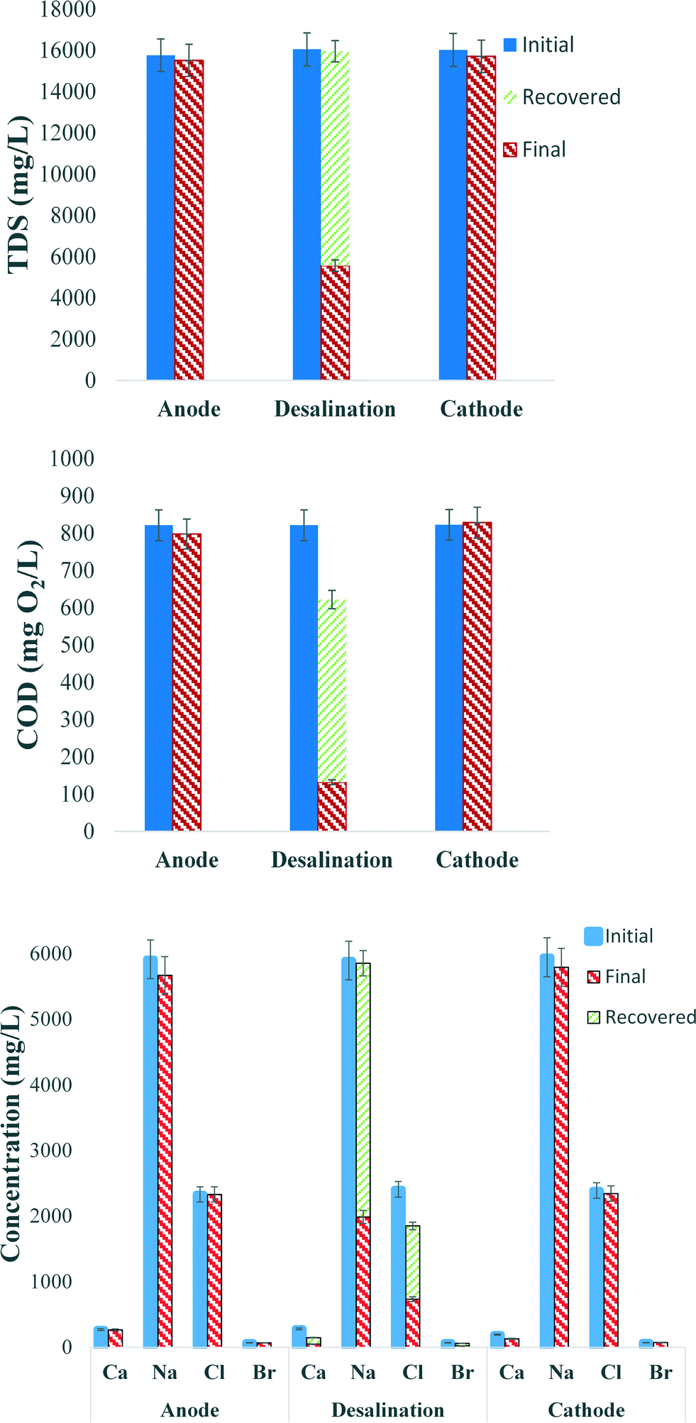 | ||
| Fig. 4 The removal and recovery of TDS, COD, and four predominant ions in the three MCDC chambers in three successive cycles under advanced operating conditions. The concentration difference between each blue bar and red bar indicates the level of removal of a specific parameter, and the green bar shows the percentage of recovery. The data presented here are from three consecutive runs. | ||
The removal of COD in successive MCDC cycles is shown in Fig. 4. During the three cycles, the anode chamber showed a COD removal of 20 mg L−1 during 4 hours, while the desalination chamber showed a COD removal of 660 mg L−1 with 83% removal efficiency during the same period. As shown in Fig. 4, after MCDC regeneration, 75% of the COD that was removed during desalination was fully recovered. It is quite clear that the organic removal in the desalination chamber was due to physical and electrical adsorption, which is much faster than the microbial oxidation in the anode chamber. There was approximately 25% of the COD that was not recovered, but no detectable COD was found on the ACC electrode after regeneration, and it was hypothesized that they were lost due to electrochemical oxidation. Even though COD adsorption on the CDI is not a permanent removal method, it fulfills the goal of quickly removing organic carbon from the desalinated solution and allows faster produced water treatment, which is considered very important in the industry. The adsorbed COD can then be concentrated during regeneration and served as electron donors for microbial metabolisms. This is beneficial to the anode because low electron donor availability has been considered an issue for MDC applications.
Fig. 4 also shows the four predominant ion concentrations for all three chambers, initial, final or after desalination, and after regeneration, to illustrate the ion balance over the course of desalination. While the anode and cathode showed limited ion removal, the desalination chamber showed significant removal of all species. Sodium and chloride concentrations make up a majority of the TDS in the produced water and were predominantly removed. More than 66.3% of the sodium was removed, and then 98.9% of the removed sodium could be recovered during regeneration. Similar rates were observed for chloride (69.5% in removal and 66.7% for recovery). An average of 82% of the calcium and 69% of the bromide were removed, and the recovery for calcium was 42% and for bromide was 81%. The lower recovery rate for calcium may be due to its hardness nature, which has been reported more difficult to desorb from the media.20 However, by reversing the polarity of the applied potential to the CDI, numerous studies have shown that the electrodes can be fully regenerated, and the MCDC had been operated for more than 300 cycles without showing significant decrease in regeneration performance. The reactor CE was calculated to be 21.4%, which is similar to previous studies, especially those that used real industrial wastewater.15,22,24 The reactor CE will be highly dependent upon the organic carbon characteristics of the specific produced water.
Additionally, fluorescence excitation–emission matrix (F-EEM) spectroscopy was used to investigate the changes of fluorescing compounds in the MCDC desalination chamber from the starting point to the end of the three desalination cycles. The excitation and emission contour map is generated by plotting each value against each other. Generally the F-EEM is classified into five different regions. Zones 1 and 2 are for aromatic proteins, zone 3 is for fulvic acid-like compounds, zone 4 is for soluble microbial products, and zone 5 is for humic acid-like organics. Fig. 5A and B show distinct differences in fluorescence intensity, which indicate that after the cycles, a majority of aromatic proteins and soluble microbial byproduct-like materials have been removed. A separate study focusing on using F-EEM and other tools on produced water organic removal can be found in the study by Stoll et al.40
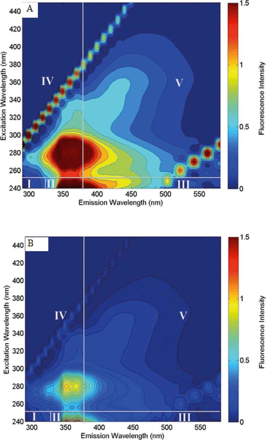 | ||
| Fig. 5 Fluorescence excitation–emission matrix (F-EEM) shows fluorescing organic removal from produced water by the MCDC desalination chamber. (A) F-EEM matrix before treatment and (B) F-EEM matrix after treatment cycles. Images were generated from a prewritten MATLAB program. Contour lines were set at 50 and a maximum intensity of 10. | ||
Outlook
Due to the pressing health and safety concerns associated with unconventional natural gas exploration and production, the oil and gas industry is searching for on-site treatment and reuse options for produced water to replace deep well injection, open pond evaporation, or truck transportation and treatment. In this context, simple, effective, and low-cost treatment processes are urgently needed. For removing both organic pollutants and salts from produced water, current solutions require a long chain of biological and membrane processes with high energy demand. This study presents that microbial desalination systems can be a new approach to solve such problems, also with the benefit of energy output. Traditional microbial fuel cell-based MDC processes could accomplish organic matter and salt removal, but the rates have been slow, and the amount of concentrates generated can be larger than the desalinated water. The MCDC system largely overcame these challenges by integrating capacitive deionization into the system, which increased the desalination rate 18 times and the COD removal rate 5 times faster than the traditional MDC.Both MDC and MCDC require a certain amount of organics in the produced water, so microorganisms can oxidize these electron donors to drive desalination. This requirement may limit their applications for certain produced waters, such as those from formations with very high salinity but low organics, but because MCDC can accumulate and recover organics from the CDI modules, the recovered COD can be recycled back to the anode chamber to alleviate potential shortage of organics. Because the rate of microbial desalination is correlated with the initial salt and organic concentrations, it may not be as efficient as the membrane processes in producing directly reusable water (TDS <500 mg L−1). However, it can be an efficient pretreatment for membrane systems to reduce organic and salinity loadings and prevent membrane fouling, as well as provide renewable power sources. Additionally, the deionized water can be replaced with treated effluent; the production of a concentrated brine solution from the MCDC system may be a value-added product, as opposed to cost, with industries and municipalities requiring salt solutions for product processing. Overall, with further research and development, the unique feature of simultaneous organic matter and salt removal and energy production will help microbial desalination systems play an important role in produced water management.
Acknowledgements
This work was supported by the US Office of Naval Research under Award N000141310901 and US National Science Foundation under Award CBET-1235848. We appreciate Dr. Tzahi Y. Cath, Colorado School of Mines, for proving produced water samples.Notes and references
-
C. E. Clark and J. A. Veil, Produced Water Volumes and Management Practices in the United States, National Energy Technology Laboratory, 2009 Search PubMed
.
- EIA, Annual Energy Outlook 2013 with Projections to 2040. Report #:DOE/EIA-0383(2013). Prepared by the U.S. Energy Information Administration (EIA). Release Date: April, 2013. Available at: <http://www.eia.gov/forecasts/aeo/pdf/0383(2013).pdf>
- P. Xu, J. E. Drewes and D. Heil, Desalination, 2008, 225, 139–155 CrossRef CAS PubMed
- P. Xu, J. E. Drewes, D. Heil and G. Wang, Water Res., 2008, 42, 2605–2617 CrossRef CAS PubMed
- GWPC and ALL, 2009.
- K. L. Hickenbottom, N. T. Hancock, N. R. Hutchings, E. W. Appleton, E. G. Beaudry, P. Xu and T. Y. Cath, Desalination, 2013, 312, 60–66 CrossRef CAS PubMed
- P. Xu and J. E. Drewes, Sep. Purif. Technol., 2006, 52, 67–76 CrossRef CAS PubMed
- K. G. Dahm, K. L. Guerra, P. Xu and J. R. E. Drewes, Environ. Sci. Technol., 2011, 45, 7655–7663 CrossRef CAS PubMed
- D. L. Shaffer, L. H. Arias Chavez, M. Ben-Sasson, S. Romero-Vargas Castrillón, N. Y. Yip and M. Elimelech, Environ. Sci. Technol., 2013, 47, 9569–9583 CrossRef CAS PubMed
- D. M. Kargbo, R. G. Wilhelm and D. J. Campbell, Environ. Sci. Technol., 2010, 44, 5679–5684 CrossRef CAS PubMed
- S. Yoshie, N. Noda, S. Tsuneda, A. Hirata and Y. Inamori, Appl. Environ. Microbiol., 2004, 70, 3152–3157 CrossRef CAS
- K. L. Hickenbottom, N. T. Hancock, N. R. Hutchings, E. W. Appleton, E. G. Beaudry, P. Xu and T. Y. Cath, Desalination, 2013, 312, 60–66 CrossRef CAS PubMed
-
J. E. Drewes, N. T. Hancock, K. L. Benko, K. Dahm, P. Xu, D. Heil and T. Y. Cath, Treatment of coalbed methane produced water. 126–128, Colorado School of Mines, Golden, CO., 2009 Search PubMed
- S. Mondal and S. R. Wickramasinghe, J. Membr. Sci., 2008, 322, 162–170 CrossRef CAS PubMed
- H. Wang and Z. J. Ren, Biotechnol. Adv., 2013, 31, 1796–1807 CrossRef CAS PubMed
- P. Liang, L. Yuan, X. Yang, S. Zhou and X. Huang, Water Res., 2013, 47, 2523–2530 CrossRef CAS PubMed
- H. Luo, P. E. Jenkins and Z. Ren, Environ. Sci. Technol., 2011, 45, 340–344 CrossRef CAS PubMed
- H. Wang, J.-D. Park and Z. Ren, Environ. Sci. Technol., 2012, 46, 5247–5252 CrossRef CAS PubMed
- X. X. Cao, X. Huang, P. Liang, K. Xiao, Y. J. Zhou, X. Y. Zhang and B. E. Logan, Environ. Sci. Technol., 2009, 43, 7148–7152 CrossRef CAS
- H. Luo, P. Xu, P. E. Jenkins and Z. Ren, J. Membr. Sci., 2012, 409, 16–23 CrossRef PubMed
- H. Luo, P. Xu and Z. Ren, Bioresour. Technol., 2012, 120, 187–193 CrossRef CAS PubMed
- K. S. Jacobson, D. M. Drew and Z. He, Environ. Sci. Technol., 2011, 45, 4652–4657 CrossRef CAS PubMed
- Y. Kim and B. E. Logan, Desalination, 2013, 308, 122–130 CrossRef CAS PubMed
- C. Forrestal, P. Xu and Z. Ren, Energy Environ. Sci., 2012, 5, 7161–7167 CAS
- C. Forrestal, P. Xu, P. E. Jenkins and Z. Ren, Bioresour. Technol., 2012, 120, 332–336 CrossRef CAS PubMed
- P. M. Biesheuvel and M. Z. Bazant, Phys. Rev. E: Stat., Nonlinear, Soft Matter Phys., 2010, 81, 031502 CrossRef CAS
- L. Yuan, X. Yang, P. Liang, L. Wang, Z.-H. Huang, J. Wei and X. Huang, Bioresour. Technol., 2012, 110, 735–738 CrossRef CAS PubMed
- C. Feng, C.-H. Hou, S. Chen and C.-P. Yu, Chemosphere, 2013, 91, 623–628 CrossRef CAS PubMed
- M. C. Hatzell, R. D. Cusick and B. E. Logan, Energy Environ. Sci., 2014, 7, 1159–1165 CAS
- H. Wang, M. Davidson, Y. Zuo and Z. Ren, J. Power Sources, 2011, 196, 5863–5866 CrossRef CAS PubMed
- J.-D. Park and Z. Ren, J. Power Sources, 2012, 205, 151–156 CrossRef CAS PubMed
- H. Luo, P. Xu, T. M. Roane, P. E. Jenkins and Z. Ren, Bioresour. Technol., 2012, 105, 60–66 CrossRef CAS PubMed
- M. P. Mier, R. Ibañez and I. Ortiz, Sep. Purif. Technol., 2008, 59, 197–205 CrossRef CAS PubMed
- Y. Kim and B. E. Logan, Environ. Sci. Technol., 2011, 45, 5840–5845 CrossRef CAS PubMed
- S. J. Seo, H. Jeon, J. K. Lee, G. Y. Kim, D. Park, H. Nojima, J. Lee and S. H. Moon, Water Res., 2010, 44, 2267–2275 CrossRef CAS PubMed
- P. M. Biesheuvel, J. Colloid Interface Sci., 2009, 332, 258–264 CrossRef CAS PubMed
- M. A. Anderson, A. L. Cudero and J. Palma, Electrochim. Acta, 2010, 55, 3845–3856 CrossRef CAS PubMed
- K. S. Jacobson, D. M. Drew and Z. He, Bioresour. Technol., 2011, 102, 376–380 CrossRef CAS PubMed
- Y. Oren, Desalination, 2008, 228, 10–29 CrossRef CAS PubMed
- Z. A. Stoll, C. Forrestal, Z. Ren and P. Xu, J. Hazard. Mater., 2014 Search PubMed
Footnote |
| † Electronic supplementary information (ESI) available. See DOI: 10.1039/c4ew00050a |
| This journal is © The Royal Society of Chemistry 2015 |