An economical upflow bio-filter circuit (UBFC): a biocatalyst microbial fuel cell for sulfate–sulfide rich wastewater treatment
Received
1st August 2014
, Accepted 4th November 2014
First published on 21st November 2014
Abstract
In this study of the UBFC, a biocatalyst MFC was applied to remove sulfate–sulfide in wastewater (initial concentration: 350–450 mg L−1). Two sizes of the UBFC (40 L and 250 L) were scaled up from the original trial size (4 L) and their capability and feasibility were tested. The results revealed that the sulfide removal efficiency was over 70% without chemical and nutritional addition. The minimum cost of the 250 L plant prototype was US$1280 m−3 and the operating power consumption was less than 0.32 kWh m−3. The biofactors that enhance the efficiency of the economical UBFC are biocatalyst producers such as the Clostridium sp., Pseudomonas sp., Limnobacter sp. and Sinorhizobium sp. and sulfate–sulfide reducers such as the Sphaerotilus sp. and Limnobacter sp. This work suggests that the economical UBFC plant prototype has potential for application in sulfate–sulfide rich wastewater treatment.
Water impact
An UBFC microbial fuel cell is a green technology reactor composed of biomaterials and biocatalysts. A bioelectrochemical technique was applied in this design to treat wastewater without chemical and nutritional addition. This invention enabled to remove COD up to 26.67 g L−1 per day and removed about 70% of sulphate–sulfide. Its efficiency was about 3–20 times higher than that of other existing technologies. The cost of this invention was US$1280 m−3 (close to that of an anaerobic digester). Additionally, the power consumption was less than 0.32 kWh m−3 (close to that of aerobic pond operation). The UBFC microbial fuel cell could be a novel technology for wastewater treatment in the near future which can solve the water pollution crisis faster and provide sufficient fresh water for living.
|
A. Introduction
The reduction of sulfate to sulfide under anaerobic conditions has a negative effect on human health and on the environment through the generation of toxic gas and through metal corrosion.1 Sulfate and sulfide ions are contained in hazardous waste from latex sheet manufacture and can be released to local natural reservoirs causing a serious problem in the south of Thailand. At present many agencies are interested in finding a solution to this problem because the concentration of sulfate and sulfide ions exceeds the legal standard many times. Generally, small rubber latex sheet plants release wastewater which contains a high concentration of sulfate–sulfide at about 350–450 mg L−1;2 the standard for sulfate is <200 mg per L SO42− and that for sulfide is <1.0 mg per L S2−). Current practice in wastewater treatment makes use of aerobic ponds that need large areas and release toxic gas with an unpleasant odour. Sulfate–sulfide rich wastewater can also be discharged from this process causing water pollution problems in local natural waters. Many wastewater treatment technologies have been applied to reduce this problem such as the sulfate reduction reactor (SRR), which has been used to treat sulfate rich rubber wastewater from concentrated latex and skim crepe processes.3 However, high concentration of H2S (2.4 mM) is a common problem in many bioreactors since it has a toxic effect on organism growth.4 Once the cells stop growing, the biomass is completely washed out from the reactor. The sulfur compounds cannot be removed separately by either anaerobic or aerobic treatment. They can be treated by electrochemical techniques to convert them into insoluble solid forms like elemental sulfur5–10 or pyrite.11–14
Recently, microbial fuel cells (MFC) have been developed for wastewater treatment in which bioelectrochemical methods are used to mineralize organic and inorganic matters to non-toxic forms and at the same time generate electricity. This approach has a number of advantages over existing methods including superior efficiency, minimal area requirements, less maintenance and high stability. However, their application is still limited because of the high cost of the materials needed to build the reactor, notably the graphite electrodes, the metal catalyst (platinum or gold), the mediators and the membrane.15 Other previous reactor designs, have been developed as less expensive substitutes such as membrane-less,16–19 single chamber air cathode,20–22 activated carbon fiber23–25 membraneless and mediatorless,25,26 carbon fiber brush electrode,27–29 earthen pot membrane.30
Rabaey and others8 have investigated electricity generation from sulfide in two-chamber MFCs. In their study, sulfide was removed mainly through the oxidation of sulfide to sulfur on the anode surface. Deposition of sulfur on the anode surfaces has also been demonstrated in sediment MFCs operated in marine environments where the sulfate concentration is normally very high.31–34 The reactions for S formation are shown in eqn (1)–(3):35
| | | SO42− + 10H+ → H2S + 4H2O + 10e− | (1) |
Summary:
| | | SO42− + 8H+ → S0 + 4H2O + 8e− | (3) |
The reaction for pyrite formation is shown in
eqn (4):
14| | | Fe + 2SO42− + 16H+ → FeS2 + 8H2O | (4) |
Overall, the biocatalytic removal of H2S offers the following advantages over conventional physicochemical processes: (1) no chemical additives; (2) lower energy requirements; (3) no need for a tail gas plant; (4) no sulfur waste disposal; (5) no corrosion problems, and (6) it is a less expensive process. In addition, biological systems produce elemental sulfur and microbial biomass as end products.36
Previously, a low cost UASB (a biocatalyst microbial fuel cell) was employed to treat biodiesel wastewater in which 15![[thin space (1/6-em)]](https://www.rsc.org/images/entities/char_2009.gif) 000 mg COD L−1 per day can be treated without nutritional supplement.25 The efficiency of microbial fuel cells in digesting organic substances in wastewater is about 3–20 times higher than that of the current technology.25,29 The economical UBFC25 was modified to be a prototype for sulfate–sulfide rich wastewater treatment in a rubber latex sheet process industrial plant. In this report, the feasibility and economical strategy for pilot and plant scale applications are discussed.
000 mg COD L−1 per day can be treated without nutritional supplement.25 The efficiency of microbial fuel cells in digesting organic substances in wastewater is about 3–20 times higher than that of the current technology.25,29 The economical UBFC25 was modified to be a prototype for sulfate–sulfide rich wastewater treatment in a rubber latex sheet process industrial plant. In this report, the feasibility and economical strategy for pilot and plant scale applications are discussed.
B. Materials and methods
1. UBFC construction
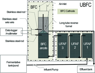
1.2. A 40 L pilot scale UBFC prototype.
This reactor was scaled up in almost the same ratio as the laboratory scale reactor, but the tube material was changed from plastic (polypropylene) to PVC. The void volume of the reactor was 21 ± 0.5 L.
1.3. A 250 L plant scale UBFC prototype.
This plant prototype was built up in almost the same ratio as the pilot scale prototype and a PVC reactor was also used. However, to reduce the cost of the plant prototype, the immobilized ICFBs were fixed in place by four iron poles (Ø 10 mm, length 800 mm) covered with 1.25 kg of natural carbon fiber (surface area, 1.07 m2 g−1). In addition, both anode and cathode nodes were increased from one to four in order to reduce the electron transfer distance (Fig. 2). The performance of the reactor using this new immobilized base was determined. It was found that the plant scale performance using four iron poles covered with natural carbon fiber was not significantly different from that of the ICFB immobilized base. The void volume was 130 ± 6.0 L.
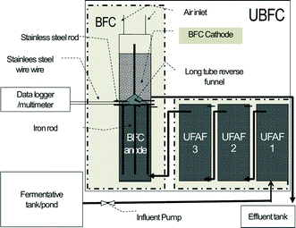 |
| | Fig. 2 Schematic of a plant scale UBFC prototype. | |
2. Rubber latex sheet wastewater (RLW) properties
The crude RLW normally has a COD (chemical oxygen demand) value between 25![[thin space (1/6-em)]](https://www.rsc.org/images/entities/char_2009.gif) 000–35
000–35![[thin space (1/6-em)]](https://www.rsc.org/images/entities/char_2009.gif) 000 mg L−1 (the standard is <120 mg COD L−1) and contains 350–450 mg L−1 sulfate and sulfide (the standard for sulfate is <200 mg per L SO42− and that for sulfide is <1.0 mg per L S2−), with 2000–3000 g L−1 suspended solid (SS) (the standard is <50 mg SS L−1). It is acidic with a pH level between 4–6 (standard: 6.5–8.0 (ref. 2)). The first aerobic pond on-site was used as a fermentation tank as shown in Fig. 1, and the influent was taken from the end point of the pond. It had COD, sulfate and sulfide concentrations of 4500 ± 500 mg L−1, 320 ± 1.67 mg L−1, and 1.0 ± 0.12 mg L−1, respectively, and the pH level was 6.0–6.5.
000 mg L−1 (the standard is <120 mg COD L−1) and contains 350–450 mg L−1 sulfate and sulfide (the standard for sulfate is <200 mg per L SO42− and that for sulfide is <1.0 mg per L S2−), with 2000–3000 g L−1 suspended solid (SS) (the standard is <50 mg SS L−1). It is acidic with a pH level between 4–6 (standard: 6.5–8.0 (ref. 2)). The first aerobic pond on-site was used as a fermentation tank as shown in Fig. 1, and the influent was taken from the end point of the pond. It had COD, sulfate and sulfide concentrations of 4500 ± 500 mg L−1, 320 ± 1.67 mg L−1, and 1.0 ± 0.12 mg L−1, respectively, and the pH level was 6.0–6.5.
3. UBFC inoculation and operation
To prepare the immobilized base, the ICFBs were soaked in the suspended sludge mixture or mixed liquor suspended solids (MLSS) with a concentration of 24.41 ± 0.23 g L−1 under anaerobic conditions for three days. Subsequently, they were set in four anaerobic chambers. At the same time, in an aerobic cathode chamber, GAC was soaked in the suspended sludge mixture for three days and then aerated at 200 mL min−1. The RLW was fed into the UBFC as a starter culture and left for a week until the open circuit voltage was at least 0.5 V. The experiment was conducted at ambient temperature (30 ± 5 °C).
4. Experimental operation
4.1. 4 L laboratory scale UBFC prototype and 40 L pilot scale UBFC prototype operations.
Both the 4 L laboratory scale and the 40 L pilot scale UBFCs were fed step by step with RLW at various organic loading rates (OLR) (5, 10, 15, 20, 30 and 45 g L−1 per day). The experiment was conducted at pH 6.6–7.5, with the cathode chamber aerated at 200 mL min−1. Each experiment was performed for three days or until the voltage signal became stable. Samples of the influent and effluent were taken in triplicate at the beginning and the end of the third day. Each sample was analysed to determine the COD, sulfate and sulfide concentrations. The power potential of the laboratory scale reactor was tested at the Microbial Fuel Cell Laboratory, Thaksin University, Phatthalung, Thailand. It was recorded every 100 seconds using a data logger program (National Instruments USB-6008). The pilot scale reactor was assessed once a week using a multimeter (Pro'sKit, 303-150NCS) through on-site testing at Bantungsangthong village, Amphur Thamode, Phatthalung province, Thailand.
4.2. Development of immobilized materials.
For the comparative study of the performance of the systems between used ICFBs (see 1.1) and four iron poles covered with 1.25 kg of natural carbon fiber (see 1.3) as anode materials. Each iron pole was directly connected to a stainless steel port to increase the electron transfer efficiency.
4.3. A 250 L plant scale UBFC prototype operation.
The plant scale UBFC prototype was set up in Bantungsangthong village, Amphur Thamode, Phatthalung province, Thailand. It was fed with RLW at an OLR of 5.0 g L−1 per day (the optimum condition predicted by results from the laboratory scale test). Each experiment lasted for one week or until the voltage signal became stable. The influent and effluent samples were taken in triplicate at the beginning and the end of the week to analyse their COD, sulfate and sulfide concentrations. The power potential was measured using a multimeter (Pro'sKit, 303-150NCS) and recorded on-site once a week. After three months of use, the sulfur compound as a solid deposit on the cathode GAC surface was analysed.
5. Analysis and calculations
The electric current and power were calculated using eqn (5) and (6):where V is the cell voltage (V) and R is the external resistance (Ω). The density of current and power was calculated by dividing them with an anode volume. The HRT and OLR were calculated as described in eqn (7) and (8):| | | HRT (min) = [reactor volume (L)]/[influent flow rate (L min−1)] | (7) |
| | | OLR (g COD L−1 per day) = [COD concentration (g COD L−1)]/[HRT (day)] | (8) |
The COD concentration, TS and VS were measured using standard methods.37 The volatile fatty acids (VFAs) were analysed by GC-FID (HP 6850).38 Sulfate and sulfide were measured using the turbidimetric method37 and the methylene blue method of Pachmayr,39 respectively. The energy-dispersive X-ray spectroscopy (EDX) method40 was used to determine the sulfur element that was found on the electrode surfaces. Moreover, DGGE genetic analysis was used to identify the microbial communities in both BFC anode and cathode chambers.41 A complete block design (CBD) and Duncan's test were used for statistical analysis.
C. Results and discussion
1. A 4 L laboratory scale UBFC prototype
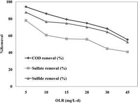
The optimum condition for the sulfate–sulfide rich wastewater treatment on the laboratory scale UBFC was found to be at the lowest OLR of 5.0 ± 0.71 g COD L−1 per day. The results showed that the removal efficiency levels of COD, sulfate and sulfide were 94.18%, 77.97% and 87.73%, respectively, without the need for any costly chemical and nutritional addition (Fig. 3). However, the maximum potential was 0.6 V at a 10 kΩ external resistance or 0.012 mW at the highest OLR of 30 g L−1 per day, which is negligible for use; thus, this has to be studied further. The whole system cost was around US$6.68 L−1 (excluding the pump) and the operating power consumption was less than 8.25 Wh L−1.
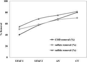 |
| | Fig. 3 The COD, sulfate and sulfide removal efficiency (%) of a laboratory scale UBFC fed with RLW at various OLR for a closed circuit with a 10 kΩ external resistance. | |
2. A 40 L pilot scale UBFC prototype
2.1 Reactor
The 40 L reactor was built up using 125 mm internal diameter PVC pipes. It was fed with RLW at an OLR of 5.0 ± 0.71 g L−1 per day (the optimum condition indicated by the laboratory scale test). The removal efficiencies of COD, sulfate and sulfide were 79.94%, 70.16% and 81.55%, respectively (Fig. 4). These results indicated lower efficiency than that obtained using the laboratory reactor; this was probably due to the longer distance between the anode and the cathode causing a reduction in the biochemical conversion. The whole pilot scale cost was US$8.11 L−1 (including the pump) and the operating power consumption was around 1.0 Wh L−1.
 |
| | Fig. 4 The COD, sulfate and sulfide removal efficiency (%) of a pilot scale UBFC fed with RLW at an OLR of 5.0 ± 0.71 g COD L−1 per day for a closed circuit with a 30 kΩ external resistance. | |
2.2. Development of immobilized materials
The performance of the natural carbon fiber was not significantly different from that of ICFBs (Fig. 5). The nature of carbon fiber before and after 3 months of use was studied by scanning electron microscopy (Fig. 6). The biofilm on its surface was found to be well developed; hence the natural carbon fiber can substitute for ICFBs with reduced cost.
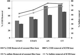 |
| | Fig. 5 Comparison of COD and sulfate removal efficiency (%) using an ICFB immobilized base and a coconut fiber immobilized base for pilot scale UBFCs fed with RLW at an OLR of 5.0 ± 0.71 g COD L−1 per day for a closed circuit with a 30 kΩ external resistance. | |
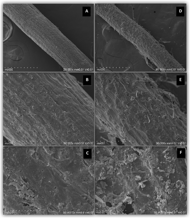 |
| | Fig. 6 Scanning Electron Microscopy (SEM) images of carbon fiber before immobilized (×150SE (A), ×500SE (B), ×2000SE (C)) and after immobilized (×150SE (D), ×500SE (E), ×2000SE (F)). | |
2.3. Effect of aeration in the cathode part
The pilot scale UBFC performance revealed promising power generation when operated without aeration in the cathode. The results obtained with and without aeration in the cathode differed significantly (Fig. 7). Therefore, the pilot UBFC was used without aeration in the cathode. Each experiment was operated for a week or until the voltage signal became stable. The maximum potential was found to be 0.430 ± 0.050 V at 30 kΩ external resistance connection. This suggests that a bioelectrochemical reaction plays a role in sulfur oxidizing and sulfate reducing microbial communities. The sulfide oxidizing communities act as H2S scavengers which oxidize the reduced sulfur compounds at the oxic/anoxic interface and prevent their diffusion to the atmosphere. Despite being subjected to changes in the environmental conditions, these complex communities are able to cope with these changes and maintain stable oxidation rates.42 Recently, Kantachote and coworkers43 described that the special features of bacteria in the sulfur rich medium were facultative anaerobic growth and catalase/oxidase activity.44
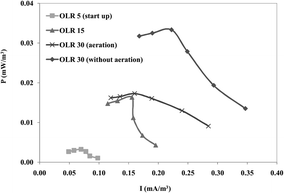 |
| | Fig. 7 Power generation performance (mW m−3) of the pilot scale prototype under various conditions. | |
3. A 250 L plant scale UBFC prototype
The reactor was assembled using 250 mm internal diameter PVC pipes. It was operated at an influent flow rate of 1.2 m3 per day, corresponding to an OLR of 5.0 ± 0.71 g COD L−1 per day, and a closed circuit with an external resistance of 30 kΩ.
The COD, sulfate and sulfide removal efficiencies of the plant scale UBFC were 94.11%, 76.24% and 77.32%, respectively (Fig. 8). The maximum power was 0.053 mW (1.3 V at a 30 kΩ external resistance), which is still insufficient. The treated wastewater contained COD concentration within the standard COD concentration (<120 g COD L−1).45 The increase in the plant scale performance was possibly due to the increased electron transfer ability achieved by inserting the 4 iron poles into the natural carbon fiber base. They functioned as an electron transfer bridge which was directly in contact with the stainless steel port. However, the sulfate and sulfide levels were slightly higher than the standard. Therefore, it was considered that phyto-remediation treatment could reduce the excess and meet discharge allowance.
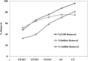 |
| | Fig. 8 The COD, sulfate and sulfide removal efficiency (%) of a pilot scale UBFC fed with RLW at an OLR of 5.0 ± 0.71 g COD L−1 per day for a closed circuit with a 30 kΩ external resistance. | |
The volatile fatty acid composition of the influent of rubber latex sheet in each UBFC column was determined. It was found that the degree of degradation increased along with the order of UBFC columns. The main products were propionic acid, acetic acid and isovaleric acid (Fig. 9). The results showed that the VFAs were effectively removed (56.25%) in the BFC column indicating that the UBFC system shows sufficiently high performance to treat wastewater via a bioelectrochemical technique.
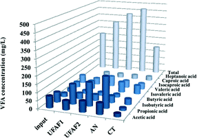 |
| | Fig. 9 Volatile fatty acid composition (mg L−1) of the rubber latex influent in each column of the UBFC reactor. | |
In addition, the sulfur level on the GAC surface in the cathode part was determined by energy dispersive X-ray (EDX) analysis to compare the raw and used GAC (Fig. 10). The composition of plain GAC was 100% carbon while 15% sulfur was found on the used GAC. Hence the UBFC system can convert sulfate–sulfide into insoluble solid sulfur compounds attached on the cathode surface that would allow ease of maintenance.
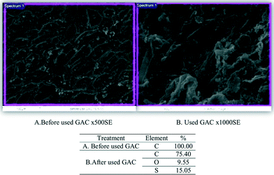 |
| | Fig. 10 Element determination (%) by energy dispersive analysis raw and used GAC. SEM views of the regions analyzed and the analysis of elements held by active charcoal adsorption. | |
The cost of the economical plant prototype was about US$1280 m−3 (including the pump) which was reduced compared to that of the smaller sizes by about 80%. In addition, the power consumption was less than 0.32 kWh m−3. The results indicate that the 250 L plant scale UBFC has high feasibility to be applied in sulfate–sulfide rich wastewater treatment for smallholding rubber latex sheet process industries.
4 DGGE analysis
Fig. 11 elucidates the microbial populations represented in the inoculum sludge from the rubber latex sheet process plant and in the culture from the anode and cathode chambers. The DGGE results show that the Sunxiuqinia sp. (KC337109.1), Comamonas sp. (KC953135.1), uncultured Clostridium sp. (HM153812.1), Pseudomonas sp. (HM478052.1), uncultured Rhizobium sp. (FN908846.1) and uncultured Actinobacterium sp. (EF188333.1) dominated the anode.
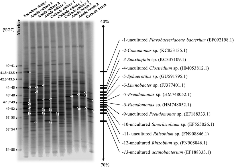 |
| | Fig. 11 DGGE images of the microbial populations represented in the inoculum sludge from the rubber latex sheet process plant, the mass from the culture of the anode and cathode chambers, and the immobilized biofilm from the anode and cathode brush. | |
Normally, the Sunxiuqinia sp. is a facultative anaerobic organoheterotrophic bacterium. Previously, Takai and co-workers46 isolated this species from deep sub-seafloor sediment offshore where high sulfur compounds were detected.32 It might be that the Sunxiuqinia sp. shows symbiosis with sulfate reducing bacteria (SRB) or acts as SRB itself. Unsurprisingly, the Clostridium sp. is known as a biocatalyst producer, which was also found in a previous study.25 The activities of NADH/NADPH peroxidase were detected and are distributed widely in the genus Clostridium.47 Abnormally, the strictly aerobic Pseudomonas sp. and the aerobic uncultured Rhizobium sp. (FN908846.1) were found in the anaerobic anode. Costerton and co-workers48 reported that the Pseudomonas species is commonly found in connection with corrosion. They colonize the metal surface, which was the iron poles in this study, thereby creating oxygen-free environments for anaerobic bacteria, especially sulfate reducers.48,49 While uncultured (could not grow in any media) Rhizobium sp. (FN908846.1) possible came from the natural fiber anode material. The dominant clones of the cathode communities were the Sphaerotilus sp. (GU591795.1), Limnobacter sp. (FJ377401.1) and uncultured Sinorhizobium sp. (EF555026.1). Following the hypothesis, the sulfate reducing bacteria, Sphaerotilus sp., was found. It is an aquatic periphyton organism associated with polluted water and with the capability to deposit elemental sulfur intracellularly in the presence of hydrogen sulfide was found. On the other hand, the Limnobacter sp., a gram-negative, non-spore-forming, aerobic, oxidase- and catalase-positive motile bacterium with a single polar flagella and with the ability to oxidize thiosulfate,50 was seen to act as a sulfate reducer and a biocatalyst producer. Moreover, the symbiosis bacteria like Sinorhizobium sp. was presented. It is a gram-negative nitrogen-fixing bacterium (rhizobium)51 uses a nitrate source to stimulate cellulase activity.52 In this study, the natural fiber brush in the anode could provide dissolved nitrate53 for Sinorhizobium sp. growth at the cathode to generate the cellulase enzyme54 as a biocatalyst.
The biofactors that enhance the efficiency of the economical UBFC are: 1) biocatalyst producers such as the Clostridium sp., Pseudomonas sp., Limnobacter sp. and Sinorhizobium sp. and 2) sulfate–sulfide reducers such as the Sphaerotilus sp. and Limnobacter sp.
Conclusions
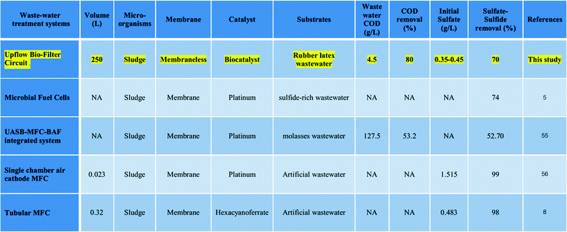
The economical UBFC plant prototype is an example of green technology that uses biomaterials and biocatalysts without chemical and nutritional addition. It enabled the treatment of sulfate–sulfide rich wastewater like other MFCs (Table 1).5,56 The biofactors that enhance the efficiency of the economical UBFC are: 1) biocatalyst producers such as the Clostridium sp., Pseudomonas sp., Limnobacter sp. and Sinorhizobium sp. and 2) sulfate–sulfide reducers such as the Sphaerotilus sp. and Limnobacter sp. The cost of the complete plant prototype was US$1280 m−3 with 70% sulfate–sulfide removal efficiency. In addition, the power consumption was less than 0.32 kWh m−3. The quality of the discharge was within the standard45 for the COD concentration but slightly over the standard for the levels of sulfate–sulfide. The excess can be removed by phytoremediation treatment to meet the discharge allowance. These are the advantages of UBFC technology for the sulfate–sulfide rich wastewater treatment. However, the process generated insufficient power which has to be addressed in further work.
Table 1 Comparison of the sulfate–sulfide removal efficiency of the UBFC system and other microbial fuel cells
Acknowledgements
This research was supported by the Institute of Research and Development for Health of Southern, Thailand. The authors would like to thank Dr. John Pearce from MTEC, NSTDA, Dr. Alan Frederic Geater, Asst. Prof. Dr. Piyarat Boonsawang, Mr. Athirat Rarngnarong, Mr. Adilan Nniman from the Prince of Songkla University and Dr. Maneewan Suwansaard from the Department of Biological Sciences, BGSU for their kind assistance with this work.
Notes and references
- Wikipedia, Sulfide, the free encyclopedia, 2013.
- The-Environment-Protection-Agency, in The Principle Parameters of Water Quality, the Environmental Protection Agency, Ireland, 2001, p. 104 Search PubMed.
- P. Tekasakul and S. Tekasakul, Earozoru Kenkyu, 2006, 21, 122–129 CAS.
- H. V. Gemerden, Arch. Microbiol., 1984, 139, 289–294 CrossRef.
- L. H. Zhang, Y. P. Mao, J. X. Ma, D. M. Li, H. F. Shi, Y. D. Liu and L. K. Cai, Environ. Technol., 2013, 34, 269–274 CrossRef CAS PubMed.
- F. Zhao, N. Rahunen, J. R. Varcoe, A. J. Roberts, C. Avignone-Rossa, A. E. Thumser and R. C. T. Slade, Biosens. Bioelectron., 2009, 24, 1931–1936 CrossRef CAS PubMed.
- M. Sun, Z.-H. Tong, G.-P. Sheng, Y.-Z. Chen, F. Zhang, Z.-X. Mu, H.-L. Wang, R. J. Zeng, X.-W. Liu, H.-Q. Yu, L. Wei and F. Ma, Biosens. Bioelectron., 2010, 26, 470–476 CrossRef CAS PubMed.
- K. Rabaey, K. Van de Sompel, L. Maignien, N. Boon, P. Aelterman, P. Clauwaert, L. De Schamphelaire, H. T. Pham, J. Vermeulen, M. Verhaege, P. Lens and W. Verstraete, Environ. Sci. Technol., 2006, 40, 5218–5224 CrossRef CAS.
- C.-Y. Lee, K.-L. Ho, D.-J. Lee, A. Su and J.-S. Chang, Int. J. Hydrogen Energy, 2012, 37, 15827–15832 CrossRef CAS PubMed.
- S. Jung and J. M. Regan, Appl. Microbiol. Biotechnol., 2007, 77, 393–402 CrossRef CAS PubMed.
- J. P. Gramp, J. M. Bigham, F. S. Jones and O. H. Tuovinen, J. Hazard. Mater., 2010, 175, 1062–1067 CrossRef CAS PubMed.
- A. L. Neal, S. Techkarnjanaruk, A. Dohnalkova, D. McCready, B. M. Peyton and G. G. Geesey, Geochim. Cosmochim. Acta, 2001, 65, 223–235 CrossRef CAS.
- K. M. Moon, H. R. Cho, M. H. Lee, S. K. Shin and S. C. Koh, Met. Mater. Int., 2007, 13, 211–216 CrossRef CAS.
- M. G. Vladimirov, Y. Ryzhkov, V. A. Alekseev, V. A. Bogdanovskaya, M. S. Kritsky and V. A. Otroshchenko, Dokl. Biochem. Biophys., 2002, 385, 205–208 CrossRef CAS.
- Q. Deng, X. Li, J. Zuo, A. Ling and B. E. Logan, J. Power Sources, 2010, 195, 1130–1135 CrossRef CAS PubMed.
- J. K. Jang, T. H. Pham, I. S. Chang, K. H. Kang, H. Moon, K. S. Cho and B. H. Kim, Process Biochem., 2004, 39, 1007–1012 CrossRef CAS.
- H. Moon, I. S. Chang and B. H. Kim, Bioresour. Technol., 2006, 97, 621–627 CrossRef CAS PubMed.
- Z. Hu, J. Power Sources, 2008, 179, 27–33 CrossRef CAS PubMed.
- Z. Du, Q. Li, M. Tong, S. Li and H. Li, Chin. J. Chem. Eng., 2008, 16, 772–777 CrossRef CAS.
- H. Liu, S. Cheng and B. E. Logan, Environ. Sci. Technol., 2005, 39, 658–662 CrossRef CAS.
- C. Sukkasem, S. T. Xua, S. Park, P. Boonsawang and H. Liu, Water Res., 2008, 42, 4743–4750 CrossRef CAS PubMed.
- J. Sun, Y. Hu, Z. Bi and Y. Cao, J. Power Sources, 2009, 187, 471–479 CrossRef CAS PubMed.
- Q. Deng, X. Li, J. Zuo, A. Ling and B. E. Logan, J. Power Sources, 2010, 195, 1130–1135 CrossRef CAS PubMed.
- Z. Du, Q. Li, M. Tong, S. Li and H. Li, Chin. J. Chem. Eng., 2008, 16, 772–777 CrossRef CAS.
- C. Sukkasem, S. Laehlah, A. Hniman, S. O-thong, P. Boonsawang, A. Rarngnarong, M. Nisoa and P. Kirdtongmee, Bioresour. Technol., 2011, 102, 10363–10370 CrossRef CAS PubMed.
- M. M. Ghangrekar and V. B. Shinde, Bioresour. Technol., 2007, 98, 2879–2885 CrossRef CAS PubMed.
- Y. Feng, Q. Yang, X. Wang and B. E. Logan, J. Power Sources, 2010, 195, 1841–1844 CrossRef CAS PubMed.
- B. Logan, S. Cheng, V. Watson and G. Estadt, Environ. Sci. Technol., 2007, 41, 3341–3346 CrossRef CAS.
- C. Sukkasem and S. Laehlah, Bioresour. Technol., 2013, 146, 749–753 CrossRef CAS PubMed.
- M. Behera, P. S. Jana and M. M. Ghangrekar, Bioresour. Technol., 2010, 101, 1183–1189 CrossRef CAS PubMed.
- D. E. Holmes, D. R. Bond, R. A. O'Neil, C. E. Reimers, L. R. Tender and D. R. Lovley, Microb. Ecol., 2004, 48, 178–190 CrossRef CAS PubMed.
- C. E. Reimers, L. M. Tender, S. Fertig and W. Wang, Environ. Sci. Technol., 2001, 35, 192–195 CrossRef CAS.
- C. E. Reimers, P. Gurguis, H. A. Stecher III, L. M. Tender, N. Ryckelynck and P. Whaling, Geobiology, 2006, 4, 123–136 CrossRef CAS PubMed.
- L. M. Tender, C. E. Reimer, H. A. Stecher, L. M. Holmes, D. R. Bond, D. A. Lowy, K. Pilobello, S. J. Fertig and D. R. Lovley, Nat. Biotechnol., 2002, 20, 821–825 CrossRef CAS PubMed.
- H. Cypionka, A. M. Smock and M. E. Bottcher, FEMS Microbiol. Lett., 1998, 166, 181–186 CrossRef CAS PubMed.
- A. Fischer, Biotechnology, 1988, 6b, 463–496 Search PubMed.
-
APHA, AWWA and WPCF, Standard Methods for the Examination of Water and Wastewater, 19 edn., American Public Health Association, Washington DC, 1995 Search PubMed.
- P. Thanakoses, A. S. Black and M. T. Holtzapple, Biotechnol. Bioeng., 2003, 83, 191–200 CrossRef CAS PubMed.
- H. G. Trüper and H. G. Schlegel, Antonie van Leeuwenhock, 1964, 30, 225–238 CrossRef.
- G. Zadora and Z. Bro˙zek-Mucha, Mater. Chem. Phys., 2003, 81, 345–348 CrossRef CAS.
- G. Muyzer, E. C. d. Waal and A. G. Uitterlinden, Appl. Environ. Microbiol., 1993, 59, 695–700 CAS.
- H. V. Gemerden and H. H. Beeftink, Arch. Microbiol., 1978, 119, 135–143 CrossRef.
- D. Kantachote, W. Charernjiratrakul, N. Noparatnaraporn and K. Oda, Electron. J. Biotechnol., 2008, 11 Search PubMed.
- D. Kantachote and W. Innuwat, Songklanakarin J. Sci. Technol., 2004, 26, 649–657 CAS.
- Pollution_Control_Department, Ministry of Natural Resources and Environment, 1996 Search PubMed.
- K. Takai, M. Abe, M. Miyazaki, O. Koide, T. Nunoura, H. Imachi, F. Inagaki and T. Kobayashi, Int. J. Syst. Evol. Microbiol., 2013, 63, 1602–1609 CrossRef CAS PubMed.
- S. Kawasaki, T. Nakagawa, Y. Nishiyama, Y. Benno, T. Uchimura, K. Komagata, M. Kozaki and Y. Niimura, J. Ferment. Bioeng., 1998, 86, 368–372 CrossRef CAS.
- J. W. Costerton, Z. Lewandowski, D. E. Caldwell, D. R. Korber and H. M. Lappin-Scott, Annu. Rev. Microbiol., 1995, 49, 711–745 CrossRef CAS PubMed.
-
E. d. G. Eines, in Fachbereich Biologie/Chemie, Universität Bremen vorgelegt von,Dinh Thuy Hang aus Hanoi, 2003, vol. Doctoral, p. 98 Search PubMed.
- Wikipedia, Limnobacter, the free encyclopedia.
- Wikipedia, Sinorhizobium, the free encyclopedia.
- S. D. Rajmane and S. L. Korekar, Curr. Bot., 2012, 3, 13–15 CAS.
-
C. L. Bethke, Nutritional properties of agrocoir, Williamston, Michigan, Horticultural Soils and Nutrition Consulting, 2008 Search PubMed.
- P.-J. Chen, T.-C. Wei, Y.-T. Chang and L.-P. Lin, Bot. Bull. Acad. Sin., 2004, 45, 111–118 CAS.
- B. G. Zhang, H. Z. Zhao, S. G. Zhou, C. H. Shi, C. Wang and J. R. Ni, Bioresour. Technol., 2009, 100, 5687–5693 CrossRef CAS PubMed.
- F. Zhao, N. Rahunen, J. R. Varcoe, A. Chandra, C. Avignone-Rossa, A. E. Thumser and R. C. Slade, Environ. Sci. Technol., 2008, 42, 4971–4976 CrossRef CAS.
|
| This journal is © The Royal Society of Chemistry 2015 |
Click here to see how this site uses Cookies. View our privacy policy here. ![[thin space (1/6-em)]](https://www.rsc.org/images/entities/char_2009.gif) 000 mg COD L−1 per day can be treated without nutritional supplement.25 The efficiency of microbial fuel cells in digesting organic substances in wastewater is about 3–20 times higher than that of the current technology.25,29 The economical UBFC25 was modified to be a prototype for sulfate–sulfide rich wastewater treatment in a rubber latex sheet process industrial plant. In this report, the feasibility and economical strategy for pilot and plant scale applications are discussed.
000 mg COD L−1 per day can be treated without nutritional supplement.25 The efficiency of microbial fuel cells in digesting organic substances in wastewater is about 3–20 times higher than that of the current technology.25,29 The economical UBFC25 was modified to be a prototype for sulfate–sulfide rich wastewater treatment in a rubber latex sheet process industrial plant. In this report, the feasibility and economical strategy for pilot and plant scale applications are discussed.![[thin space (1/6-em)]](https://www.rsc.org/images/entities/char_2009.gif) :
:![[thin space (1/6-em)]](https://www.rsc.org/images/entities/char_2009.gif) 1 (v/v). The total void volume of the laboratory scale UBFC was 2.1 ± 0.2 L. In place of a proton exchange membrane, which is rapidly fouled, a funnel was installed to separate the anode and cathode chambers.
1 (v/v). The total void volume of the laboratory scale UBFC was 2.1 ± 0.2 L. In place of a proton exchange membrane, which is rapidly fouled, a funnel was installed to separate the anode and cathode chambers.
![[thin space (1/6-em)]](https://www.rsc.org/images/entities/char_2009.gif) 000–35
000–35![[thin space (1/6-em)]](https://www.rsc.org/images/entities/char_2009.gif) 000 mg L−1 (the standard is <120 mg COD L−1) and contains 350–450 mg L−1 sulfate and sulfide (the standard for sulfate is <200 mg per L SO42− and that for sulfide is <1.0 mg per L S2−), with 2000–3000 g L−1 suspended solid (SS) (the standard is <50 mg SS L−1). It is acidic with a pH level between 4–6 (standard: 6.5–8.0 (ref. 2)). The first aerobic pond on-site was used as a fermentation tank as shown in Fig. 1, and the influent was taken from the end point of the pond. It had COD, sulfate and sulfide concentrations of 4500 ± 500 mg L−1, 320 ± 1.67 mg L−1, and 1.0 ± 0.12 mg L−1, respectively, and the pH level was 6.0–6.5.
000 mg L−1 (the standard is <120 mg COD L−1) and contains 350–450 mg L−1 sulfate and sulfide (the standard for sulfate is <200 mg per L SO42− and that for sulfide is <1.0 mg per L S2−), with 2000–3000 g L−1 suspended solid (SS) (the standard is <50 mg SS L−1). It is acidic with a pH level between 4–6 (standard: 6.5–8.0 (ref. 2)). The first aerobic pond on-site was used as a fermentation tank as shown in Fig. 1, and the influent was taken from the end point of the pond. It had COD, sulfate and sulfide concentrations of 4500 ± 500 mg L−1, 320 ± 1.67 mg L−1, and 1.0 ± 0.12 mg L−1, respectively, and the pH level was 6.0–6.5.


