
Testing the near field/far field model performance for prediction of particulate matter emissions in a paint factory†
A. J.
Koivisto
*a,
A. C. Ø.
Jensen
a,
M.
Levin
ab,
K. I.
Kling
a,
M. Dal
Maso
c,
S. H.
Nielsen
a,
K. A.
Jensen
a and
I. K.
Koponen
a
aNational Research Centre for the Working Environment, Lersø Parkallé 105, Copenhagen DK-2100, Denmark. E-mail: jok@nrcwe.dk
bDepartment of Micro and Nanotechnology, Technical University of Denmark, Lyngby DK-2800, Denmark
cDepartment of Physics, Tampere University of Technology, Tampere, Finland
First published on 6th November 2014
Abstract
A Near Field/Far Field (NF/FF) model is a well-accepted tool for precautionary exposure assessment but its capability to estimate particulate matter (PM) concentrations is not well studied. The main concern is related to emission source characterization which is not as well defined for PM emitters compared to e.g. for solvents. One way to characterize PM emission source strength is by using the material dustiness index which is scaled to correspond to industrial use by using modifying factors, such as handling energy factors. In this study we investigate how well the NF/FF model predicts PM concentration levels in a paint factory. PM concentration levels were measured during big bag and small bag powder pouring. Rotating drum dustiness indices were determined for the specific powders used and applied in the NF/FF model to predict mass concentrations. Modeled process specific concentration levels were adjusted to be similar to the measured concentration levels by adjusting the handling energy factor. The handling energy factors were found to vary considerably depending on the material and process even-though they have the same values as modifying factors in the exposure models. This suggests that the PM source characteristics and process-specific handling energies should be studied in more detail to improve the model-based exposure assessment.
Environmental impactThe REACH requires that manufacturers or importers within the European Union must estimate human exposure by all routes for each potential exposure scenario which will then be used in risk assessment. To fulfill this regulation several exposure assessment models/tools were developed but their performance in predicting particulate matter exposure has not been tested in work environments. In this study we tested how well a NF/FF dispersion model predicts particulate matter concentrations when source emission potency was estimated using the material dustiness index. It was found that the dustiness index did not describe source emission potency well. To overcome this problem, particle emissions from different sources should be studied with well-controlled work simulations where emission rates are assessed using indoor aerosol models. |
Introduction
The Registration, Evaluation, Authorization, and Restriction of Chemicals (REACH) regulation1 requires that manufacturers or importers must report or estimate human exposure by all relevant routes to determine the appropriate risk management measures and prevent excessive exposure.2,3 By the end of May 2018, this applies to all chemicals that are manufactured or imported in quantities over 1 metric ton per year within the European Union. In principle, this means that exposure should be assessed for hundreds of thousands of chemicals by all potential routes in different exposure scenarios including occupational and consumer exposure.One way to overcome this requirement is through mathematical exposure modeling. Thus, in recent years several exposure assessment models have been developed, such as the ECETOC TRA,4 the Stoffenmanager,5 the EMKG-Expo-Tool,6 and the Advanced REACH Tool7–11 (ART, https://www.advancedreachtool.com). The ART is an advanced model designed to assess absolute exposure levels for different exposure scenarios. It is based on a Near Field/Far Field (NF/FF) model which is a well-accepted exposure assessment model within the scientific community and occupational hygienists.12 The ART exposure assessment model also uses calibration factors for inhalable dust, vapors, and mists that are defined from the existing occupational exposure data.9,13
One key parameter in the NF/FF model is characterization of the source emission rate and how well it describes emissions in the occupational environment. The NF/FF model has been found to predict occupational exposure levels well from solvent mixtures.3,12,14–17 For a particulate matter (PM) generated by powder handling, the source term is usually characterized by a dustiness index. The concept of the dustiness index was developed to classify bulk materials according to their relative dust producing capacity. Dustiness is not a well-defined physical or chemical property but an empirically defined value which depends on the test methods.18–24 Exposure assessment tools, such as those listed above, use the dustiness index to estimate particle source strength and the potential PM exposure level. However, because the powder properties that control the specific powder dustiness levels are still not fully understood, it is still difficult to predict workplace exposure levels accurately. Previous correlation studies between the dustiness index and measured concentrations correlate relatively well (R2 ∼ 70%) on small scale powder handling22,25 but on large scale material bagging and dumping, less consistent results have been found.26,27 See also the commentary by Lidén.21
Here, we studied how well the NF/FF model predicts PM exposure concentrations in a paint factory where powders were poured into a mixing tank. The emission source strengths were characterized by dustiness indices, which were determined by using a down-scaled EN 15051 dustiness drum,28,29 and by using a handling energy factor and localized control factor. Particle concentration measurements and gravimetric PM sampling were performed in both the NF and FF. The particle origin and nature were analyzed by scanning and transmission electron microscopy. The NF/FF model concentrations were adjusted to match the measured respirable mass concentrations by adjusting the handling energy factor. The handling energy factors were then compared with previously assigned values used for example in the ART.
Experimental
Work environment and processes
Particle measurements were carried out in a paint factory mixing hall (20 m wide, 30 m long and 2.5 m height; Fig. 1). The air-exchange in the mixing room was in this special case maintained by natural ventilation where most of the air was assumed to exchange through two pairs of doors which were open all the time to a loading ramp. The mixing room ventilation rate was estimated to be 5 h−1. In a mixing station, raw materials in liquid and powder form were poured through a quadratic opening (0.8 × 0.8 m2) into a mixing tank located below the mixing room. The powders, which are listed in Table 1, were in 25 kg small bags (SB) or 500 kg big bags (BB) with a discharge cone at the bottom. Bags were transported with an electrical forklift. SBs were opened with a knife and poured at a height of 1 m into the mixing chamber whereas BBs were lifted with an electrically powered crane above the mixing chamber where the sack's bottom discharge cone was opened and the powder fell down into the mixing chamber by its own weight.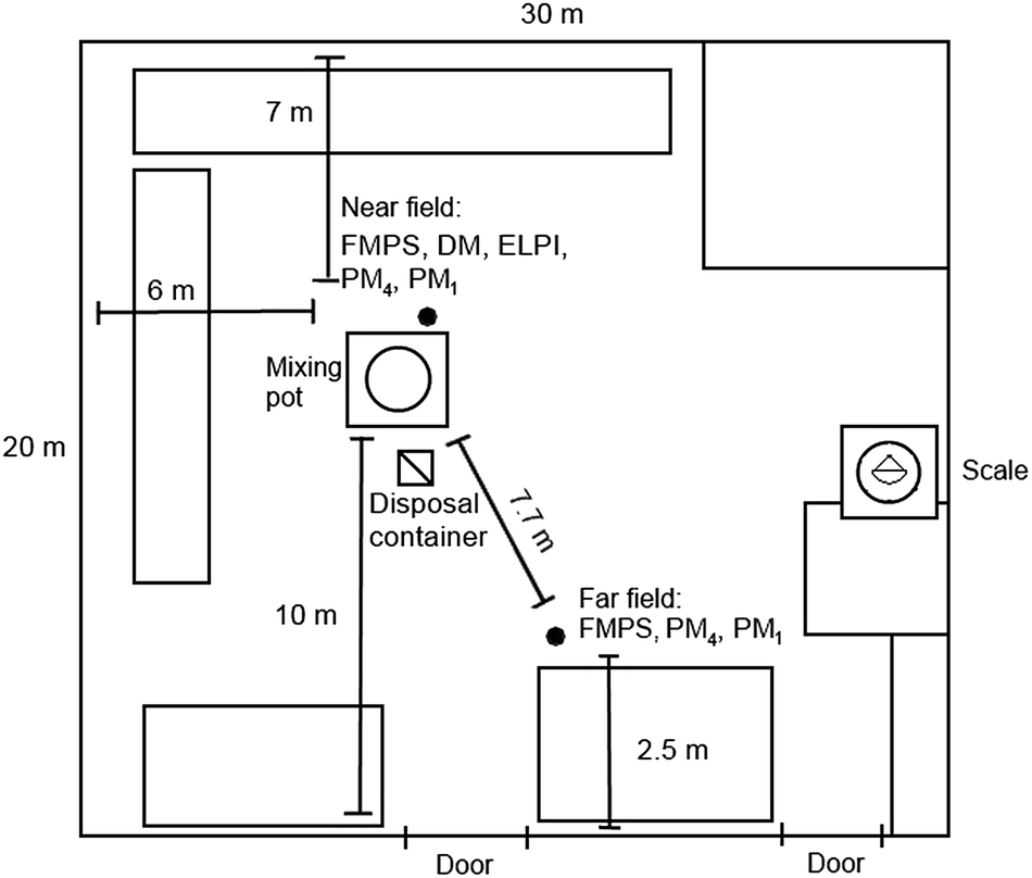 | ||
| Fig. 1 Layout of the mixing room. | ||
| Product | Formula | CAS-no. | Bulk density, [kg m−3] | D 50, [μm] | OEL, [mg m−3] | GK2.69 | ELPI | FMPS | ||||
|---|---|---|---|---|---|---|---|---|---|---|---|---|
| DIma, [mg kg−1] (ART multiplier) | DIN, [× 108 kg−1] | UFP, [%] | Resp., [%] | DIN, [× 108 kg−1] | UFP, [%] | Resp., [%] | ||||||
| a Mean ± standard deviation and classification of the ART multipliers are described by Fransman et al.8 b Inorganic respirable dust. | ||||||||||||
| RD3 (Sachtleben Pigment GmbH, Pori, Finland) | TiO2 (93%), Al2O3, ZrO2, organic | 13463-67-7 | 800 | 0.22 | 6 | 5.3 ± 2.3 (0.03) | 1.6 | 66.1 | 99.0 | 0.8 | 64.0 | 99.7 |
| Micro Mica W1 (Norwegian Talc AS, Knarrevik, Norway) | KAI2(AlSi3O10) (OH)2 | 12001-26-2 | — | 9 | 5b | 22.4 ± 5.5 (0.1) | 7.7 | 20.3 | 97.7 | 10.7 | 39.0 | 99.6 |
| TR92 (Huntsman, Hartlepool, UK) | TiO2 (94%), Al2O3, ZrO2 | 13463-67-7 | 1200 (tamped) | 0.24 | 6 | 1.6 ± 1.0 (0.01) | 0.6 | 76.9 | 99.4 | 0.1 | 52.5 | 99.6 |
| Satin Tone W (Whitetex; BASF Florham Park, NJ, U.S.A.) | Al2Si2O5(OH)4 | 92704-41-1 | 256 | 1.4 | 2 | 2.4 ± 5.5 (0.01) | 0.7 | 75.4 | 99.1 | 0.7 | 83.3 | 99.8 |
| Microdol Norwegian Talc AS, Knarrevik, Norway) | CaMg(CO3)2 | 16389-88-1 | 700 | 7.5 | 5b | 12.1 ± 1.2 (0.03) | 0.4 | 16.0 | 97.6 | 0.8 | 73.4 | 99.8 |
| R-KB-6 (Sachtleben Pigment GmbH, Krefeld, Germany) | TiO2 (94%), Al2O3, ZrO2 | 13463-67-7, 21645-51-2 | 500 | 0.37 | 6 | 9.9 ± 1.1 (0.03) | 2.5 | 35.9 | 98.5 | 1.5 | 32.2 | 99.6 |
| Plastorit, Talc (Imerys Talc, Andritz, Austria) | SiO2 (33%), chlorite (33%), mica (33%) | 1318-59-8, 12001-26-2, 14808-60-7 | 860 | — | 5b | 20.3 ± 7.0 (0.1) | 3.6 | 25.6 | 97.1 | 6.5 | 21.5 | 99.6 |
| Diafil 530 (Imerys, San Jose, CA, U.S.A.) | SiO2 (93%) | 61790-53-2 | 470 | 11 | 5b | 108.9 ± 11.1 (0.3) | 9.8 | 8.8 | 95.6 | 7.3 | 19.0 | 99.5 |
Workplace measurements
Particle concentrations were measured with stationary instruments at a height of 170 cm. A near field (NF) measurement location was always approximately 0.5 m from the mixing station and 1 m from the worker. A far field (FF) measurement location was 7.7 m from the mixing station (Fig. 1).The NF and FF mobility particle size distributions were measured from 5.6 nm to 560 nm in 1 s intervals with two Fast Mobility Particle Sizers (FMPS, TSI model 3091, TSI Inc., Shoreview, MN, USA). The NF optical particle size distributions were measured from 250 nm to 30 μm in 6 s intervals with Grimm Dust Monitors (DM, Grimm model 1.109, Grimm Aerosoltechnik, Ainring, Germany). The NF aerodynamic particle size distributions were measured from 6 nm to 10 μm in 1 s intervals with an Electrical Low Pressure Impactor (ELPI, Dekati model ELPI+, Dekati Ltd., Tampere, Finland).
Gravimetric samples of respirable particulate matter were collected from the NF, FF, breathing zone (personal sampler), and outdoor air. The respirable fraction has a D50 cut size of 4 μm and is defined in detail by the European Committee for Standardization30 and the ACGIH.31 Samples were collected on 37 mm Teflon filters with a 0.8 μm pore size (Millipore, Billerica, MA, USA) using BGI Model SCC1.062 (Qs = 1.05 L min−1) and BGI Model GK2,69 (Qs = 4.2 L min−1)32 Triplex cyclones (BGI Inc., Waltham, MA, USA). Three blind filters were used as controls to correct for handling and environmental factors. Filter weighing was completed in a climate controlled weighing room (50% relative humidity and 22 °C) after at least 24 hour acclimatization.
For the purpose of single particle analysis with electron microscopes, particles were collected on Ni-TEM grids and carbon substrates using a micro-inertial impactor equipped with two stages, covering a size range of 50 nm to 3.5 μm projected area diameter. For further description of sampling see Kandlera et al.33 and Lieke et al.34 and their references. Particle samples that correspond to NF were sampled for a short time (minutes) during pouring processes, and reference samples were taken outdoors, where background conditions are considered.
The mixing room relative humidity and temperature were monitored by using Gemini TinytagPlus Data Loggers (Gemini Data Loggers Ltd, West Sussex, UK).
Unit conversion from particle number to mass
Mass concentrations were calculated from particle number size distributions measured by using the DM and ELPI by assuming spherical particles. The respirable mass concentration was calculated by multiplying the mass distributions with the simplified respirable fraction penetration efficiency according to Hinds.35 The particle average density was selected so that the DM respirable mass concentration corresponds to the average mass concentration measured by the gravimetric samplers (Table 2) over the respective time period. This results at a density of 1.7 g cm−3 while bulk densities varied from 0.256 to 1.2 g cm−3 (Table 1).| Day 1 | Day 2 | |||
|---|---|---|---|---|
| Instrument/method | m, (μg m−3) | N, (cm−3) | m, (μg m−3) | N, (cm−3) |
| a a–d Values below the detection limit which were for a 177, b 31, c 109, and d 100 μg m−3, e brackets show the 75th percentile inter-quartile confidence interval. | ||||
| Near field | ||||
| SCC1.1062 | 101.0a | — | 125.0 | — |
| GK2.69 | 173.0 | — | 19.0b | — |
| DM | 99.1 | 210 | 186.3 | 230 |
| ELPI | 253.0 | 11![[thin space (1/6-em)]](https://www.rsc.org/images/entities/char_2009.gif) 800 800 |
170.9 | 8300 |
| FMPS | 6.6 | 6500 | 5.6 | 4980 |
| The NF/FF model | 86.4 | 420 | 145.9 | 230 |
| The ARTe | 770 (410–1500) | — | 550 (290–1100) | — |
|
||||
| Far field | ||||
| SCC1.1062 | 0.02c | — | 0.05d | — |
| FMPS | 6.1 | 6140 | 5.3 | 4520 |
| The NF/FF model | 5.3 | 24 | 9.3 | 15 |
|
||||
| Personal sampling | ||||
| SCC1.1062 | 515.0 | — | 493.0 | — |
Electron microscopy
Particles were analyzed by means of scanning (SEM) and transmission electron microscopy (TEM), using a FEI ESEM Quanta 200 FEG with an acceleration voltage of 20 kV and a FEI TEM Tecnai T20 G2 (FEI, the Netherlands) operating at 200 kV. Chemical characterization was derived by spot analysis and mapping with energy dispersive X-ray detection (EDS, Oxford Instruments 80 mm2 X-Max SDD detector, Oxford Instruments, UK).Characterization of dustiness indices
Dustiness measurements were performed for Table 1 materials, which were collected during the measurement campaign from the bags. Dustiness indices were determined using the down-scaled EN 15051 dustiness drum and procedures described therein28,29 with a sampling train for the FMPS, ELPI, and Aerodynamic Particle Sizer (APS, model 3321, TSI Inc., Shoreview, MN, USA) particle size distribution measurements. Samples for gravimetric measurements were collected on Teflon filters with the GK2.69 (BGI Inc., Waltham, MA, USA) respirable cyclone (Fig. 2). Here, we do not show results from the APS measurements.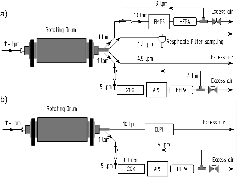 | ||
| Fig. 2 Setups to measure the dustiness index with a small rotating drum using (a) the FMPS and (b) the ELPI. | ||
The drum was ventilated with HEPA-filtered air with a relative humidity of 50% at a rate of 11 L min−1. Prior to each quantitative test, the drum surfaces and sampling lines were “saturated” with dust using 2 g of the powder and rotating it for 60 seconds. After this saturation run, the drum was emptied and 6 g of test material were loaded into the drum for experiments using setup 1 as shown in Fig. 2a. Before the experiment, the background particle concentration was measured for 60 seconds to ensure a particle free test atmosphere. The experiment was then started through 60 second of drum rotation followed by 120 seconds sampling to collect the entire dust cloud. The experiment was then repeated for an additional two times to ensure repeatability. Thereafter an additional testing was performed using setup 2 as shown in Fig. 2b. Each dustiness index was determined as the average of three repeats. The drum and sampling system were thoroughly cleaned between each test material as described by Schneider and Jensen.28
Description of the NF/FF model
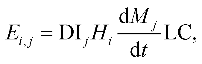
The NF/FF model that was used in this study is described in general by Cherrie et al.36 and in detail by Zhang et al.17 The model assumes that (1) all mass entering the model volume is created at a source inside the NF volume, (2) particles are fully mixed at all times in the NF and FF, (3) there is limited air exchange between NF and FF volumes, and (4) there are no other particle losses than the FF ventilation. In the NF/FF model, the NF volume can be fixed either onto a source (see e.g. Jayjock et al.12 and references therein) or the worker's head which is moving around in the FF volume with an enveloping NF volume.7 Here, the NF was defined as a cube with 2 m sides (VNF = 8 m3) centered on the quadratic opening where the material was poured into the mixing tank, at a height of 1 m from the ground, which was considered to be the main source for particulate matter. Thus, the NF volume covered the worker's breathing zone and the NF instrument inlets during the pouring process. In the ART model, this corresponds to a situation where the worker is within 1 m of the source. One critical parameter in the NF/FF model is the air flow between the NF and FF which is discussed in detail by Zhang et al.17 Our models were made using three different air flow rates between NF and FF, QNF (m3 min−1), which represents minimal (3 m3 min−1), intermediate (10 m3 min−1), and maximal (30 m3 min−1) likely convective airflows as described by Cherrie.37The emission from process i by handling of powder j is described with the potential emission rate Ei,j (units min−1):
 | (1) |
The handling energy factor of the process, Hi, relates the mechanical energy used in the process i to the mechanical energy applied in dustiness index measurement.28 Thus, the handling energy factor of the process equals 1 if the applied mechanical energy equals the energy that was used to measure the dustiness index or has the same effective dispersion effect. If de-agglomeration was complete in the dustiness index measurement, then the handling energy factor is 0 ≤ Hi ≤ 1, otherwise Hi ≥ 0.21 Determinants underlying material dustiness are listed with references by Fransman et al.8 and the potential emission source modifying factors are described by Van Tongeren et al.38
In this study, pouring-process-specific handling energy factors were defined by adjusting the NF/FF pouring-process-specific concentration levels at similar concentration levels measured by the DM.
ART model parameterization
In the ART model, the handling energy factor multiplier depends on the mass-flow (varies from 0.03 to 30; here 3 corresponding to a transfer rate of 10–100 kg min−1), handling carefulness (0.3 or 1; here 1 corresponding routine transfer), and drop height (1 or 3; here 3 corresponding >0.5 m drop height).8 Other modifying factors are related to powder properties, such as the dustiness index for which the corresponding ART multipliers are listed in Table 1. The powder moisture content was assumed to be 0% in this study, which has a multiplier of 1.8 The dispersion multiplier would be close to 0.7 which in the ART model is used for a 3000 m3 room with 3 air exchanges per hour. In the SB pouring there was no localized control and hence we used a multiplier of 1 whereas low specification containment by the discharge cone was present in the BB pouring, leading us to use a localized control multiplier of 0.1. The ART concentrations, which were calculated according to Fransman et al.,8 were corrected by using a calibration factor of ln(α) = 3.01 as defined by Schinkel et al.9 and dustiness multipliers given in Table 1.Results
Dustiness measurements
Table 1 shows measured dustiness indices in units of mass and particle number. By following the EN 15051 standard classification,29 Diafil amorphous silica was ranked in dustiness as Moderate; Microdol, Pastorit, and Micro Mica were ranked as Low; and Satin Tone and titanium dioxides RD3, TR92, and R-KB-6 were ranked as Very Low.Currently there are no ranking levels for dustiness in particle number. According to the ELPI, in particle number, Diafil emitted 9.8 × 10⁸ kg−1, Microdol, Pastorit, and Micro Mica emitted 0.4 × 10⁸ to 7.7 × 10⁸ kg−1, and Satin Tone and titanium dioxides RD3, TR92, and R-KB-6 emitted 0.6 × 10⁸ to 2.5 × 10⁸ kg−1. According to the ELPI, nearly all particles (>95.6%) were respirable particles, and 8.8 to 76.9% were ultrafine particles (Table 1). The correlation between the ELPI and FMPS dustiness index measurements was 0.88.
Concentrations
In the workplace, relative humidities and temperatures measured at the NF and FF varied between 40 to 55% and 19.5 to 23.5 °C. Fig. 3 shows that powder pouring increased the NF concentrations of particles in between 0.1 and 20 μm. Fig. 4 shows that the respirable mass distributions were similar for both days when averaged over NF gravimetric sampling periods shown in Fig. 5. The averaged mass distribution mode was 2.8 ± 0.3 μm with a geometric standard deviation of 2.16 ± 0.12 (95% of the mass was between 0.6 and 13.1 μm).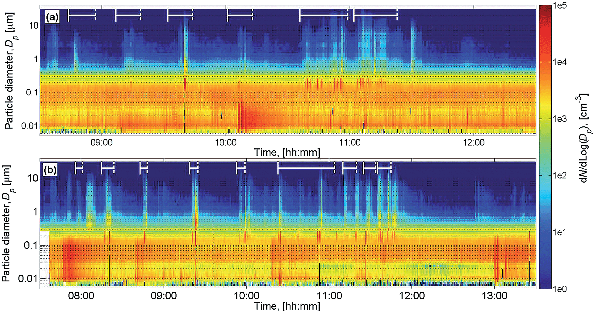 | ||
| Fig. 3 NF particle size distribution time series for (a) day 1 and (b) day 2. Material pouring time intervals are shown with horizontal white lines. | ||
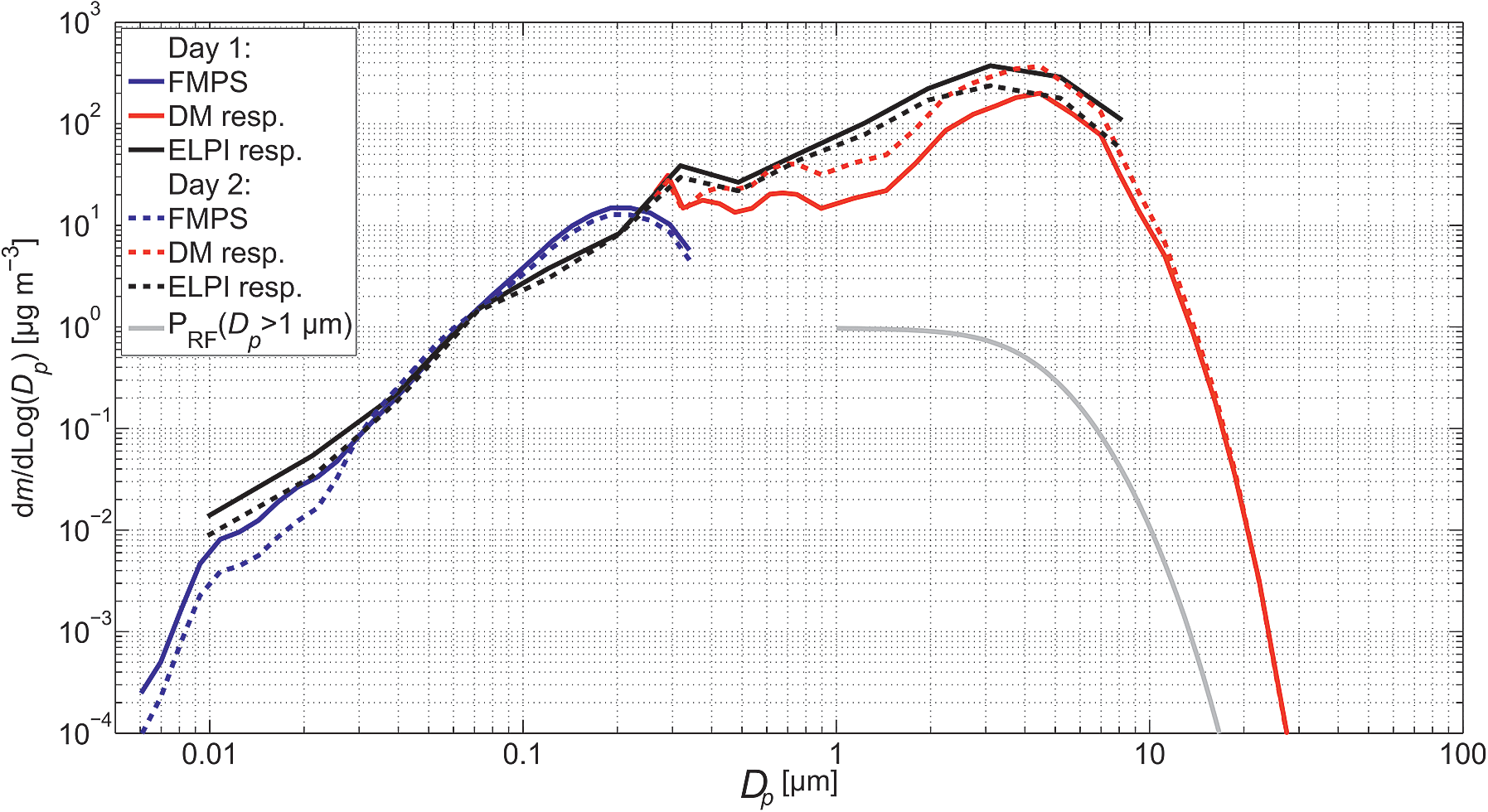 | ||
| Fig. 4 Respirable mass distribution averages calculated over the gravimetric NF sampling period and PRF shows the simplified respirable fraction penetration efficiency for particles over 1 μm in diameter. | ||
 | ||
| Fig. 5 NF respirable mass concentration time series for (a) day 1 and (b) day 2. Gravimetrical personal and NF samplers show the mean mass concentration level defined for the sampling time interval. | ||
The NF mass concentrations were above the detection limit only for GK2.69 during day 1 and SCC1.062 during day 2 (Table 2) where the average mass concentration was 149 μg m−3. The average respirable mass concentration for the respective measurement periods estimated from converting the DM and ELPI data was 142.7 μg m−3 and 219.7 μg m−3, respectively. Personal respirable dust exposure levels sampled from the worker breathing zone was 5.1 and 3.94 times higher than the respective NF concentrations (Table 2). Outdoor respirable mass concentrations were clearly below detection limits.
Fig. 5 shows how powder pouring clearly elevates respirable mass concentrations measured with the ELPI and DM but do not elevate significantly the NF number concentrations as measured by the ELPI or FMPS (Fig. 6). The particle number concentration increase was difficult to detect because the background particle number concentration was high as compared to the process particle emissions. Thus, the NF/FF concentration ratios measured by the FMPSs were nearly the same (1.06 and 1.10 for days 1 and 2, respectively; Table 2).
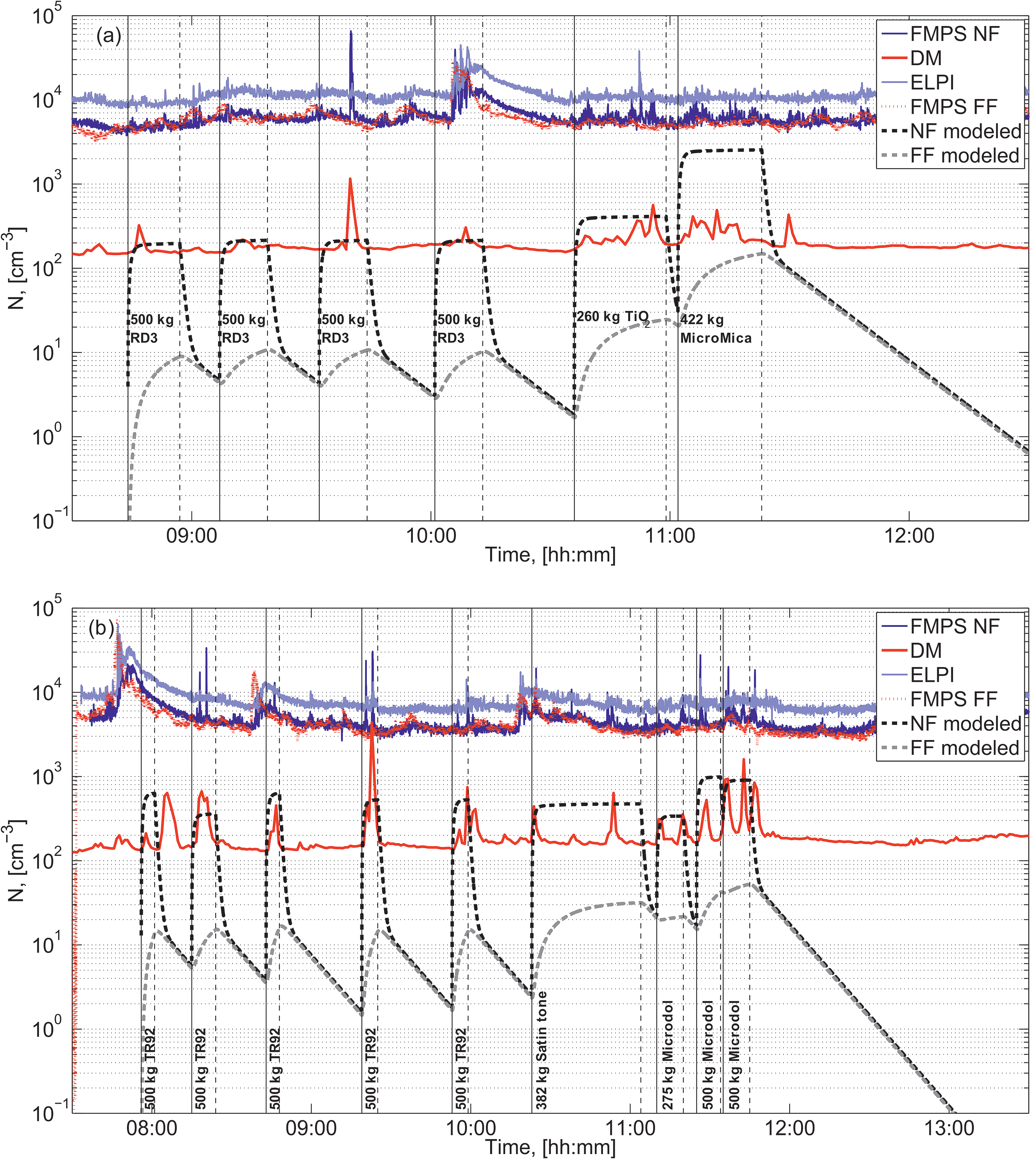 | ||
| Fig. 6 NF and FF particle number concentration time series for (a) day 1 and (b) day 2. The NF/FF model takes into account only process particle emissions while measurements include both process particles and background particles. | ||
Microscopy analysis
Particles on the samples collected for electron microscopy were mainly mineral pigment/filler particles. Even though the sampling time spanned more than one process in most cases, the single particles can be allocated to the powders as described by the manufacturer data sheets. However, most particles appear to be agglomerated and coatings are observed on many of them. Generally coatings were assumed to be the inorganic/organic as specified in the technical data sheets (Table 1) usually a few tens of nanometers thick on single particles. Thicker layers of coatings appeared on heavily agglomerated particles collected during the pouring process (Fig. 7e). While the primary particle sizes as measured from microscopy images (data not shown) were usually close to the D50 indicated by the manufacturer data sheets, the agglomerate size might vary. Fig. 7 shows examples of pigment/filler particles (a, b, and c) sampled from the NF and soot (d) sampled outdoors. Internally mixed agglomerates and thick-coated particles were found only on those samples corresponding to the NF measurements.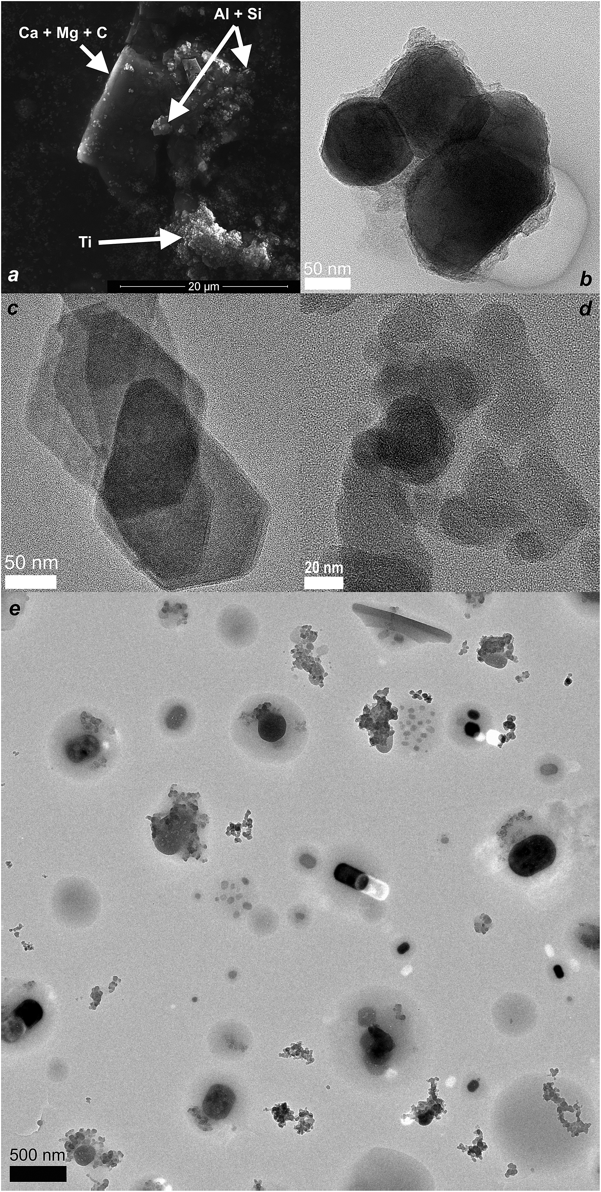 | ||
| Fig. 7 Micrographs of collected particles: (a) SE image showing dolomite (Ca + Mg + C), mica (Al + Si) and TiO2 (Ti) particles and HRTEM images of (b) agglomerated TiO2, (c) mica sheets, (d) soot, and (e) overview of mixed particles. | ||
The TEM samples also suggest that soot was present in the background in high abundance. Soot was found in a high number of individual agglomerates (e.g. 6 soot agglomerates per 16 pigment/filler particles in respirable fraction) on the samples corresponding to the NF. TEM high resolution (Fig. 7d) on individual soot particles revealed the typical onion shell-like structure in primary particles of 20 to 50 nm in diameter.
NF/FF modeling
The handling energy factors (Hi) were defined separately for each pouring process by adjusting Hi so that modeled and measured mass concentrations covered from the DM measurements were similar during pouring. The DM was selected as the reference instrument because 95% of the respirable mass emitted during pouring was between 0.6 and 13.1 μm which is the range covered by the DM. The average mass concentration ratios with standard deviations calculated for modeled and measured concentrations during pouring events using different NF ventilation rates were mNF/mDM = 1.00 ± 0.02 and mNF/mELPI = 1.6 ± 1.1. This means that the NF/FF modelled concentrations were very similar to the values measured by the DM but differ quite much from the ELPI mass concentrations when using the adjusted handling energy factors shown in Table 3.| Pouring process | n | H i , (QNF = 3 m3 min−1) | H i , (QNF = 10 m3 min−1) | H i , (QNF = 30 m3 min−1) | m DM, (μg m−3) | N DM, (cm−3) | Fransman et al.,8 (mg m−3) |
|---|---|---|---|---|---|---|---|
| a Brackets show the number of poured SBs during the pouring process. | |||||||
| BB RD3 | 4 | 0.86 | 2.35 | 6.30 | 82.7 | 210 | 0.38 |
| BB TR92 | 5 | 8.30 | 18.60 | 49.00 | 364.0 | 420 | 0.128 |
| BB Microdol | 2 | 2.60 | 7.40 | 19.70 | 767.8 | 400 | 0.38 |
| SB RD3 | 1 (10) | 0.26 | 0.78 | 2.12 | 167.1 | 250 | 3.8 |
| SB Micro Mica | 1 (17) | 0.06 | 0.19 | 0.51 | 305.4 | 280 | 12.8 |
| SB Satin Tone | 1 (16) | 0.36 | 1.09 | 2.93 | 97.6 | 190 | 1.3 |
| SB Microdol | 1 (11) | 0.09 | 0.23 | 0.60 | 245.2 | 220 | 3.8 |
Table 2 shows mass and number concentrations predicted by the NF/FF model using the adjusted Hi multipliers defined with QNF = 10 m3 min−1. The NF/FF model mass concentration was 0.5 times lower and 1.2 times higher than gravimetric measurements for days 1 and 2, respectively (Table 2). If gravitational settling was taken into account in the NF volume as in Cherrie et al.,36 the NF and FF concentrations would decrease approximately 0.3% when using settling velocities for 2.8 μm particles as defined by Schneider et al.39
The average mass concentrations predicted by the ART for days 1 and 2 were approximately 4.4 times higher for both days than gravimetric measurements (Table 2; ESI† Reports 1 and 2 show the ART reports for days 1 and 2, respectively). For individual pouring activities, the ART predicted average mass concentrations with a 75th percentile inter-quartile confidence interval of 900 (470–1700) μg m−3 for BB pouring and 2700 (1400–5100) μg m−3 for SB pouring (ESI† Reports 3 to 10 show the ART reports for each pouring). Table 3 shows individual pouring time concentrations calculated according to Fransman et al.8
Discussion
Dustiness indices of powders used for paint manufacturing were mainly Low or Very Low (Table 1). Diafil was found to have moderate dustiness even-though the primary particle median size was 11 μm. Here we did not find any correlation between the primary particle size given by the manufacturer and the dustiness index either in units of particle number or mass (Table 1). Similar findings were made by Evans et al.40 for fine and nanoscale powders.The NF respirable mass concentrations at the mixing station were 2.9 and 3.9 times lower than personal exposure measured at the breathing zone for days 1 and 2, respectively (Table 2). This means that the inlets of the NF instruments underestimated personal exposure concentrations, or alternatively, the worker was exposed to particles mainly outside of the NF volume. Such exposure may occur for example when empty bags were folded outside of the NF volume and approximately 3 m from FF instruments so that the emission was not detected by instruments. It has also previously been reported that personal exposure levels exceed the values determined by stationary measurements.41 Personal exposure levels were clearly below occupational exposure limits, which varied from 2 to 6 mg m−3 for the respirable fraction (Table 1), even if the workers' use of respirators was not taken into account. However, especially PM exposure is known to relate to a wide range of occupational diseases as shown e.g. by Omland et al.42 Also, exposure to urban fine particulate matter <2.5 μm (PM2.5) is recognized to be globally the 9th most powerful risk factor for burden of disease.43 Thus, it is recommended to minimize the exposure by using local exhaust ventilation systems, enclose the emission source, or wear respirators in case such engineered controls are not available.
Source emission characteristics are affected by several modifying factors which are discussed in general by Cherrie and Schneider44 and protection factors of localized controls by Fransman et al.45 Modifying factor multipliers that are used in the ART model are shown by Fransman et al.7,8 and McDonnell et al.13 Here the SB pouring was an open process (LC was 1) and in the BB pouring the discharge cone in the big bag was assumed to be a low specification containment (LC was 0.1). In this case, pouring processes were performed in the same company and by the same person under similar environmental conditions. Thus, it is reasonable to assume that the pouring process repeatability was good and modifying factors should remain similar. The handling energy factor multiplier for pouring from over 0.5 m is 3 and the modifying factor multiplier for a transfer rate between 10 and 100 kg min−1 is 3.8 Thus, the modifying factor multiplier for both pouring processes is 9.
However, assuming an average aerosol density of 1.7 g cm−3, it was found that the handling energy factor varied for HBB from 2.35 to 18.60 and for HSB from 0.19 to 1.09 when QNF was 10 m3 min−1 (Table 3). The NF air flow rate QNF reduces or increases the handling energy factor approximately 2.7 times if QNF is either 3 or 30 m3 min−1 (Table 3). In this study, it was possible to assess only the handling energy factor range because QNF was not measured and ventilation QFF was not well known. However, in this study, QFF does not have a high effect on results. For example, if air exchange ratios would be 2 or 8 h−1 (i.e. 5 ± 3 h−1), the NF/FF model NF concentration during day 1 would be 91.3 or 84.6 μg m−3, respectively. Thus, the QFF has only a minor effect when the handling energy factor is adjusted from the NF concentrations.
A critical finding in this study was the variation of the handling energy factor between similar processes and systematic difference between HBB and HSB. Depending on QNF, HBB was from 6 to 49 times higher than HSB even though they should be at a similar level according to previously assigned modifying factors. Also HSB was clearly below 9 even at maximal likely convective air flow (Table 3). Critical parameters for scaling by the modifying factors are the values defined for the handling energy factors, drop-heights and definition of localized controls. These immediately cause a significant offset in scaling. In addition, gravimetric mass samples consist of background particles (e.g. soot) and pigment/filler particles with vapours condensed on them (Fig. 7a). The amount of condensed vapor may vary depending on the particle type and cause a relative error in pigment/filler mass concentration assessment. However, none of these parameters can explain the high variability observed in the derived handling energy factors. It is obvious that the observed variability is partly related to measurement uncertainties and a low amount of pouring repeats but those factors alone cannot explain such high and systematic differences between the two types of pouring.
An important issue in the estimation of the PM emission source strength from the dustiness index is how well forces applied to the powder in the specific dustiness measurement correspond to forces in occupational powder handling.21,24,46 Bach et al.24 discussed in detail the forces acting on the material during the dustiness measurement process and showed their relative influence on the two reference methods according to the EN 15051 (rotating drum and continuous drop)29 and two other methods (UNC Dustiness Tester and single drop). They concluded that material dustiness depends on the interacting forces used in the test procedure and a testing method should be selected so that it reproduces energy used in the corresponding material handling. This is also emphasized in the EN 15051 and one of the key topics in the development of the new dustiness standard under development for nanomaterials.47,48 The dustiness index characterized with the continuous drop method might provide better correlation with both the pouring processes and reduce deviation between handling energy factors that were assigned here.
Another issue is how well the dustiness index, defined by the EN 15051, is scalable for large mass flows. Higher mass flow is assumed to increase emissions but this may not always be true because the product to air interface may decrease.49 However, here it looks as if material pouring through the big bag discharge cone increased the handling energy factor. Therefore, one might consider that careful powder pouring from bags or pouring from the edge into a semi-closed mixer would not necessarily result in a higher exposure risk when assessed from the stationary measurements. The situation, however, may be very different, if the exposure is measured in the worker's inhalation zone as personal exposure levels were notably higher than the stationary PM concentrations. This is likely due to the fact that the worker is closer to the source than the stationary measurement station during the powder handling events; especially when handling small bags.
The NF/FF model comparison with the ART is not straightforward because the ART exposure model is using inhalable, and not respirable, fractions as in this study. Calibration multipliers which are defined from occupational hygienic measurements and the interpretation of parameters are not always straightforward. However, individual pouring concentrations were overestimated by methods described by Fransman et al.8 1.5 times in BB pouring and 56 times in SB pouring (Table 3). Subsequently, the work shift exposure including the non-exposure time during day 1 was 2.2 mg m−3 which is nearly 3 times more than the ART estimated (Table 2). Individual pouring concentrations were also overestimated by the ART 4.7 and 28 times, respectively, for BB pouring and SB pouring. In this study, the ART predicts the work shift inhalable concentrations well when compared to the gravimetrically measured NF and personal respirable concentrations. Discrepancy may be caused by differences in the source emission potency calculation methods between the ART and Fransman et al.8 However, this shows that in this case the model in the method by Fransman et al.8 estimates well the NF concentrations for BB pouring but overestimates the NF concentrations during SB pouring.
In the number concentration modeling, we used the same handling energy factors that were characterized from the mass concentration modelings with QNF = 10 m3 min−1 (Table 3). Comparison of the modeled NF values with the measurements is challenging due to high background number concentrations compared to the number concentration increase by pouring processes. However, Fig. 6 shows that the number concentration measured by the DM was below 200 cm−3 when there were no pouring processes and Table 3 shows that during pouring processes, the average number concentrations in the NF varied from 190 to 420 cm−3. Thus the pouring process increased the NF number concentrations roughly up to 200 cm−3 on average, which is less than the average modeled process particle concentration values of 420 cm−3 and 230 cm−3, respectively, for days 1 and 2 (Table 2).
One way to study the modifying factors in the PM source characteristics is to measure and assess particle emission rates from various processes under laboratory conditions and at work-places where environmental conditions and processes are well known. As pointed out by Zhang et al.,17 the air exchange QNF between the NF and FF volumes is one poorly known parameter. The PM dispersion at work places could be studied with flux measurements.50
Emission source characterization should be extended from powder handling to also cover PM emissions from other processes such as ultrafine particle emissions from high energy processes (e.g. Koponen et al.51) and processes where new particle formation may occur (e.g. Nørgaard et al.52). This requires measurement of size and time-resolved process particle concentrations where source emission rates are resolved with indoor aerosol modeling.53,54 There are various source characterization studies made both for consumer products and occupational processes.55–71 Similarly particle sinks can be assessed according to the model by Mølgaard et al.72 made for indoor air cleaners. Some of these scenarios could potentially be covered with exposure assessment tools such as the ConsExpo REACH tool, but this tool may not be applicable to larger scale industrial exposure scenarios.
Conclusions
The development of aerosol modeling for exposure assessment is compulsory in order to fulfil the REACH regulation. Several quantitative exposure assessment tools are available. However, their performance for particulate matter exposure assessment has not been previously evaluated in detail by comparing modeling with the measured exposure in a real work environment.In this study, we evaluated the performance of the NF/FF model using a source emission strength that was based on the rotating drum dustiness test. We showed that particle emission rates for a powder pouring process from big bags and small bags were not well predicted when using the dustiness index. We suggest that emission source characterization based on the dustiness index should be further studied by defining process-specific emission rates with indoor aerosol models in well-controlled environments and processes which are then linked to dustiness indices determined using different types of dustiness tests.
We propose that a generalized particle emission rate term (units e.g. in particles min−1, μm min−1, or mg min−1) should be implemented in REACH inhalation exposure assessment tools. Such emission terms could be defined also for sources emitting ultrafine particles and exposure analysis could thereby be assessed also in other units than mass, which could also be useful for the assessment of the biologically effective dose.
Acknowledgements
The research leading to these results has received funding from the European Community's Seventh Framework Programme (FP7/2007–2013) under NanoValid (grant agreement no. 263147) and this work was supported by a grant from the Danish Centre for Nanosafety (grant agreement no. 20110092173/3) by the Danish Working Environment Research Fund.Notes and references
- European Union Regulation (EC) No 1907/2006 of the European Parliament and of the Council of 18 December 2006 concerning the Registration, Evaluation, Authorisation and Restriction of Chemicals (REACH). Off J Eur Commun 2006; L136: 3–280, http://www.reach-compliance.eu/english/legislation/docs/launchers/.
- T. L. Ogden, Ann. Occup. Hyg., 2009, 53, 775–777 CrossRef CAS PubMed.
- E. Hofstetter, J. W. Spencer, K. Hiteshew, M. Coutu and M. Nealley, Ann. Occup. Hyg., 2013, 57, 210–220 CrossRef CAS PubMed.
- ECETOC targeted risk assessment, Technical Report no. 93, European Centre for Ecotoxicology and Toxicology of Chemicals, Belgium, Brussels, 2004 Search PubMed.
- H. Marquart, H. Heussen, M. Le Feber, D. Noy, E. Tielemans, J. Schinkel, J. West and V. Der Schaaf, Ann. Occup. Hyg., 2008, 52, 429–441 CrossRef PubMed.
- M. Tischer, S. Bredendiek-Kämper, U. Poppek and R. Packroff, Ann. Occup. Hyg., 2009, 53, 449–462 CrossRef CAS PubMed.
- W. Fransman, J. W. Cherrie, M. van Tongeren, T. Schneider, M. Tischer, J. Schinkel, H. Marquart, N. Warren, H. Kromhout and E. Tielemans, TNO report V9009, Zeist, 2010 Search PubMed.
- W. Fransman, M. Van Tongeren, J. W. Cherrie, M. Tischer, T. Schneider, J. Schinkel, H. Kromhout, N. Warren, H. Goede and E. Tielemans, Ann. Occup. Hyg., 2011, 55, 957–979 CrossRef CAS PubMed.
- J. Schinkel, N. Warren, W. Fransman, M. Van Tongeren, P. McDonnell, E. Voogd, J. W. Cherrie, M. Tischer, H. Kromhout and E. Tielemans, J. Environ. Monit., 2011, 13, 1374 RSC.
- J. Schinkel, P. Ritchie, H. Goede, W. Fransman, M. Van Tongeren, J. W. Cherrie, E. Tielemans, H. Kromhout and N. Warren, Ann. Occup. Hyg., 2013, 57, 717–727 CrossRef CAS PubMed.
- E. Tielemans, N. Warren, W. Fransman, M. Van Tongeren, K. McNally, M. Tischer, P. Ritchie, H. Kromhout, J. Schinkel, T. Schneider and J. W. Cherrie, Ann. Occup. Hyg., 2011, 55, 979–956 CrossRef PubMed.
- M. A. Jayjock, T. Armstrong and M. Taylor, J. Occup. Environ. Hyg., 2011, 8, D114–D122 CrossRef PubMed.
- P. E. McDonnell, J. M. Schinkel, M. A. Coggins, W. Fransman, H. Kromhout, J. W. Cherrie and E. L. Tielemans, J. Environ. Monit., 2011, 13, 1597–1606 RSC.
- C. B. Keil and M. Nicas, AIHA J., 2003, 64, 445–454 CrossRef CAS.
- J. W. Spencer and M. J. Plisko, J. Occup. Environ. Hyg., 2007, 4, 253–259 CrossRef CAS PubMed.
- M. Nicas and J. Neuhaus, J. Occup. Environ. Hyg., 2008, 5, 599–608 CrossRef CAS PubMed.
- Y. Zhang, S. Banerjee, R. Yang, C. Lungu and G. Ramachandran, Ann. Occup. Hyg., 2009, 53, 409–424 CrossRef CAS PubMed.
- K. Y. K. Chung and G. J. Burdett, Ann. Occup. Hyg., 1994, 38, 945–949 CrossRef CAS.
- J. H. Vincent, in Aerosol Science for Industrial Hygienists, ISBN-0-08-042029-X, Pergamon/Elsevier, Oxford, UK, 1995 Search PubMed.
- N. O. Breum, Ann. Occup. Hyg., 1999, 43, 557–566 CrossRef CAS.
- G. Lidén, Ann. Occup. Hyg., 2006, 50, 437–439 CrossRef PubMed.
- D. H. Brouwer, I. H. M. Links, S. A. F. De Vreede and Y. Christopher, Ann. Occup. Hyg., 2006, 50, 445–452 CrossRef CAS PubMed.
- S. Bach, Ann. Occup. Hyg., 2008, 52, 717–725 CrossRef PubMed.
- S. Bach, U. Eickmann and E. Schmidt, Ann. Occup. Hyg., 2013, 57, 1078–1086 CrossRef CAS PubMed.
- C. Cowherd, M. A. Grelinger and K. F. Wong, Am. Ind. Hyg. Assoc. J., 1989, 50, 131–138 CrossRef.
- W. A. Heitbrink, W. F. Todd and T. J. Fischbach, Appl. Ind. Hyg., 1989, 4, 12–16 CrossRef CAS.
- W. A. Heitbrink, W. F. Todd, T. C. Cooper and D. M. O'Brien, Am. Ind. Hyg. Assoc. J., 1990, 51, 217–223 CrossRef CAS PubMed.
- T. Schneider and K. A. Jensen, Ann. Occup. Hyg., 2008, 52, 23–34 CrossRef CAS PubMed.
- European Standardisation Institute EN 15051, Workplace atmospheres—Measurement of the dustiness of bulk materials—Requirements and reference test methods German version, Beuth Verlag, Berlin, 2011 Search PubMed.
- European Committee for Standardization (CEN), Workplace atmospheres-size fraction definitions for measurement of airborne particles (Report No. BS EN 481), ISBN 0-580-221407, CEN, British Standards Institute, London, England, 1993 Search PubMed.
- American Conference of Governmental Industrial Hygienis (ACGIH): TLVs and BEIs: Based on the documentation of the threshold limit values for chemical substances and physical agents and biological exposure indices. Cincinnati, OH: ACGIH; 2005.
- P. Stacey, T. Lee, A. Thorpe, P. Roberts, G. Frost and M. Harper, Ann. Occup. Hyg., 2014, 58, 512–523 CrossRef CAS PubMed.
- K. Kandlera, N. Benker, U. Bundke, E. Cuevas, M. Ebert, P. Knippertz, S. Rodríguez, L. Schültz and S. Weinbruch, Atmos. Environ., 2007, 41, 8058–8074 CrossRef PubMed.
- K. I. Lieke, T. Rosenrn, J. Pedersen, D. Larsson, J. Kling, K. Fuglsang and M. Bilde, Aerosol Sci. Technol., 2013, 47, 1038–1046 CrossRef CAS.
- W. C. Hinds, in Aerosol Technology: Properties, Behavior, and Measurement of Airborne Particles, ed. W.C. Hinds, John Wiley & Sons Inc., New York, NY, USA, 2nd edn., 1999; ch. 11, pp. 233–259 Search PubMed.
- J. W. Cherrie, L. Maccalman, W. Fransman, E. Tielemans, M. Tischer and M. Van Tongeren, Ann. Occup. Hyg., 2011, 55, 1006–1015 CrossRef CAS PubMed.
- J. W. Cherrie, Appl. Occup. Environ. Hyg., 1999, 14, 539–546 CrossRef CAS PubMed.
- M. Van Tongeren, W. Fransman, S. Spankie, M. Tischer, D. Brouwer, J. Schinkel, J. W. Cherrie and E. Tielemans, Ann. Occup. Hyg., 2011, 55, 980–988 CrossRef CAS PubMed.
- T. Schneider, J. Kildesø and N. O. Breum, Build Environ., 1999, 23, s83–s95 Search PubMed.
- D. E. Evans, L. A. Turkevich, C. T. Roettgers, G. J. Deye and P. A. Baron, Ann. Occup. Hyg., 2013, 57, 261–277 CrossRef CAS PubMed.
- C. Asbach, O. Aguerre, C. Bressot, D. H. Brouwer, U. Gommel, B. Gorbunov, O. Le Bihan, K. A. Jensen, H. Kaminski, M. Keller, I. K. Koponen, T. A. J. Kuhlbusch, A. Lecloux, M. Morgeneyer, B. Stahlmecke and A. M. Todea, in HANDBOOK of NANOSAFETY, Elsevier Inc, 2014, ch 7, pp. 223–278, DOI:10.1016/B978-0-12-416604-2.00001-9.
- Ø. Omland, E. T. Würtz, T. B. Aasen, P. Blanc, J. Brisman, M. R. Miller, O. F. Pedersen, V. Schlünssen, T. Sigsgaard, C. S. Ulrik and S. Viskum, Scand. J. Work, Environ. Health, 2014, 40, 19–35 Search PubMed.
- S. S. Lim, T. Vos, A. D. Flaxman, G. Danaei, K. Shibuya and H. Adair-Rohani, et al. , Lancet, 2012, 380, 2224–2260 CrossRef.
- J. W. Cherrie and T. Schneider, Ann. Occup. Hyg., 1999, 43, 235–245 CrossRef CAS.
- W. Fransman, J. Schinkel, T. Meijster, J. Van Hemmen, E. Tielemans and H. Goede, Ann. Occup. Hyg., 2008, 52, 567–575 CrossRef PubMed.
- D. Dahmann and C. Monz, Gefahrstoffe – Reinhalt. Luft, 2011, 71, 481–487 CAS.
- O. Witschger, D. Brouwer, K. A. Jensen, E. Jankowska, D. Dahmann, G. Burdett and D. Bard, NanOEH, 6th International Symposium on Nanotechnology, Occupational and Environmental Health, Nagoya, Japan, Abstracts, p. 22, October 28–31, 2013, http://square.umin.ac.jp/nanoeh6/docs/NanOEH_program_abstract.pdf Search PubMed.
- O. Witchger, K. A. Jensen, D. Brouwer, I. Tuinman, E. Jankowska, D. Dahmann, G. Burdett and D. Bard, Aerosol Technology, Karlsruhe, 2014, Abstract T230A09. Session APPVI Dustiness and Resuspension: http://www.gaef.de/AT2014/ Search PubMed.
- W. A. Heitbrink, P. A. Baron and K. Willeke, Am. Ind. Hyg. Assoc. J., 1992, 53, 617–624 CrossRef CAS PubMed.
- G. Ripamonti, L. Järvi, B. Mølgaard, T. Hussein, A. Nordbo and K. Hämeri, Tellus, Ser. B, 2013, 65, 19786, DOI:10.1029/10.3402/tellusb.v65i0.19786.
- I. K. Koponen, K. A. Jensen and T. Schneider, J. Exposure Sci. Environ. Epidemiol., 2011, 21, 408–418 CrossRef CAS PubMed.
- A. W. Nørgaard, J. D. Kudal, V. Kofoed-Sørensen, I. K. Koponen and P. Wolkoff, Environ. Int., 2014, 68, 209–218 CrossRef PubMed.
- W. W. Nazaroff, Indoor Air, 2004, 14, 175–183 CrossRef PubMed.
- T. Hussein and M. Kulmala, Water, Air, Soil Pollut., 2008, 8, 23–34 CrossRef.
- W. W. Nazaroff and G. R. Cass, Environ. Sci. Technol., 1989, 23, 157–166 CrossRef CAS.
- S. L. Miller and W. W. Nazaroff, Atmos. Environ., 2001, 35, 2053–2067 CrossRef CAS.
- C. He, L. Morawska, J. Hitchins and D. Gilbert, Atmos. Environ., 2004, 38, 3405–3415 CrossRef CAS PubMed.
- A. Afshari, U. Matson and L. E. Ekberg, Indoor Air, 2005, 15, 141–150 CrossRef CAS PubMed.
- T. Hussein, K. Hämeri, M. S. A. Heikkinen and M. Kulmala, Atmos. Environ., 2005, 39, 3697–3709 CrossRef CAS PubMed.
- T. Hussein, H. Korhonen, E. Herrmann, K. Hämeri, K. Lehtinen and M. Kulmala, Aerosol Sci. Technol., 2005, 39, 1111–1127 CrossRef CAS.
- T. Hussein, T. Glytsos, J. Ondráček, V. Ždímal, K. Hämeri, M. Lazaridis, J. Smolík and M. Kulmala, Atmos. Environ., 2006, 40, 4285–4307 CrossRef CAS PubMed.
- M. D. Sohn, M. G. Apte, R. G. Sextro and A. C. K. Lai, Atmos. Environ., 2007, 41, 1473–1482 CrossRef CAS PubMed.
- E. Géhin, O. Ramalho and S. Kirchner, Atmos. Environ., 2008, 42, 8341–8352 CrossRef PubMed.
- T. Schripp, M. Wensing, E. Uhde, T. Salthammer, C. He and L. Morawska, Environ. Sci. Technol., 2008, 42, 4338–4343 CrossRef CAS.
- T. Schripp, S. J. Mulakampilly, W. Delius, E. Uhde, M. Wensing, T. Salthammer, R. Kreuzig, M. Bahadir, L. Wang and L. Morawska, Gefahrstoffe - Reinhalt. Luft, 2009, 69(3), 71–76 Search PubMed.
- T. Glytsos, J. Ondráček, L. Džumbová, I. Kopanakis and M. Lazaridis, Atmos. Environ., 2010, 44, 1539–1549 CrossRef CAS PubMed.
- A. J. Koivisto, T. Hussein, R. Niemelä, T. Tuomi and K. Hämeri, Atmos. Environ., 2010, 44, 2140–2146 CrossRef CAS PubMed.
- A. J. Koivisto, M. Yu, K. Hämeri and M. Seipenbusch, J. Aerosol Sci., 2012, 47, 58–69 CrossRef CAS PubMed.
- A. J. Koivisto, J. E. Palomäki, A.-K. Viitanen, K. M. Siivola, I. K. Koponen, Y. Mingzhou, T. S. Kanerva, H. Norppa, H. T. Alenius, T. Hussein, K. M. Savolainen and K. J. Hämeri, Int. J. Environ. Res. Public Health, 2014, 11, 5382–5402 CrossRef CAS PubMed.
- R. You, W. Cui, C. Chen and B. Zhao, Aerosol Air Qual. Res., 2013, 13, 911–921 Search PubMed.
- B. E. Boor, M. P. Spilak, R. L. Corsi and A. Novoselac, Indoor Air, 2014 DOI:10.1111/ina.12148.
- B. Mølgaard, A. J. Koivisto, T. Hussein and K. Hämeri, Aerosol Sci. Technol., 2014, 48, 409–417 CrossRef.
- At-Vejledning Stoffer og Materialer – C.0.1 Grænseværdier for stoffer og materialer. Arbejdstilsynet, Denmark, København C 1999, 2007, (accessed on 4 Nov 2014): https://www.retsinformation.dk/Forms/R0710.aspx?id=143596.
Footnote |
| † Electronic supplementary information (ESI) available: Reports of the predicted exposure levels by the Advanced REACH Tool (ART). See DOI: 10.1039/c4em00532e |
| This journal is © The Royal Society of Chemistry 2015 |