Synthesis, X-ray characterization, DFT calculations and Hirshfeld surface analysis studies of carbohydrazone based on Zn(II) complexes†
Ghodrat
Mahmoudi
*a,
Antonio
Bauzá
b,
Antonio
Rodríguez-Diéguez
c,
Piotr
Garczarek
d,
Werner
Kaminsky
e and
Antonio
Frontera
 *b
*b
aDepartment of Chemistry, Faculty of Science, University of Maragheh, P.O. Box 55181-83111, Maragheh, Iran. E-mail: mahmoudi_ghodrat@yahoo.co.uk
bDepartamento de Quimica, Universitat de les IllesBalears, Crta. de Valldemossa km 7.5, 07122 Palma de Mallorca (Baleares), Spain. E-mail: toni.frontera@uib.es
cDepartment of Inorganic Chemistry, University of Granada, Avda Fuentenueva s/n, Granada, 18071, Spain
dFaculty of Chemistry, Wrocław University of Technology, 27 Wybrzeze Wyspiańskiego Street, 50-370 Wrocław, Poland
eX-ray Crystallography Laboratory, University of Washington, USA
First published on 18th November 2015
Abstract
In this manuscript we report the synthesis and X-ray characterization of five complexes of Zn(II) based on a N4O core carbohydrazone ligand (H2L); i.e. {[Zn4(HL)4](CH3OH)4(NO3)4} (1), {[Zn4(HL)4](ClO4)4} (2) {[Zn4(HL)4][Zn(SCN)4](NO3)2} (3) {[Zn(SCN)4](H4L)(CH3OH)2} (4) and {[Zn4(HL)4](NO3)4(H2O)} (5). Structurally characterized tetranuclear Zn(II) complexes, as those reported herein, are scarcely found in the literature. In the crystal structures of several compounds, N–H⋯S hydrogen bonds, anion–π and π–hole interactions are described and analysed by means of density functional theory (DFT) calculations since they play an important role in the construction of three-dimensional supramolecular frameworks. Moreover, the noncovalent interactions have been also analysed using Hirshfeld surface analysis.
1. Introduction
Grid-type supramolecular architectures have been very interesting in the last few years mainly because of the square topology of the metal ions. Such topology of metal ions can generate interesting magnetic, optical or redox properties. Grid-type complexes have potential applications such as molecular-scale sensors, switches and information storage devices in nanotechnology.1 Of the wide variety of grid-forming ligands now known, most incorporate nitrogen donor units forming five-membered chelate rings such as those of the bipyridine or terpyridine form although significant numbers involve oxygen or sulphur-based donor sites, again with five-membered chelate rings preferred for maximum stability.2 Such ligands are far more challenging to synthesise than isotypic ligands incorporating hydrazone or acylhydrazone moieties as metal binding sites. In fact, hydrazone-based ligands are the basis of by far the majority of currently known grid systems,3 this work forming but part of the very extensive and interesting coordination chemistry of such ligands.4 The Thompson's group has made a number of notable contributions to the literature on the subject of metallogrids displaying SMM behaviour, including early works concerning homo- and hetero-metallic grid complexes such as those formed from ligands with the transition metals cobalt, copper and iron,5 as well as, very recently, the [2 × 2] metallogrids formed from ligand H2L (Scheme 1) with Dy(III) , Eu(II) and Ni(II) ions.6 In this work, as a result of our ongoing study of the coordination properties of N-heterocyclic-based polytopic Schiff-base ligands,7 we report the synthesis and X-ray characterization of several tetranuclear Zn(II) complexes with the Schiff base derived from the acetyl pyridine and carbohydrazide precursors, H2L. To the best of our knowledge, few tetranuclear Zn(II) complexes structurally characterized with the N4O core have been described in the literature. In fact, a unique precedent of a molecular square of carbohydrazone in the form of Zn(II) cationic macrocycle was reported in 2007 by Manoj et al.8 The existence as molecular square structure was demonstrated in the solid by X-ray analysis and in solution phase by MALDI mass spectrometry. Carbohydrazone ligands have been also used to synthesize mononuclear Zn complexes.9The theoretical study reported herein is devoted to the analysis of the supramolecular assemblies observed in the solid state of compounds 3 and 4, evaluating the different contributions to molecular recognition and to assign discrete energy values to them. By means of high level DFT calculations and theoretical models we have studied these contributions in the crystal structures that are useful for the understanding of the noncovalent forces and for rationalizing their influence in the crystal packing paying special attention to the π–hole10 and anion–π11 interactions involving the nitrato ligand.
2. Experimental
General procedures: unless stated otherwise, all reactions were conducted by hydrothermal conditions, with the reagents purchased commercially and used without further purification.2.1. Preparation of complexes
 = CH b (oop): 692 (m) and 781 (m); CO st (MeOH): 1025 (m); CH b: 1303(m); O–N–O st: 1380 (s); CCst: 1467 (m); C
![[double bond, length as m-dash]](https://www.rsc.org/images/entities/char_e001.gif) N st: 1546 and 1575 (m); C
N st: 1546 and 1575 (m); C![[double bond, length as m-dash]](https://www.rsc.org/images/entities/char_e001.gif) O st (ligand) 1632; CH st: 2922 (w), NH st and OH st: 3381 (w) cm−1.
O st (ligand) 1632; CH st: 2922 (w), NH st and OH st: 3381 (w) cm−1.
 = CH b (oop): 708 (m) and 780 (m); O–Cl–O st: 1107 (s); CH b: 1295(m); CCst: 1471 (m); C
![[double bond, length as m-dash]](https://www.rsc.org/images/entities/char_e001.gif) N st: 1552 and 1591 (m); C
N st: 1552 and 1591 (m); C![[double bond, length as m-dash]](https://www.rsc.org/images/entities/char_e001.gif) O st (ligand) 1644; CH st: 2911 (w), NH st and OH st: 3448 (w) cm−1.
O st (ligand) 1644; CH st: 2911 (w), NH st and OH st: 3448 (w) cm−1.
![[thin space (1/6-em)]](https://www.rsc.org/images/entities/char_2009.gif) :
:![[thin space (1/6-em)]](https://www.rsc.org/images/entities/char_2009.gif) 2 mole ratio. For 3: (0.16 g, yield 70%), found; C, 41.68; H, 3.13; N, 22.67%. calcd. for C64H60N30O10S4Zn5; C, 41.23 H, 3.24; N, 22.54% IR (selected bands):
2 mole ratio. For 3: (0.16 g, yield 70%), found; C, 41.68; H, 3.13; N, 22.67%. calcd. for C64H60N30O10S4Zn5; C, 41.23 H, 3.24; N, 22.54% IR (selected bands):  = CH b (oop): 694 (m) and 787 (m); CH b: 1307 (m); O–N–O st: 1359 (s); CCst: 1448 (m); C
![[double bond, length as m-dash]](https://www.rsc.org/images/entities/char_e001.gif) N st: 1504 and 1560 (m); C
N st: 1504 and 1560 (m); C![[double bond, length as m-dash]](https://www.rsc.org/images/entities/char_e001.gif) O st (ligand) 1612; S–CN st: 2067 (s); CH st: 3053 (w), NH st and OH st: 3429 (w) cm−1.
O st (ligand) 1612; S–CN st: 2067 (s); CH st: 3053 (w), NH st and OH st: 3429 (w) cm−1.
![[thin space (1/6-em)]](https://www.rsc.org/images/entities/char_2009.gif) :
:![[thin space (1/6-em)]](https://www.rsc.org/images/entities/char_2009.gif) 2 mole ratio of Zn(NO3)2·6H2O and NaSCN were used. For 4: (0.14 g, yield 45%), found; C, 38.68; H, 3.73; N, 21.37%. calcd. for C21H26N10O3S4Zn C, 38.21 H, 3.97; N, 21.22% IR (selected bands):
2 mole ratio of Zn(NO3)2·6H2O and NaSCN were used. For 4: (0.14 g, yield 45%), found; C, 38.68; H, 3.73; N, 21.37%. calcd. for C21H26N10O3S4Zn C, 38.21 H, 3.97; N, 21.22% IR (selected bands):  = CH b (oop): 690 (m) and 779 (m); CO st (MeOH): 1021 (m); CH b: 1297 (m); CCst: 1456 (m); C
![[double bond, length as m-dash]](https://www.rsc.org/images/entities/char_e001.gif) N st: 1619 (m); C
N st: 1619 (m); C![[double bond, length as m-dash]](https://www.rsc.org/images/entities/char_e001.gif) O st (ligand) 1698 (m); S–CN st: 2079 (s); CH st: 3091 (w), NH st and OH st: 3323 (w) cm−1.
O st (ligand) 1698 (m); S–CN st: 2079 (s); CH st: 3091 (w), NH st and OH st: 3323 (w) cm−1.
 = CH b (oop): 693 (m) and 783 (m); CH b: 1308 (m); O–N–O st: 1383 (s); CCst: 1468 (m); C
![[double bond, length as m-dash]](https://www.rsc.org/images/entities/char_e001.gif) N st: 1549 and 1577 (m); C
N st: 1549 and 1577 (m); C![[double bond, length as m-dash]](https://www.rsc.org/images/entities/char_e001.gif) O st (ligand) 1630; CH st: 2924 (w), NH st and OH st: 3448 (w) cm−1.
O st (ligand) 1630; CH st: 2924 (w), NH st and OH st: 3448 (w) cm−1.
2.2. Physical measurements
FT-IR spectra were recorded on a Bruker Tensor 27 spectrometer. Microanalyses were performed using a Heraeus CHN–O–Rapid analyzer.2.3. Single-crystal structure determination
Suitable crystals of 1–5 were mounted on a glass fibre and used for data collection on a Nonius Kappa CCD FR590 area detector equipped with graphite monochromated Mo Kα radiation (λ = 0.71073 Å). Lorentz-polarization and empirical absorption corrections were applied with SADABS.12 The structures were solved by direct methods and refined with full-matrix least-squares calculations on F2 using the program SHELXS97.13 Anisotropic temperature factors were assigned to all atoms except for hydrogen atoms, which are riding their parent atoms with an isotropic temperature factor arbitrarily chosen as 1.2 times that of the respective parent. Final R(F), wR(F2) and goodness of fit agreement factors, details on the data collection and analysis can be found in Table 1. Selected bond lengths and angles are given in Tables S1–S5 (ESI).† CCDC reference numbers for the structures of 1–5 are 1426269–1426273. Copies of the data can be obtained free of charge upon application to CCDC, 12 Union Road, Cambridge CB2 1EZ, U.K. (fax, (+44)1223 336–033; e-mail, deposit@ ccdc.cam.ac.uk).| 1 | 2 | 3 | 4 | 5 | |
|---|---|---|---|---|---|
| a R(F) = ∑||Fo| − |Fc||/∑||Fo|, wR(F2) = [∑w(Fo2 − Fc2)2/∑wF4]½. | |||||
| Empirical formula | C64H76N28O20Zn4 | C66H64Cl4N24O22Zn4 | C64H60N30O10S4Zn5 | C21H26N10O3S4Zn | C60H62N28O17Zn4 |
| Formula weight | 1819.01 | 1942.69 | 1864.51 | 660.13 | 1741.85 |
| Crystal system | tetragonal | Monoclinic | Monoclinic | Triclinic | Tetragonal |
| Space group | P42/n | P21/n | P21/n |
P![[1 with combining macron]](https://www.rsc.org/images/entities/char_0031_0304.gif) |
I41a |
| Wavelength (Å) | 0.71073 | 0.71073 | 0.71073 | 0.71073 | 0.71073 |
| T (K) | 170(2) | 100(2) | 100(2) | 282(2) | 180(2) |
| a (Å) | 13.836(2) | 13.7479(7) | 13.390(2) | 11.4520(3) | 13.9941(9) |
| b (Å) | 13.836(2) | 13.6207(7) | 29.716(4) | 12.1060(4) | 13.9941(9) |
| c (Å) | 19.957(3) | 44.742(2) | 21.716(3) | 13.1380(4) | 35.739(3) |
| α (°) | 90 | 90 | 90 | 115.338(3) | 90 |
| β (°) | 90 | 98.226(2) | 102.996(2) | 99.128(2) | 90 |
| γ (°) | 90 | 90 | 90 | 104.7070(10) | 90 |
| Z | 2 | 4 | 4 | 2 | 4 |
| V (Å3) | 3820.7(1) | 8292.0(7) | 8419.5(19) | 1516.01(8) | 6998.9(9) |
| ρ (g cm−3) | 1.581 | 1.561 | 1.471 | 1.446 | 1.653 |
| μ (mm−1) | 1.331 | 1.357 | 1.573 | 1.127 | 1.451 |
| Unique reflections | 96![[thin space (1/6-em)]](https://www.rsc.org/images/entities/char_2009.gif) 597 597 |
158![[thin space (1/6-em)]](https://www.rsc.org/images/entities/char_2009.gif) 280 280 |
189![[thin space (1/6-em)]](https://www.rsc.org/images/entities/char_2009.gif) 260 260 |
11![[thin space (1/6-em)]](https://www.rsc.org/images/entities/char_2009.gif) 371 371 |
16![[thin space (1/6-em)]](https://www.rsc.org/images/entities/char_2009.gif) 119 119 |
| R(int) | 0.056 | 0.123 | 0.065 | 0.045 | 0.068 |
| GOF on F2 | 1.182 | 1.039 | 1.053 | 0.903 | 0.997 |
| R 1 [I ≥ 2σ(I)]a | 0.043 | 0.072 | 0.045 | 0.042 | 0.048 |
| wR2 [I ≥ 2σ(I)]a | 0.112 | 0.151 | 0.110 | 0.095 | 0.126 |
2.4. Computational details
All calculations were carried out using the TURBOMOLE version 7.0 (ref. 14) using the BP86-D3/def2-TZVP level of theory. To evaluate the interactions in the solid state, we have used the crystallographic coordinates. This procedure and level of theory have been successfully used to evaluate similar interactions.15 To validate this method, we have also compared the results in a selected complex to the MP2/def2-TZVP level of theory (vide infra) and a good agreement has been observed. The interaction energies were computed by calculating the difference between the energies of isolated monomers and their assembly. The interaction energies were corrected for the Basis Set Superposition Error (BSSE) using the counterpoise method.16 The molecular electrostatic potential (MEP) surfaces have been computed at the B3LYP/6–31 + G* level of theory by means of the Spartan software.17 We have used a different level of theory for the MEP because the same functional and basis set used for computing the interaction energies are not available in Spartan. For one case (the free ligand), we have also computed the MEP surface using the 6–311 + G* triple-ζ basis set (equivalent to the def2-TZVP basis set) and the results are almost equivalent to those computed using the 6–31 + G* basis set. The Bader's “Atoms in molecules”18 theory has been used to study the π–hole interaction discussed by means of the AIMall calculation package.192.5. Hirshfeld surface analysis
Molecular Hirshfeld surfaces20 in the crystal structures of manganese (II) complexes are constructed basing on the electron distribution calculated as the sum of spherical atom electron densities.21 For a given crystal structure and set of spherical atomic electron densities, the Hirshfeld surface is distinctive,22 and it is the property that suggests the possibility of gaining additional insight into the intermolecular interaction exhibited by the structures. The normalized contact distance (dnorm) based on both de (distance from the point to the nearest nucleus external to the surface) and di (distance to the nearest nucleus internal to the surface) and the vdw radii of the atom, given by the eqn (1) enables identification of the regions of particular importance to intermolecular interactions. The combination of de and di in the form of a 2D fingerprint plot23 displays summary of intermolecular contacts in the crystal.24 The Hirshfeld surfaces are mapped with dnorm, and 2D fingerprint plots were generated using CrystalExplorer 3.1.25 In Crystal explorer, the internal consistency is extremely important when comparing one structure with another, for the generation of Hirshfeld surfaces all bond lengths to hydrogen (or deuterium) atoms are set to typical neutron values (C–H = 1.083 Å, O–H = 0.983 Å, N–H = 1.009 Å).26 The coloured properties (shape-index and curvedness) based on the local curvature of the surface can be specified.27 | (1) |
3. Results and discussion
3.1. Crystallographic structures
Compound 1 crystallizes in the tetragonal space group P42/n and consists of cationic tetranuclear units of zinc (II), nitrate anions and crystallization methanol molecules. Crystallographic data and structural refinements for 1 are summarized in Table 1 and S1.†The core of the tetranuclear compound (Fig. 1) is composed of four symmetry-related zinc (II) ions, creating a square geometry. The tetranuclear Zn4L44+ [2 × 2] cation has four Zn(II) centers, to which the ligands are coordinated in the monoanionic form by deprotonation of one N–H moiety. Four nitrate anions offset the burden of tetranuclear unit and four crystallization methanol molecules form hydrogen bonds present in the structure. Zn2+ ions exhibits a very distorted octahedral ZnN4O2 geometry in which two cis positions are occupied by O1 atoms pertaining to two different ligands and the other four positions are occupied by two nitrogen atoms from the N–H moieties (N2 and N5) and two nitrogen atoms of the pyridine group pertaining to the ligand (N3 and N6). In these cationic squares, Zn![[double bond, length as m-dash]](https://www.rsc.org/images/entities/char_e001.gif) Zn distance bridged by O1 atom has a value of 3.932 Å, while Zn⋯Zn distance across the diagonal of the square is 5.466 Å. Zn–N distances are in the range of 2.054(3)–2.168(3) Å, whereas Zn–O1 distance has a value of 2.140(2) Å. Cis and trans angles of metal environment are in the range of 74.27(9)–101.50(9)° and 148.69(9)–171.99(10)°, respectively, highlighting the Zn1–O1–Zn1 angle with a large value of 133.86(10).
Zn distance bridged by O1 atom has a value of 3.932 Å, while Zn⋯Zn distance across the diagonal of the square is 5.466 Å. Zn–N distances are in the range of 2.054(3)–2.168(3) Å, whereas Zn–O1 distance has a value of 2.140(2) Å. Cis and trans angles of metal environment are in the range of 74.27(9)–101.50(9)° and 148.69(9)–171.99(10)°, respectively, highlighting the Zn1–O1–Zn1 angle with a large value of 133.86(10).
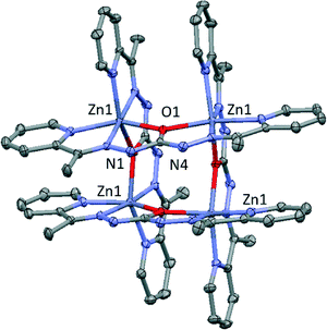 | ||
| Fig. 1 Perspective of the cationic tetranuclear unit in 1. Nitrate anions, solvent molecules and hydrogen atoms have been omitted for clarity. Colour code N = blue, O = red, C = grey, Zn = purple. | ||
In this compound, there are four hydrogen bonds between the tetranuclear square and two nitrate anions generating a trinuclear unit (Fig. S1†). These bonds (2.916 Å) involves N1 from the monoanionic ligand and O3 pertaining to one nitrate molecule. Moreover, there are hydrogen bonds among solvent molecules, specifically O5 (nitrate) and O2 (methanol) with a value of 2.777 Å.
Similar tetranuclear μ-O bridged [2 × 2] square grids were obtained for 2 through the self-assembly of zinc atoms and monoanionic carbohydrazone based ligands. Complex 2 crystallizes in the monoclinic space group P21/n. Crystallographic data and structural refinements for 2 are summarized in Table 1 and S2.† In this case, the structure consists in cationic tetranuclear units of zinc (II) and disordered perchlorate anions (Fig. 2).
 | ||
| Fig. 2 Perspective of the structure 2. Hydrogen atoms have been omitted for clarity. Colour code N = blue, O = red, C = grey, Zn = purple, Cl = green. | ||
In these cationic squares, Zn⋯Zn distances from the sides of the square bridged by oxygen atoms have values of 3.881, 3.910, 3.952 and 3.989 Å, while Zn⋯Zn distance across the diagonals are 5.513 and 5.524 Å. Zn–N distances are in the range of 2.057(3)–2.167(3) Å, whereas Zn–O1 distances have a values between 2.095(3)–2.188(2) Å. Cis and trans angles of metal environment are similar values to those found for 1, highlighting the Zn–O–Zn angles with values in the range 131.97(12)–134.64(12). In the crystal structure it can be observed three hydrogen bonds between one tetranuclear unit and two perchlorate anions generating a trinuclear unit (Fig. S2†). These interactions involves the nitrogen atoms N3 and N15 with two oxygen atoms (O10 and O11) pertaining to Cl2 with values of 2.951 and 2.950 Å, respectively. Moreover, there is other hydrogen bond involving N9 and O18 with a value of 3.000 Å.
Compound 3 crystallizes in the monoclinic space group P21/n and consists of cationic square grids units of zinc (II), two nitrate anions and one tetrahedral [Zn(SCN)4]2− which compensates the charge in the crystalline structure (Fig. 3). Bond distances and angles are summarized in Table S3.†
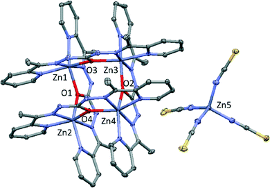 | ||
| Fig. 3 Perspective of the structure 3. Nitrate molecules and hydrogen atoms have been omitted for clarity. Colour code N = blue, O = red, C = grey, Zn = purple, S = yellow. | ||
In these cationic squares, Zn⋯Zn distances from the sides of the square bridged by oxygen atoms have values of 3.889, 3.889, 3.958 and 3.993 Å, while Zn⋯Zn distance across the diagonals are 5.502 and 5.516 Å. Zn–N distances are in the range of 2.059(2)–2.167(3) Å, whereas Zn–O1 distances have a values between 2.095(3)–2.181(2) Å. Cis and trans angles of metal environment are similar values to those found for previous compounds, highlighting the Zn–O–Zn angles with values in the range 132.75(10)–134.80(9). However, unlike the above compounds, there is only one type of hydrogen bond in this structure (Fig. S3†). These H-bonds (2.771 and 2.887 Å) involves the O15 from nitrate anion and N15 and N22 pertaining to two different monoanic ligands from the cationic tetranuclear unit. Moreover, it must be noted that the cationic squares form chains by stacking interaction with values near to 3.521 Å (Fig. S4†).
Compound 4 is a salt in which the asymmetric unit is formed by one anionic [Zn(SCN)4]2− unit, one protonated ligand (H4L2+) and two crystallization methanol molecules (Fig. 4). The compound crystallizes in the triclinic space group P![[1 with combining macron]](https://www.rsc.org/images/entities/char_0031_0304.gif) and bond distances and angles are summarized in Table S4.† It should be mentioned that in this compound, the ligand is protonated in the two nitrogen atoms (N1 and N6) from pyridine rings pertaining to the organic entity. In this structure, there are six different hydrogen bonds (Table 2) involving the two oxygen atoms from the methanol molecules and, on the other hand, the four nitrogen atoms N1, N2, N5 and N6 and the oxygen atom O1, all pertaining to the carbohydrazone based ligand. The hydrogen bonds are in the range 2.708–2.936 Å.
and bond distances and angles are summarized in Table S4.† It should be mentioned that in this compound, the ligand is protonated in the two nitrogen atoms (N1 and N6) from pyridine rings pertaining to the organic entity. In this structure, there are six different hydrogen bonds (Table 2) involving the two oxygen atoms from the methanol molecules and, on the other hand, the four nitrogen atoms N1, N2, N5 and N6 and the oxygen atom O1, all pertaining to the carbohydrazone based ligand. The hydrogen bonds are in the range 2.708–2.936 Å.
 | ||
| Fig. 4 Perspective of the structure 4. Colour code: hydrogen bonds = blue lines, N = blue, O = red, C = grey, Zn = purple, S = yellow. | ||
| Donor | Acceptor | E (2) | Type |
|---|---|---|---|
| BD* and LP, stand for anti-bonding and lone pair orbital, respectively. | |||
| LP (O1) | BD* (C1–N1) | 0.05 | n → π* |
| LP (O1) | BD* (C2–N2) | 0.17 | n → π* |
Compound 5 crystallizes in the tetragonal space group I41/a and consists of cationic tetranuclear units of zinc (II), disordered nitrate anions and one crystallization water molecule. Crystallographic data, structural refinements and bond distances and angles for 5 are summarized in Table 1 and S5,† respectively. Isostructural copper compound was published by Bikas et al.28 In these cationic squares, Zn⋯Zn distance bridged by O1 atom has a value of 3.956 Å, while Zn⋯Zn distance across the diagonal of the square is 5.578 Å. Zn–N distances are in the range of 2.078(3)–2.189(4) Å, whereas Zn–O1 distances have values of 2.137(3) and 2.149 (3) Å. The Zn1–O1–Zn1 angle has a large value of 134.71(11). There is only one type of hydrogen bond in this structure (Fig. 5). This H-bond has a value of 2.853 Å and involves the O5 from nitrate anion and N3 pertaining to the monoanionic ligand from the cationic tetranuclear unit.
 | ||
| Fig. 5 Perspective of the structure 5. Nitrate anions and water molecule have been omitted for clarity. Colour code: hydrogen bonds = blue lines, N = blue, O = red, C = grey, Zn = purple. | ||
3.2. Theoretical study
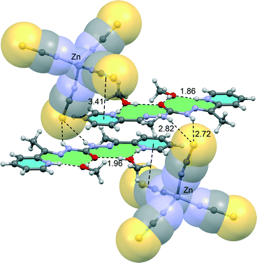
In this part of the manuscript we analyse the interesting and uncommon noncovalent interactions and assemblies observed in the solid state architectures of compounds 3 and 4. In complexes 1, 2 and 5 more conventional and well-studied interactions (H-bonding and π-stacking) are observed in their crystal packing and consequently we have not included them in the theoretical study. Instead we have focused the study to compounds 4 and 3 where anion–π and π–hole interactions,29 respectively, are observed in their crystal structures. The assembly of the diprotonated ligand and the [Zn(NCS)4]2− counterions in 4 is particularly interesting (see Fig. 6). Curiously the protonated pyridine rings do not interact directly with the anion; instead two methanol molecules are situated at these positions acting as a hydrogen bond acceptor and donor and forming a H-bonding network excluding the possibility to form electrostatically enhanced N+–H⋯S bonds. Consequently the [Zn(NCS)4]2− counteions interact with the ligands by means of bifurcated H-bonds with the carbohydrazone moiety and anion–π interactions with the π-system of the protonated pyridine rings.In an effort to rationalize the interactions involving the assembly formed by the ligand and both methanol molecules in 4, we have computed its molecular electrostatic potential surface (MEPS) (see Fig. 7). It can be observed that the most electrostatically positive region (blue colour) is located in the molecular plane (N-bonded hydrogen atoms of carbohydrazone) thus explaining the number of N–H⋯S hydrogen bonds observed in the crystal structure. The electrostatic potential energy values are very large (up to 190 kcal mol−1) due to the dicationic nature of the ligand. Moreover, there is also a strongly positive potential isocontour over the six membered pyrimide rings (see Fig. 7); therefore they are well suited for interacting with electron rich entities.
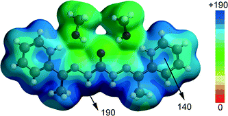 | ||
| Fig. 7 Molecular electrostatic potential surface of the protonated ligand and two methanol molecules. The energy values are given in kcal mol−1. | ||
We have studied energetically the formation of the assembly (see Fig. 8A) using two different equations in order to evaluate the relative importance of the H-bonding and anion–π interactions. Thus, the formation energy has been computed starting from two different binary complexes (ion-pair). In one of both (Fig. 8B) the anion–π has been previously formed and the interaction energy (ΔE1 = −73.9 kcal mol−1) evaluates two bifurcated hydrogen bonds in addition to van der Waals interactions between the ligands. The large interaction energy agrees with the strong electrostatic potential values (see Fig. 8). The interaction energy computed starting from the other binary complex considered in this analysis is ΔE2 = −71.6 kcal mol−1, which is similar to ΔE1 indicating that the strength of the anion–π interaction is similar to the H-bonding and both are fundamental to the stabilization of the assembly.
 | ||
| Fig. 8 (A–C) Theoretical models and binding energies computed to evaluate the noncovalent interactions in compound 4. | ||
In compound 5 we have analysed the π–hole interactions involving the nitrate anions and the imide bond of the carbohydrazone group (see Fig. 9). The best-known π–hole interactions involve carbonyl compounds. For instance, Bürgi and Dunitz30 uncovered the trajectory along which a nucleophile attacks the π–hole of a C-atom of carbonyl. Moreover, π–hole interactions involving amides are known to persist in protein structures.31 However, π–hole interactions involving imine groups are scarcely found in the literature and they are limited to X-ray structures where the N atom is coordinated to metal centers.32 We have firstly studied this issue by examining the MEP surfaces of some simple model systems (picolinaldehyde and 2-pyridinemethanimine) which are shown in Fig. 10. The electrostatic potential over the carbon atom of the carbonyl group is positive (10 kcal mol−1) in picolinaldehyde and slightly negative in 2-pyridinemethanimine (−2 kcal mol−1), thus explaining the ability of the C⋯O to interact with electron rich entities. In order to examine the effect of metal coordination on the potential energy value we have used a sodium atom and a chloride counterion. As a consequence, the electrostatic potential becomes approximately 21 kcal mol−1 more positive over the C atom of the double bond in both compounds.
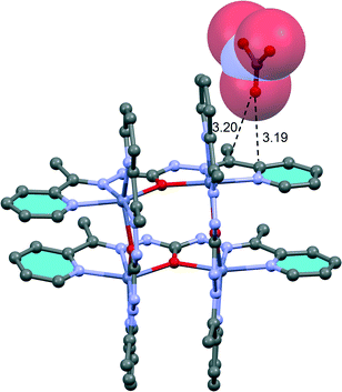 | ||
| Fig. 9 Partial view of the X-ray structure of compound 3. Distances in Å. Hydrogen atoms have been omitted for clarity. | ||
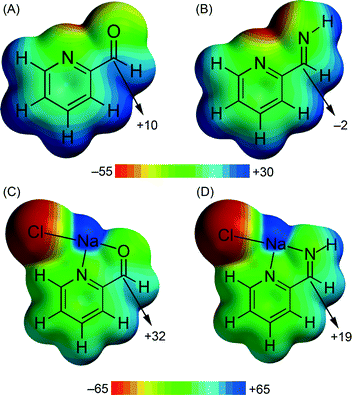 | ||
| Fig. 10 MEP surfaces of picolinaldehyde (A) and 2-pyridine-methanimine (B) model compounds and their complexes (C and D) with NaCl. Energy values in kcal mol−1. | ||
We have evaluated the interaction energy of the π–hole interaction using a theoretical model based on the X-ray structure, since the whole system is computationally unapproachable at the BP86-D3/def2-TZVP level of theory.
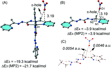
The results are shown in Fig. 11 and the computed binding energy of the π–hole complex is ΔE3 = −19.3 kcal mol−1 confirming the importance of this interaction. In order to analyse the influence of the metal coordination on the binding energy we have computed an additional model where the metal center and the other ligand have been eliminated (see Fig. 11B). As a result the interaction energy is reduced to ΔE4 = −3.9 kcal mol−1 showing the strong influence of the metal coordination on the strength of the interaction in agreement with the MEP analysis (see Fig. 10). For these models we have also computed the interaction energies at the MP2/def2-TZVP level of theory and a good agreement with the BP86-D3 energies have been found giving reliability to the level of theory used in this manuscript. We have used Bader's theory of “atoms-in-molecules”, which provides an unambiguous definition of chemical bonding, to confirm the π–hole interaction described above. In Fig. 11C we show the AIM analysis of the π–hole complex and it can be observed the presence of two bond critical points that connect the oxygen atom of the nitrate with two carbon atoms of the ligand thus confirming the existence of the π–hole interaction. A ring critical point (yellow sphere) is also generated as a consequence of the formation of the supramolecular ring. The value of the Laplacian of the charge density computed at the bond critical points is positive, as is common in closed-shell interactions. The charge density values at the bond CPs are comparable to other π–hole interactions.33 Finally, we have also studied the importance of orbital effects in the π–hole interaction by performing natural bond orbital (NBO) calculations. We have focused our attention on the second order perturbation analysis, since it is a convenient tool to study donor–acceptor interactions.34 In π–hole complex shown in Fig. 11B we have found two modest contributions originated from the donation of one lone pair orbital (LP) of the oxygen atom to the antibonding C–N orbitals (π*) of the ligand (see Table 2). This observation confirms the π–hole nature of the noncovalent interactions in this complex. It is also worth mentioning that the magnitude of the orbital interaction is higher in the imino bond than in the aromatic ring.
3.3. Hirshfeld surface analysis
On the Hirshfeld surface of complex ion in 1 mapped with dnorm function one can notice four large red areas (Fig. 12), which correspond to one strong hydrogen bond (N1–H1⋯O3) formed between hydrazone nitrogen atom and oxygen atom of one of the nitrate anions. Additionally several smaller red spots can be noticed. Twelve of them are due to presence of weak C–H⋯O interactions. The remaining eight are in accordance with close contacts between hydrogen atoms of methyl groups of ligand molecules.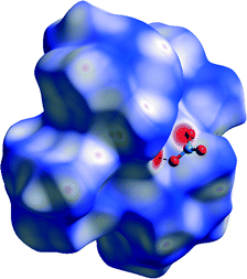 | ||
| Fig. 12 Hirshfeld surface of 1 mapped with dnorm function. Dashed lines indicate N–H⋯O hydrogen bonds. Small red spots on the surface indicate C–H⋯O and H⋯H interactions. | ||
This indicates that van der Waals interactions play a very important role in formation of crystals as proven by analysis of decomposed fingerprint plots (50.8%, Fig. S5a†). On the Hirshfeld surface mapped with shape index function one can notice both red regions corresponding to C–H ⋯ π interactions as well as ‘bow-tie patterns’ which indicate presence of aromatic stacking interactions (Fig. 13). Analysis of decomposed fingerprint plots provide information about major forces contributing to the cohesion of ions in the structure of 1. These are van der Waals forces (50.8%) and hydrogen bonds in which oxygen atom acts as the donor (27.2%). Asymmetry of the fingerprint plot can be explained by the fact that in all H⋯O interactions the complex ion donates the hydrogen atom which is situated inside the H surface.
Analysis of the Hirshfeld surface of the complex ion in the structure of 3 mapped with dnorm function reveals several red areas indicating close contacts between atoms on both sides of the surface (Fig. 14). Two biggest of them correspond to two hydrogen bonds formed between protonated hydrazone nitrogen atoms of two different ligand moieties and one oxygen atom of one of the nitrate ions (N15–H15N⋯O15, N22–H22N⋯O15). One additional red area is in accordance with N–H⋯S hydrogen bond between complex ion and [Zn(SCN)4]−2 ion (N4–H4N⋯S3S).
 | ||
| Fig. 14 Hirshfeld surface of 3 mapped with dnorm function. Interactions with nitrate ions shown on the left, while interactions with [Zn(SCN)4]−2 ion shown on the right. | ||
Three medium sized red areas are due to three stronger C–H⋯O interactions connecting the complex ion and the nitrate ion mentioned above. Moreover there are several smaller red spots corresponding to weaker C–H⋯O, C–H⋯S and C–H⋯C interactions which bind complex ion with [Zn(SCN)4]2− and nitrate anions. Mapping of the H surface with shape index function reveals similar colour patterns than in 1 which indicates presence of both π⋯π and C–H⋯π interactions (Fig. 15). When decomposed fingerprint plots are analysed it is revealed that van der Waals forces (H⋯H contacts) play the most important role in packing of the species in the structure (35.3%).
Since percentage of the surface taken by H⋯C, H⋯O and H⋯S interactions are very similar (17.4%, 15.6% and 12.7%, respectively) one can assume that C–H⋯π stacking interactions and strong N–H⋯O and N–H⋯S hydrogen bonds contribute almost equally to packing in structure of 1 (Fig. S6†). Asymmetry of the fingerprint plot is caused – similarly to 1 – by the fact that oxygen and sulphur atoms which are acceptors of H bonds are situated outside of the surface.
For the analysis of packing interactions in 4 Hirshfeld surface of the ligand ion has been calculated. When it was mapped with dnorm function the most prominent feature are four large red spots which correspond to four strong hydrogen bonds linking two lattice methanol molecules and ligand molecule (N1–H1⋯O1, N6–H9⋯O2, O2–H3O⋯O1 and O2–H2O⋯O1; Fig. 16, left). Next two smaller red spots indicate presence of hydrogen bonds connecting ligand molecule and [Zn(SCN)4]2− ion (N3–H3⋯S3, N4–H4⋯S3). Moreover there are three small areas which are in agreement with existence of weak C–H⋯S and C–H⋯N interactions. Shape index function applied to the surface allows to pinpoint ion⋯π interactions which were predicted in DFT calculations (indicated with arrow on Fig. 16, right). Decomposed fingerprint plots indicate that van der Waals forces (H⋯H interactions, 24.5%), and various hydrogen bonds (H⋯N, H⋯S and H⋯O contacts; 18.2%, 17.9% and 9.4% respectively) contribute mostly to packing of the species in the crystal (Fig. S7†). Similar to other presented compounds, distinctive asymmetry can be noticed.
 | ||
| Fig. 16 Left, Hirshfeld surface of ligand in the structure of 4 mapped with dnorm function. Right, Hirshfeld surface of ligand ion in 4 mapped with shape index function. | ||
Hirshfeld surface of the complex ion in 5 mapped with dnorm function is dotted with several small red spots. Eight of them indicate presence of short H⋯H contacts between hydrogen atoms of methyl groups. This suggests that van der Waals forces play an important role in the packing as is confirmed by decomposed fingerprint plots (Fig. S8†). Additional eight red areas are consistent with H⋯C close contacts which correspond to C–H⋯π interactions (also recognizable on H surface mapped with shape index function, Fig. 18). The rest of the red spots correspond to several weak C–H⋯O interactions in which pyridyl ring and methyl group carbon atoms act as donors and oxygen atoms of nitrate ions are the acceptors (Fig. 17). With shape index applied Hirshfeld surface of the complex ion is similar to that in 1 and 3. Abovementioned C–H⋯π interactions can be noticed as big red areas and stacking interactions are visible as ‘bow-tie’ patterns (both marked with arrows on Fig. 18). When considering decomposed fingerprints plots (Fig. S4†) one can draw the conclusion that two most prominent type of interactions in packing of the crystals of 5 are van der Waals forces (34.0%) and weak C–H⋯O hydrogen bonds (36.4%).
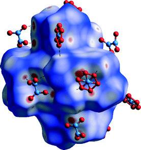 | ||
| Fig. 17 Hirshfeld surface of 5 mapped with dnorm function. C–H⋯O hydrogen bonds marked with dashed lines. | ||
Comparison of Hirshfeld surfaces and decomposed fingerprint plots of compounds 1, 3 and 5 leads to a few conclusions: 1) in all cases van der Waals forces and stacking interactions play the most important role in stacking of coordination cations; 2) second type of interactions are hydrogen bonds (both weak and strong) in which donor atoms are oxygen atoms of nitrate counterions or sulphur atoms of [Zn(SCN)4]2− ions; 3) asymmetry of the fingerprint plots of all three compounds is caused by the fact that acceptor atoms mentioned in point 2 are located outside of the Hirshfeld surface.
Conclusion
We have synthesized and X-ray characterized five Zn(II) complexes formed by cationic tetranuclear units of zinc (II), with different anions and crystallization solvent molecules. The solid state structures show that the participation of the organic ligand and anionic co-ligands in concurrent hydrogen bonding, π–hole, and anion–π interactions control the crystal packing. Some of them have been analysed using DFT calculations and MEP surfaces. In compound 4, the anions have the ability to link the cationic ligands together via anion–π interactions and H-bonding interactions providing remarkable supramolecular anion–π/H-bond type network for self-assembly progression. In compound 3, we have analysed π–hole interactions in the solid state involving the coordinated imine groups of the ligand. Interestingly, this compound represents a novel example of supramolecular system bearing π–hole interactions. The computational study highlights the impact of unconventional interactions on the final structure and the calculation of the energetic features of the different noncovalent interactions contributes to understand the mechanism that governs the molecular recognition and crystal packing.Acknowledgements
We are grateful to the University of Maragheh for the generous financial support of this research. A. B. and A. F. thank DGICYT of Spain (projects CTQ2014-57393-C2-1-P and CONSOLIDER INGENIO CSD2010-00065, FEDER funds) for funding. We thank the CTI (UIB) for free allocation of computer time.Notes and references
- (a) M. D. Allendorf, A. Schwartzberg, V. Stavila and A. A. Talin, Chem. – Eur. J., 2011, 17, 11372 CrossRef CAS PubMed; (b) A. R. Stefankiewicz and J.-M. Lehn, Chem. – Eur. J., 2009, 15, 2500 CrossRef CAS PubMed; (c) E. M. Zueva, E. R. Ryabikh and S. A. Borshch, Inorg. Chem., 2011, 50, 11143 CrossRef CAS PubMed.
- (a) L. N. Dawe, T. S. M. Abedin and L. K. Thompson, Dalton Trans., 2008, 1661–1675 RSC; (b) L. N. Dawe, K. V. Shuvaev and L. K. Thompson, Chem. Soc. Rev., 2009, 38, 2334–2359 RSC; (c) A. M. Stadler, Eur. J. Inorg. Chem., 2009, 4751–4770 CrossRef CAS; (d) M. Ruben, J. Rojo, F. J. Romero-Salguero, L. H. Uppadine and J. M. Lehn, Angew. Chem., Int. Ed., 2004, 43, 3644–3662 CrossRef CAS PubMed; (e) M. Ruben, J. M. Lehn and P. Muller, Chem. Soc. Rev., 2006, 35, 1056–1067 RSC; (f) O. Waldmann, J. Hassmann, P. Muller, G. S. Hanan, D. Volkmer, U. S. Schubert and J. M. Lehn, Phys. Rev. Lett., 1997, 78, 3390–3393 CrossRef CAS; (g) A. M. Stadler and J. Harrowfield, Inorg. Chim. Acta, 2009, 362, 4298–4314 CrossRef CAS.
- A. M. Stadler, C. Burg, J. Ramirez and J. M. Lehn, Chem. Commun., 2013, 49, 5733–5735 RSC.
- (a) Y. Yu, D. S. Kalinowski, Z. Kovacevic, A. R. Siafakas, P. J. Jansson, C. Stefani, D. B. Lovejoy, P. C. Sharpe, P. V. Bernhardt and D. R. Richardson, J. Med. Chem., 2009, 52, 5271–5294 CrossRef CAS PubMed; (b) L. K. Thompson, Coord. Chem. Rev., 2002, 233, 193–206 CrossRef.
- (a) V. A. Milway, V. Niel, T. S. M. Abedin, Z. Q. Xu, L. K. Thompson, H. Grove, D. O. Miller and S. R. Parsons, Inorg. Chem., 2004, 43, 1874–1884 CrossRef CAS PubMed; (b) Z. Xu, L. K. Thompson, C. J. Matthews, D. O. Miller, A. E. Goetaand and J. A. K. Howard, Inorg. Chem., 2001, 40, 2446–2449 CrossRef CAS PubMed; (c) K. Shuvaev, L. N. Dawe and L. K. Thompson, Dalton Trans., 2010, 39, 4768 RSC.
- (a) M. U. Anwar, L. K. Thompson, L. N. Dawe, F. Habib and M. Murugesu, Chem. Commun., 2012, 48, 4576–4578 RSC; (b) N. M. Randell, M. U. Anwar, M. W. Drover, L. N. Dawe and L. K. Thompson, Inorg. Chem., 2012, 52, 6731–6742 CrossRef PubMed; (c) M. Moustapha-Sow, O. Diouf, M. Gaye, A. Salam-Sall, G. Castro, P. Perez-Lourido, L. Valencia, A. Caneschi and L. Sorace, Cryst. Growth Des., 2013, 13, 4172–4176 CrossRef CAS.
- (a) M. S. Gargari, G. Mahmoudi, S. R. Batten, V. Stilinović, D. Butler, L. Beauvais, W. S. Kassel, W. G. Dougherty and D. VanDerveer, Cryst. Growth Des., 2015, 15, 1336–1343 CrossRef; (b) G. Mahmoudi, A. A. Khandar, J. K. Zareba, M. J. Białek, M. S. Gargari, M. Abedi, G. Barandika, D. van Derveer, J. Mague and A. Masoumi, Inorg. Chim. Acta, 2015, 429, 1–14 CrossRef CAS.
- E. P. Manoj, M. R. P. P. Kurup and H.-K. Fun, Inorg. Chem. Commun., 2007, 10, 324–328 CrossRef CAS.
- S.-Y. Qi, Z.-M. Li, T.-L. Zhang, Z.-N. Zhou, L. Yang, J.-G. Zhang, X.-J. Qiao and K.-B. Yu, Acta Chim. Sin., 2011, 69, 987–992 CAS.
- J. S. Murray, P. Lane, T. Clark, K. E. Riley and P. Politzer, J. Mol. Model., 2012, 18, 541–548 CrossRef CAS PubMed.
- (a) A. Frontera, P. Gamez, M. Mascal, T. J. Mooibroek and J. Reedijk, Angew. Chem., Int. Ed., 2011, 50, 9564 CrossRef CAS PubMed; (b) A. Bauzá, D. Quiñonero, P. M. Deyà and A. Frontera, 2636–2641, New J. Chem., 2013, 37 Search PubMed; (c) A. Bauzá, D. Quiñonero, P. M. Deyà and A. Frontera, Chem. Phys. Lett., 2013, 37, 2636–2641 Search PubMed.
- G. M. Sheldrick, SADABS, Program for Empirical Adsorption Correction, Institute for Inorganic Chemistry, University of Gottingen, Germany, 1996 Search PubMed.
- G. M. Sheldrick, SHELX-97, Program for Crystal Structure Refinement, University of Göttingen, Göttingen, Germany, 1997 Search PubMed.
- R. Ahlrichs, M. Bär, M. Häser, H. Horn and C. Kölmel, Chem. Phys. Lett., 1989, 162, 165 CrossRef CAS.
- (a) A. Bauzá, A. Terrón, M. Barceló-Oliver, A. García-Raso and A. Frontera, Inorg. Chim. Acta, 2015 DOI:10.1016/j.ica.2015.04.028; (b) D. Sadhukhan, M. Maiti, G. Pilet, A. Bauzá, A. Frontera and S. Mitra, Eur. J. Inorg. Chem., 2015, 11, 1958–1972 CrossRef; (c) M. Mirzaei, H. Eshtiagh-Hosseini, Z. Bolouri, Z. Rahmati, A. Esmaeilzadeh, A. Hassanpoor, A. Bauzá, P. Ballester, M. Barceló-Oliver, J. T. Mague, B. Notash and A. Frontera, Cryst. Growth Des., 2015, 15, 1351–1361 CrossRef CAS; (d) P. Chakraborty, S. Purkait, S. Mondal, A. Bauzá, A. Frontera, C. Massera and D. Das, CrystEngComm, 2015, 17, 4680–4690 RSC.
- S. F. Boys and F. Bernardi, Mol. Phys., 1970, 19, 553–566 CrossRef CAS.
- Spartan 10′, v. 1.10, Wavefunction Inc, Irvin, CA, USA Search PubMed.
- R. F. W. Bader, Chem. Rev., 1991, 91, 893–928 CrossRef CAS.
- T. A. Keith, AIMAll (Version 13.05.06), TK Gristmill Software, Overland Park KS, USA, 2013 Search PubMed.
- (a) J. J. McKinnon, D. Jayatilaka and M. A. Spackman, Chem. Commun., 2007, 3814 RSC; (b) M. A. Spackman, J. J. McKinnon and D. Jayatilaka, CrystEngComm, 2008, 10, 377 CAS; (c) M. A. Spackman and D. Jayatilaka, CrystEngComm, 2009, 11, 19 RSC; (d) H. F. Clausen, M. S. Chevallier, M. A. Spackman and B. B. Iversen, New J. Chem., 2010, 34, 193 RSC; (e) S. K. Seth, D. Sarkar, A. Roy and T. Kar, CrystEngComm, 2011, 13, 4528 RSC; (f) S. K. Seth, V. S. Lee, J. Yana, S. M. Zain, A. C. Cunha, V. F. Ferreira, A. K. Jordao, M. C. B. V. De Souza, S. M. S. V. Wardell, J. L. Wardell and E. R. T. Tiekink, CrystEngComm, 2015, 17, 2255 RSC; (g) S. K. Seth, I. Saha, C. Estarellas, A. Frontera, T. Kar and S. Mukhopadhyay, Cryst. Growth Des., 2011, 11, 3250 CrossRef CAS; (h) S. K. Seth, D. Sarkar, A. D. Jana and T. Kar, Cryst. Growth Des., 2011, 11, 4837 CrossRef CAS; (i) S. K. Seth, D. Sarkar, A. Roy and T. Kar, CrystEngComm, 2011, 13, 6728 RSC; (j) P. Manna, S. K. Seth, A. Das, J. Hemming, R. Prendergast, M. Helliwell, S. R. Choudhury, A. Frontera and S. Mukhopadhyay, Inorg. Chem., 2012, 51, 3557 CrossRef CAS PubMed; (k) M. Mitra, S. K. Seth, S. R. Choudhury, P. Manna, A. Das, M. Helliwell, A. Bauzá, A. Frontera and S. Mukhopadhyay, Eur. J. Inorg. Chem., 2013, 4679 CrossRef CAS; (l) S. K. Seth, CrystEngComm, 2013, 15, 1772 RSC; (m) M. J. Białek, J. K. Zaręba, J. Janczak and J. Zoń, Cryst. Growth Des., 2013, 13, 4039–4050 CrossRef; (n) J. K. Zaręba, M. J. Białek, J. Janczak, J. Zoń and A. Dobosz, Cryst. Growth Des., 2014, 14, 6143–6153 CrossRef.
- (a) M. A. Spackman and P. G. Byrom, Chem. Phys. Lett., 1997, 267, 215 CrossRef CAS; (b) J. J. McKinnon, A. S. Mitchell and M. A. Spackman, Chem. – Eur. J., 1998, 4, 2136 CrossRef CAS.
- J. J. McKinnon, M. A. Spackman and A. S. Mitchell, Acta Crystallogr., Sect. B: Struct. Sci., 2004, 60, 627 CrossRef PubMed.
- (a) A. L. Rohl, M. Moret, W. Kaminsky, K. Claborn, J. J. Mckinnon and B. Kahr, Cryst. Growth Des., 2008, 8, 4517 CrossRef CAS; (b) P. Manna, S. K. Seth, M. Mitra, A. Das, N. J. Singh, S. R. Choudhury, T. Kar and S. Mukhopadhyay, CrystEngComm, 2013, 15, 7879 RSC; (c) S. K. Seth, Inorg. Chem. Commun., 2014, 43, 60 CrossRef CAS; (d) S. K. Seth, J. Mol. Struct., 2014, 1064, 70 CrossRef CAS; (e) S. K. Seth, J. Mol. Struct., 2014, 1070, 65 CrossRef CAS.
- M. A. Spackman and J. J. McKinnon, CrystEngComm, 2002, 4, 378 RSC.
- S. K. Wolff, D. J. Grimwood, J. J. McKinnon, D. Jayatilaka and M. A. Spackman, CrystalExplorer 2.1, University of Western Australia, Perth, Australia, 2007 Search PubMed.
- F. H. Allen, O. Kennard, D. G. Watson, L. Brammer, A. G. Orpen and R. Taylor, J. Chem. Soc., Perkin Trans. 2, 1987, S1 RSC.
- J. J. Koenderink and A. J. van Doorn, Image Vis. Comput., 1992, 10, 557 CrossRef.
- R. Bikas, H. Hosseini-Monfared, P. Aleshkevych, R. Szymczak, M. Siczek and T. Lis, Polyhedron, 2015, 88, 48–56 CrossRef CAS.
- (a) A. Bauzá, T. J. Mooibroek and A. Frontera, ChemPhysChem, 2015, 16, 2496 CrossRef PubMed; (b) A. Bauzá and A. Frontera, Angew. Chem., Int. Ed., 2015, 54, 7340 CrossRef PubMed.
- (a) H. B. Bürgi, Inorg. Chem., 1973, 12, 2321–2325 CrossRef; (b) H. B. Bürgi, J. D. Dunitz and E. Shefter, J. Am. Chem. Soc., 1973, 95, 5065–5067 CrossRef; (c) H. B. Bürgi, J. D. Dunitz, J. M. Lehn and G. Wipff, Tetrahedron, 1974, 30, 1563–1572 CrossRef.
- (a) P. H. Maccallum, R. Poet and E. J. Milnerwhite, J. Mol. Biol., 1995, 248, 374–384 CAS; (b) G. J. Bartlett, A. Choudhary, R. T. Raines and D. N. Woolfson, Nat. Chem. Biol., 2010, 6, 615–620 CrossRef CAS PubMed; (c) M. Harder, B. Kuhn and F. Diederich, ChemMedChem, 2013, 8, 397–404 CrossRef CAS PubMed.
- A. Bhattacharyya, P. K. Bhaumik, A. Bauzá, P. P. Jana, A. Frontera, M. G. B. Drew and S. Chattopadhyay, RSC Adv., 2014, 4, 58643–58651 RSC.
- (a) A. Bauzá and A. Frontera, ChemPhysChem, 2015, 16, 3108–3113 CrossRef PubMed; (b) A. Bauzá and A. Frontera, ChemPhysChem, 2015 DOI:10.1002/cphc.201500757; (c) A. Bauzá and A. Frontera, Phys. Chem. Chem. Phys., 2015, 17, 24748–24753 RSC; (d) A. Bauzá and A. Frontera, Chem. Phys. Lett., 2015, 633, 282–286 CrossRef.
- F. Weinhold and C. R. Landis, Valency and Bonding: A Natural Bond Orbital Donor-Acceptor Perspective, Cambridge University Press, Cambridge,UK, 2005 Search PubMed.
Footnote |
| † Electronic supplementary information (ESI) available. CCDC 1426269–1426273 contain the supplementary crystallographic data for this paper. For ESI and crystallographic data in CIF or other electronic format see DOI: 10.1039/c5ce01915j |
| This journal is © The Royal Society of Chemistry 2016 |


