 Open Access Article
Creative Commons Attribution 3.0 Unported Licence
Direct observation of structural changes near and at the charge-ordering temperature of ilvaite using high-flux neutron powder diffraction†
E. R.
Williams
b and
M. T.
Weller
*a
aDepartment of Chemistry, University of Bath, Claverton Down, Bath, BA2 7AY, UK. E-mail: m.t.weller@bath.ac.uk
bDepartment of Chemistry, University of Southampton, Southampton, UK
First published on 8th April 2014
Abstract
The detailed structural changes that occur during and following the formation of a long-range, charge-ordered state have been accurately and rapidly determined. The localisation of the electron in ilvaite, Ca(Fe,Mn)3Si2O8(OH), forming Fe2+ and Fe3+ from the delocalized 2× Fe2.5+, is directly apparent in bond valence sums derived from accurately determined Fe–O distances extracted from neutron powder diffraction data obtained for 40 temperatures around the charge ordering temperature in just a few hours. Subtle changes that occur in the structure and lattice parameters after the formation of the charge-ordered state are also apparent for the first time from this work.
Charge-ordering behaviours occurring in materials represent an area of intense current research interest including studies of systems such as the manganites, LaMnO3, Pr0.5Sr0.5MnO3 and La1.2Sr1.8Mn2O7;1 CaFeO3,2 TbBaFe2O5,3 Fe2OBO3,4 LuFe2O4,5 Ca2−xNaxCuO2Cl2,6 Fe3O4,7 La1.67Sr0.33NiO4,8 and YBaCo2O5.9 In such systems the direct investigation of the charge-ordering transition is best achieved through the application of structure determination techniques, such as X-ray diffraction, neutron diffraction and EXAFS, which all show the gross changes in structure that occur as the charge localizes. Of these techniques neutron diffraction provides the most accurate information as the charge-ordering phenomenon is normally associated with small changes in metal to oxygen bond lengths as a result of electron localization; analysis of neutron diffraction data produces accurate and precise definition of the oxygen nuclear positions in the presence of heavier metals, derived from the large scattering length of oxygen. While single crystal neutron diffraction data provide the most accurate structure models, the requirement for large crystals and very long experimental times, where a significant temperature range has to be studied, often prohibits such experiments. Profile fitting of neutron powder diffraction (NPD) data also produces accurate metal–oxygen distances but low neutron fluxes require extended experimental count times, typically a few hours per full diffraction profile; this has again limited the range and resolution of variable temperature work covering a full charge-ordering event so, for example, published NPD work on YBaCo2O5,9 and Fe2OBO3,4 were both limited to just a few temperatures though the recent study of short-range charge ordering in La1.67Sr0.33NiO4,8 completed over 3 days on a 15 g sample is noteworthy. Careful and detailed studies of charge-ordering in materials, such as with TbBaFe2O5,3 can show additional anomalies in physical properties and unit cell volumes associated with premonitory or post-monitory transitions derived from local order or relaxation – however, structural changes associated with such transitions have not been resolved before. In this communication we report a detailed study of the charge ordering behaviour in CaFe2(Fe,Mn)Si2O8(OH), which occurs as the natural mineral ilvaite, using a very high flux NPD instrument on a 1.5 g sample in a 6 h experiment. The use of a high flux NPD instrument allows an unprecedented accurate resolution of the charge-ordering process enabling direct observation of the electron localization through determination of site changes and, for the first time, investigation of the subtle changes that occur in the structure just below the charge-ordering temperature.
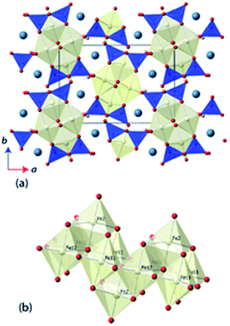
Ilvaite, CaFe2FeSi2O8(OH), is a mixed valence Fe-bearing naturally-occurring sorosilicate, in which long range charge-ordering has been observed to be associated with a phase transition between orthorhombic and monoclinic crystal systems.10,11 A schematic representation of the monoclinic structure of ilvaite is shown in Fig. 1. Edge-sharing double octahedra, FeO5(OH), chains align parallel to the c-axis, with further Fe-centred octahedra sitting above and below the chain sharing four edges. Hydroxy-groups line the edges of the chains, hydrogen bonding to the apical sites of octahedra in neighboring chains. The Fe-containing chains are linked by disilicate, Si2O7, units to form a three-dimensional structure containing seven-coordinated Ca2+ cations. In the charge-disordered orthorhombic form two distinct octahedral iron sites M1 and M2, exist where M1 is a mixed valence Fe2+/3+ site, whilst M2 is entirely Fe2+ ordered; in natural ilvaites substitution of Mn2+ cations may occur into the M2 site.12,13 In the charge-ordered monoclinic form the M1 octahedral sites resolves as two independent crystallographic sites, M11 (Fe2+) and M12 (Fe3+).14,15 The degree of Fe2+/Fe3+ ordering within ilvaite also dictates the extent of deviation from orthorhombic symmetry, with β-angles up to 90.45° reported for complete ordering and β = 90.00° for entirely disordered Fe2+/Fe3+ sites.16,17 Ghose et al. investigated ilvaite below room temperature (305–5 K) using neutron powder diffraction (NPD) and showed charge-ordering between the M11 and M12 sites existed over this temperature range.18 A subsequent, higher temperature study using single crystal X-ray diffraction (295–400 K) extracted structural parameters at five 20 K intervals and above the transition temperature (TCO) of ∼346 K, changes in the Fe–O bond lengths within the Fe-octahedra, indicate complete charge disorder with the iron valence on both sites having converged towards 2.5+. Previous studies into the charge-ordering effects on structure in ilvaite and other materials, such as YBaCo2O5, as a function of temperature have required a long data collection time at each temperature; this is particularly so for NPD data. This generally results in a coarse data set with structural information extracted at only a few temperatures around TCO or reduced bond length accuracy from the use of X-ray diffraction methods. The lack of temperature resolution with data collected at only a few temperatures, either with single crystal X-ray diffraction or NPD, can be limiting in the investigation of the behavior of structures near TCO. We have used the high-flux neutron powder diffractometer, D20 at the ILL, to extract rapidly, and with accurate structural resolution, a full model of the long range charge-ordering and so determine the resulting structural changes in ilvaite below and through its monoclinic to orthorhombic transition temperature.
A sample of ilvaite (1.5 g, phase pure) from Dalnegorsk, Russia, was ground to a fine homogenous powder was studied on the D20 high flux neutron powder diffractometer at the ILL, Grenoble (λ = 1.87 Å).19 Following mounting in a cylindrical vanadium can, the sample was cooled to 140 K in a cryostat, allowing for a stabilisation time of 10 minutes, before ramping at 0.7 K min−1 to 380 K with a total data collection time of under 6 hours. With this relatively slow heating rate, little or no thermal gradient exists across the 1.5 g sample. Data were binned as 10 minute sets before further analysis; the temperature associated with each of these binned data sets was taken as that at mid-point of the data collection corrected for thermal lag between the measurement thermocouple and the sample.20 To confirm the accuracy of this method very high quality NPD patterns were also collected on the D2B high resolution diffractometer (λ = 1.594 Å) at the Institut Laue Langevin, Grenoble, France.21 Diffraction patterns were collected over 180 minutes at four temperatures, 100, 298, 575 and 800 K, with samples mounted in cylindrical vanadium cans before being placed in a DISPLEX cryofurnace (100 K), suspended in the beam (298 K) or placed in a furnace (575, 800 K) before cooling/heating to the desired temperature. A thermal equilibration time of 15 minutes was allowed between each temperature change and data collection commencement. The unit cell parameters and atomic coordinates of ilvaite were extracted from each dataset through Rietveld profile refinement,22 using the GSAS suite of programs and the EXPGUI graphical user interface.23,24 The initial structural refinement against the data obtained at 100 K on D2B started with the monoclinic structure model described by Finger and Hazen.15 All atomic positions and ADPs were refined, and the M2 position was found to contain 30(1)% Mn. The final model obtained with the 100 K data was used as an initial model for the structural refinement of all other D2B data sets using the final model from the previous temperature block as a starting point for the next. The 575 and 800 K D2B data sets were refined against an orthorhombic initial model,25 as the sample temperature was greater than TCO. Similarly, the monoclinic 100 K – D2B model was used as an initial model for the first data set collected on D20, before carrying out a sequential GSAS refinement against all D20 data sets and extracting the required structural information.
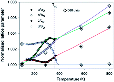
Fig. 2 shows the evolution of the lattice parameters in ilvaite between 100 and 800 K focusing on the D20 data from 100 K to just above TCO. Note that there is a very small systematic error between lattice parameter data extracted from D20 and D2B, likely to be due to instrumental differences, but overall values are in excellent agreement and trends in data readily resolved. The 7 K temperature resolution in the D20 data, derived from the data binning, coupled with the inherent precision in lattice parameters obtained from NPD (due to the strong scattering at high diffraction angles) allows the cell parameter behaviour as a function of temperature on approaching and exceeding a charge-ordering process to be deciphered much more clearly than previously.25 As reported in this earlier work one of the most significant changes is in β, which decreases from a refined value in the monoclinic structure description of 90.252(5) (at its maximum at 250 K) to 90.05(2)° as the cell becomes orthorhombic at TCO. TCO is estimated to be 352 K in this sample with 30% Mn on the M2 site close to the value reported by Ghose of 346 K for a sample with less than 1% Mn. However, between 150 K and 280 K β is observed to increase marginally as the structure expands rapidly in the c lattice direction but, notably, it contacts along a. Between 280 K and TCO = 352 K as β decreases rapidly, the a-axis expands and the expansion along the c direction halts; the b lattice parameter expands normally over the full temperature range studied. Some faint evidence of these more subtle changes in lattice parameters can be seen in the work of Ghose;14,25 for example, an increase in a may be discerned near TCO but the data were of insufficient precision and number to be confident of such trends. The anomalous behaviours of a, c and β near TCO can be associated with the onset of charge ordering and these, plus the contraction along a and the very rapid expansion along c between 150 and 280 K, require further analysis of the bond lengths and derived charge distribution, vide infra. M–O distances were extracted from the crystallographic model refined against NPD data at each temperature. It is also worth noting that with NPD data the hydrogen position and the strength of the moderately strong O–H⋯O hydrogen bond (O⋯O ∼ 2.6 Å) can also be monitored; however, the O–H bond length was found to behave normally over the full temperature range studied showing a small monotonic increase in length, i.e. no change in this part of the structure occurred on charge ordering. The derived M–O distances can be used to calculate bond valence sums (BVSs) for individual metal sites according to the method of Brown and Altermatt26 and, therefore, assign charges each site. For these calculations r0 values for both Fe3+ and Fe2+ were initially explored for each unique iron site and the BVSs obtained used to identify the associated valence state. Thus the use of the Fe2+r0 value for a site occupied by Fe3+ leads to BVS values around 2.3 to 2.4 + instead of the expected 2.0 ± 0.15 (if occupied by by Fe2+), indicating that the Fe3+r0 value is applicable for this site. Similarly the use of the r0 value for Fe3+ for a site in reality occupied by Fe2+ also yields values near 2.4+ rather than the expected 2.0 ± 0.15 expected with the correct choice of r0 for Fe2+. Note that the use of the incorrect r0 value is clearly shown in these calculations but the BVSs obtained with the correct r0, while lying close to the expected BVS (2+ or 3+), do not fully reach the value of the higher or lower oxidation state BVS. This indicates some residual structural strain in the material after charge-ordering occurs in that the oxide ion geometry cannot fully relax, so an Fe2+ site remains compressed and the Fe3+ site coordination over-expanded. Furthermore BVSs are expected to decrease slightly with increasing temperature due to thermal expansion.
 | ||
| Fig. 2 Variation of the normalized, against the minimum value obtained, lattice parameters as a function of temperature.† Lines are best fit to the D20 data and have been extended as a guide to the eye into the regions covered by the D2B data. | ||
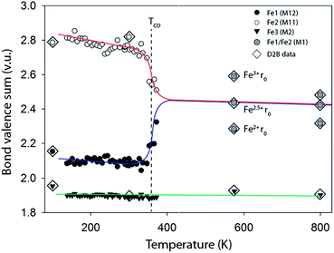
For the monoclinic form at 100 K the BVS analysis clearly assigned M2 (70% Fe, 30% Mn) as purely M2+ and M11 as Fe2+ and M12 as Fe3+ in agreement with the previous reports.25 Calculations of BVSs were then undertaken with appropriate r0 values for all 40 temperatures and Fig. 3 presents these data for the three independent metal sites of the monoclinic phase. For the orthorhombic phase above TCO M11 and M12 become equivalent and BVS were carried out for the single site using Fe2+ and Fe3+r0 values and also using an r0 value estimated for Fe2.5+; all three BVS calculated values are plotted in Fig. 3. The charge ordering in ilvaite is clearly seen in this plot and occurs gradually between 300 and 380 K and is essentially complete at TCO = 362 K in agreement with the lattice parameter data. Below TCO M11 is occupied by Fe3+ while the electron charge localises on M12 producing Fe2+. In both monoclinic and orthorhombic forms the BVSs decrease slightly with the increasing temperature as expected due to thermal expansion and increases in Fe–O distances.
 | ||
| Fig. 3 Bond valence sums for the three transition metal sites in ilvaite calculated using the Fe3+r0 values for M11 and Fe2+r0 parameter for M12 and M2.† For the two high temperature data points in the orthorhombic phase where M11 is equivalent to M12, M1, with an average oxidation state of 2.5+ the BVS was calculated with Fe2+, Fe2.5+ and Fe3+r0 values. | ||
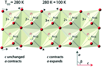
The anomalous behaviours in the lattice parameters noted earlier can now also be interpreted. Considering the behaviour as a sample of ilvaite is cooled from 360 and 280 K and the charge-ordering occurs and the a and b axes contact normally while c is almost invariant; this behaviour is associated with the rapid relocation of the edge-shared oxygen atoms along c and closer to M11 with its higher formal charge Fe3+ and away from M12, Fig. 4. This relocation is, as would be expected with equal numbers of bond lengthening and shortening, almost distance neutral along c, while a and b contract with decreasing thermal motion. The BVS for the M11 site increases most rapidly on cooling between 280 K and 100 K indicating that over this temperature range the loss of thermal energy after charge-ordering has occurred causes the oxide anions to continue to move towards this site while the BVSs for M12 indicate that distances around this site change little on further cooling involving a combination of a slight decrease along c but increase along a. This further significant displacement towards M11 but almost unchanged M12–O distances causes a “concertina” effect and is responsible for the observed changes in lattice parameters seen Fig. 1. The c-lattice parameter contracts rapidly as a result of continued reduction in M11–O distances along this direction while a expands as the oxygen maintains its O–M12 distance. Fig. 4 shows a portion of the double chain of edge sharing octahedra centred on M11 and M12 in the ilvaite structure and the major displacements in oxide ion positions that occur at just below TCO and then further cooling from 280 K to 150 K. These displacements lie mainly in the ac plane while the b direction remains almost unaffected and contracts normally on cooling.
 | ||
| Fig. 4 Ordered Fe11 and Fe12 layer in the charge ordered state of ilvaite indicating the changes that occur in the atomic positions and lattice parameters on cooling from 280 to 150 K Fe2+. | ||
Conclusions
In summary NPD data collected over a 6 hour period on a high flux instrument on ilvaite allows the electron charge-ordering to be directly probed and the structural ramifications of this process below TCO to be investigated in detail. This information provides unprecedented insights into the charge-ordering process to be obtained, not only close to the charge-ordering temperature but also in the charge-ordered state across a wide temperature range. The subtle changes in structure that are found in the charge-ordered ilvaite, even at 100–200 K below TCO, indicate that structural relaxation occurs well before or after the electron delocalization on heating or cooling respectively.Consideration of published investigations of other iron compounds that demonstrate charge ordering2–5,7 show that, in general, the resolution in terms of the number of temperatures studied and structural accuracy and precision obtained is much lower than with very high flux NPD analysis used in this work. Thus small variations in lattice parameters and bond lengths that occur above and below TCO have not been reported previously. For example, Fe2OBO3,4 where only two temperatures were studied. One exception is with studies of LnBaFe2O5 (Ln = Ho, Nd) phases,2 where subtle changes in lattice parameters above TCO were observed, using the D20 instrument, and explained in terms of a premonitory transition; however, in this case full profile refinement and structural parameter extraction across the transition was not undertaken. The application of the very high-flux, variable temperature (with a small temperature step) NPD technique would be applicable to the study of many other materials that undergo charge-ordering and produce a much better understanding of this phenomenon and structural relaxation that might occur above and below TCO.
Acknowledgements
We thank ILL for the provision of neutron beam time under experiment proposal 5-21-1025. This research was partly supported by the EPSRC (EP/G068038/1).Notes and references
- J. Rodriguez-Carvajal, M. Hennion, F. Moussa, A. H. Moudeen, L. Pinsard and A. Revcolevschi, Phys. Rev. B: Condens. Matter Mater. Phys., 1998, 57, R3189 CrossRef CAS; F. Damay, C. Martin, M. Hervieu, A. Maignan, B. Raveau, G. André and F. Bourée, J. Magn. Magn. Mater., 1998, 184, 71 CrossRef; J. F. Mitchell, D. N. Argyriou, J. D. Jorgensen, D. G. Hinks, C. D. Potter and S. D. Bader, Phys. Rev. B: Condens. Matter Mater. Phys., 1997, 5, 63 CrossRef.
- P. M. Woodward, D. E. Cox, E. Moshopoulou, A. W. Sleight and S. Morimoto, Phys. Rev. B: Condens. Matter Mater. Phys., 2000, 62, 844 CrossRef CAS.
- D. K. Pratt, S. Chang, W. Tian, A. A. Taskin, Y. Ando, J. L. Zarestky, A. Kreyssig, A. I. Goldman and R. J. McQueeney, Phys. Rev. B: Condens. Matter Mater. Phys., 2013, 87, 045127 CrossRef.
- M. Angst, P. Khalifah, R. P. Hermann, H. J. Xiang, M.-H. Whangbo, V. Varadarajan, J. W. Brill, B. C. Sales and D. Mandrus, Phys. Rev. Lett., 2007, 99, 086403 CrossRef CAS.
- N. Ikeda, et al. , Nature, 2005, 436, 1136 CrossRef CAS PubMed.
- K. M. Shen, et al. , Science, 2005, 307, 901 CrossRef CAS PubMed.
- J. P. Wright, J. P. Attfield and P. G. Radaelli, Phys. Rev. Lett., 2001, 87, 266401 CrossRef CAS.
- A. M. M. Abeykoon, E. S. Božin, W.-G. Yin, G. Gu, J. P. Hill, J. M. Tranquada and S. J. L. Billinge, Phys. Rev. Lett., 2013, 111, 096404 CrossRef.
- T. Vogt, P. M. Woodward, P. Karen, B. A. Hunter, P. Henning and A. R. Moodenbaugh, Phys. Rev. Lett., 2000, 84, 2969 CrossRef CAS.
- N. V. Belov and V. I. Mokeeva, Trudy Inst. Krist. Akad. Nauk SSSR, 1954, 9, 89 Search PubMed.
- P. Bartholome, J. C. Duchesne and L. Van der Plas, Ann. Soc. Geol. Belg., 1968, 90, 779 Search PubMed.
- N. Haga and Y. Takeuchi, Z. Krist., 1976, 144, 161 CrossRef PubMed.
- P. Bonazzi and L. Bindi, Am. Mineral., 2002, 87, 845 CAS.
- D. A. Nolet and R. G. Burns, Phys. Chem. Miner., 1979, 4, 221 CrossRef CAS.
- L. W. Finger and R. M. Hazen, Z. Krist., 1987, 179, 415 CrossRef CAS PubMed.
- Y. Takeuchi, N. Haga and M. Bunno, Z. Krist., 1983, 163, 267 CrossRef CAS PubMed.
- Y. Takeuchi, H. Sawada and H. Taniguchi, Proc. Inst. Nat. Sci., Nihon Univ., 1993, 28, 39 CAS.
- S. Ghose, A. W. Hewat and M. Marezio, Phys. Chem. Miner., 1984, 11, 67 CrossRef CAS.
- T. C. Hansen, P. F. Henry, H. E. Fischer, J. Torregrossa and P. Convert, Meas. Sci. Technol., 2008, 19, 034001 CrossRef.
- M. T. Weller, P. F. Henry, V. P. Ting and C. C. Wilson, Chem. Commun., 2009, 2973 RSC.
- A. W. Hewat and S. Heathman, Acta Crystallogr., Sect. A: Found. Crystallogr., 1984, 40, C364 CrossRef.
- H. M. Rietveld, J. Appl. Crystallogr., 1969, 2, 65 CrossRef CAS.
- B. H. Toby, J. Appl. Crystallogr., 2001, 34, 210 CrossRef CAS.
- A. C. Larson and R. B. Von Dreele, General Structure Analysis System (GSAS), Los Alamos National Laboratory Report LAUR, 1994, pp. 86–748 Search PubMed.
- S. Ghose, K. Tsukimura and D. M. Hatch, Phys. Chem. Miner., 1989, 16, 483 CAS.
- I. D. Brown and D. Altermatt, Acta Crystallogr., Sect. B: Struct. Sci., 1985, 41, 244 CrossRef.
Footnote |
| † Electronic supplementary information (ESI) available: Tables of lattice parameters (Table S1) and BVS calculations (Table S2) used in the construction of Fig. 2 and 3. See DOI: 10.1039/c4tc00224e |
| This journal is © The Royal Society of Chemistry 2014 |

