Enhanced dielectric performance of amorphous calcium copper titanate/polyimide hybrid film†
Qingguo
Chi
*abc,
Jia
Sun
b,
Changhai
Zhang
b,
Gang
Liu
b,
Jiaqi
Lin
b,
Yuning
Wang
a,
Xuan
Wang
a and
Qingquan
Lei
a
aKey Laboratory of Engineering Dielectrics and Its Application, Ministry of Education, Harbin University of Science and Technology, Harbin 150080, P. R. China. E-mail: qgchi@hotmail.com; Fax: +86-451-86391681; Tel: +86-451-86391681
bSchool of Applied Science, Harbin University of Science and Technology, Harbin 150080, P. R. China
cState Key Laboratory of Electrical Insulation and Power Equipment, Xi'an Jiaotong University, Xi'an 710049, P. R. China
First published on 16th October 2013
Abstract
We report the preparation of amorphous CaCu3Ti4O12/polyimide (a-CCTO/PI) hybrid films for the first time. It was found that a relatively high dielectric permittivity, low loss and low conductivity were simultaneously achieved in the a-CCTO/PI films. Compared with the PI matrix and the CCTO/PI film with a 10 vol% concentration of CCTO, the dielectric permittivity of the a-CCTO/PI film with a 3 vol% concentration of a-CCTO increased by 29% and 16%, respectively. Interfacial polarization relaxation mainly determines the properties of a-CCTO/PI films, and this can guide the future preparation of ceramic–polymer composites. All the above-mentioned properties are beneficial for the use of a-CCTO/PI hybrid films in the electronics industry, for applications such as printed circuit boards (PCBs).
1. Introduction
With the development of the electronics industry, highly efficient capacitors require active materials with high dielectric permittivity, high breakdown strength, low loss and, importantly, sizeable energy storage capacity.1 In light of the above, ceramic–polymer composites have significant development potential because they can combine advantages from both phases; that is, the high dielectric permittivity of ceramic materials and the good mechanical strength and ease of processing of the polymer.2 Previous studies have shown that ceramic–polymer composites possess high dielectric permittivity.3–7 However, the volume fraction of ordinary ceramic fillers in ceramic–polymer composites is large, and this results in large loss, poor mechanical flexibility and poor insulation properties. When the volume fraction of ordinary ceramic fillers is less than 10 vol%, the dielectric permittivity of the ceramic–polymer composites barely increases compared with that of the polymer matrix.3,8,9 So for high energy density ceramic–polymer composites, on the premise of maintaining low loss and conductivity, how to improve the dielectric constant as much as possible is the focus.The performance of ceramic–polymer composites can be tailored by controlling the microstructure of the particles and changing the concentrations of the constituents.2 Therefore, choosing suitable ceramic grain fillers is crucial. Previously, ferroelectric ceramics such as BaTiO3 (BT), Pb(Zr,Ti)O3 (PZT), and Pb(Mg1/3Nb2/3)O3–PbTiO3 (PMN–PT) were used as ceramic fillers because of their high dielectric permittivity.10–12 Recently, the remarkable CaCu3Ti4O12 (CCTO) ceramic has attracted much interest because of its high static dielectric permittivity of 104 over a wide temperature range from about 100 K to 400 K without suffering any structural phase transition.13–15 Thomas et al.16 reported a dielectric permittivity of about 95 at 100 Hz for CCTO/PVDF composites with 55 vol% CCTO filler, and the corresponding loss was 0.22. They have also prepared nano-CCTO/PANI composites that had a dielectric permittivity of about 106 because they used a specific PANI matrix with high conductivity, while the loss was nearly 10.17 Prakash et al.8 reported CCTO/epoxy composites with a dielectric permittivity of around 20 when the volume fraction of CCTO was 20 vol%, while the loss was nearly 0.25. CCTO/PS, CCTO/silicone resin, CCTO/PES, and CCTO/PDMS have also been prepared by other researchers.5,6,9,18 Although high dielectric permittivity can be obtained using ceramic grain fillers, the volume fraction of fillers usually exceeds 20 vol% and the loss is large (over 0.2 in general), which leads to a decrease in the mechanical flexibility of the composites. Therefore, a low doping concentration, a relatively high dielectric permittivity and a low loss of the composites are our targets.
The origin of the high dielectric mechanism of ceramic–polymer composites is controversial because the main contribution to dielectric permittivity can come from the ceramic particles or from interfacial polarization effects. Dang et al.3 prepared CCTO/PI hybrid films with a dielectric permittivity of 49 at 100 Hz at a 40 vol% CCTO filler concentration. They considered that the giant dielectric permittivity may originate from the high dielectric permittivity of CCTO and the weak insulation–conduction transition when the concentration of CCTO is close to the percolation threshold. Yang et al.4 used nanosized and microsized CCTO fillers to prepare CCTO/PVDF composites and found a dielectric permittivity of 106 at the nanoscale and 35 at the microscale at 100 Hz when the concentration of the CCTO filler was 40 vol%. They speculated that the nanosized CCTO fillers possessed an active and a “conductive” interface, and that the dielectric permittivity resulted mainly from interfacial polarization, while the microsized CCTO exhibited “insulation” boundaries. Similar conclusions were made by another researcher.19
In this study, we used PI as the composite matrix because of its high temperature stability, good mechanical properties and high glass transition temperature (Tg).20–22 A low-temperature sintering method was used to prepare the nanosized amorphous CaCu3Ti4O12 ceramics (a-CCTO). Nanosized particles can increase the interface of the composites and increase the dielectric permittivity at low concentrations. Furthermore, the main dielectric mechanism of ceramic–polymer composites is confirmed by this study.
2. Experimental section
Amorphous CaCu3Ti4O12 (a-CCTO) ceramics were prepared using sol–gel technology, from the starting materials Ca(NO3)2·4H2O (≥99%), Cu(NO3)2·3H2O (≥99%), [CH3(CH2)3O]4Ti (≥98%) and ethylene glycol monomethyl ether (C3H8O2, ≥99%) as a solvent. All the chemicals used in these experiments were purchased from Sinopharm Chemical Reagent Co., Ltd., China. The stoichiometric sol was kindled to obtain the gel powders, which were sintered at 300 °C for 6 h followed by ball-milling. Crystalline CaCu3Ti4O12 (CCTO) ceramics were prepared using the same method apart from sintering at 1050 °C.The a-CCTO/PI and CCTO/PI hybrid films were prepared via in situ polymerization. 4,4′-Diaminodiphenyl ether (ODA, ≥98%, 3.0036 g) and N,N′-dimethylacetamide (DMAc, ≥99%, 50 ml) were initially placed in a conical flask with a stirrer. After the complete dissolution of ODA in DMAc, a pre-calculated amount of a-CCTO or CCTO filler was added to the solution and ultrasonication was applied to the mixture for about 1 h to yield a suspension with homogeneously dispersed particles. Pyromellitic dianhydride (PMDA, ≥98.5%, 3.3045 g) was then added to the agitated system over 2 h and agitation was continued for a further 1 h. The resulting mixture was stored for 12 h and then cast onto a clean glass plate and subsequently thermally imidized at 80, 120, 165, 235, 260, 285, and 330 °C for 30 min to prepare the a-CCTO/PI and CCTO/PI hybrid films. Finally, hybrid films with a thickness of about 25 μm were obtained.
The sample structure was characterized using X-ray diffraction (Philips X'Pert diffractometer) with Cu Kα radiation operated at 40 kV and 40 mA. The particle sizes in the cross-sections of the films were determined using SEM (TESCAN MIRA3 XMU). Dielectric measurements were employed in a frequency range from 10 to 106 Hz and a temperature range of 20 to 160 °C using a broad band dielectric spectral instrument (Novocontrol Aloha-A). Before measurements, a thin cover layer of Al paste was coated on both sides of the sample.
3. Results and discussion
3.1 Microstructure of the a-CCTO/PI and CCTO/PI hybrid films
X-ray diffraction curves of pure PI, a-CCTO/PI and CCTO/PI hybrid films are shown in Fig. 1. The broad peak at about 2θ = 19° in the pure PI and the hybrid films is attributed to the regularity of the PI polymer chain. In the CCTO/PI hybrid film, the diffraction peaks of CCTO are apparent, while the pattern of the a-CCTO/PI film does not show sharp diffraction peaks. In general, with an increase in the concentration of filler, the characteristic peak of the polymer matrix will weaken and even disappear because of the degradation of the ordered polymer structure,3,9,16 and the thermal decomposition temperature of the CCTO/PI hybrid film will decrease with an increase in the CCTO filler concentration.3 In our work, the ordered structure of PI remains mostly intact because of the low filler concentrations used, indicating that the natural character of PI will be retained.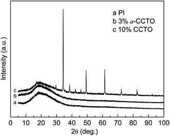 | ||
| Fig. 1 X-ray diffraction spectra of pure PI, the 3 vol% a-CCTO/PI hybrid film and the 10 vol% CCTO/PI hybrid film. | ||
Fig. 2 shows SEM images of fresh fractured cross-sections of the films. Fig. 2a shows the microstructure of the a-CCTO/PI hybrid film with 3 vol% concentration, and it shows that the PI matrix forms a continuous phase. The a-CCTO particles are less than 50 nm in size, and are dispersed relatively homogeneously because of the low doping concentration. The particles seem to grow on the PI matrix, which results in interfacial polarization occurring easily. For comparison, Fig. 2b shows the microstructure of the CCTO/PI hybrid film at a 10 vol% concentration. It can be found that CCTO particles of 2–3 μm are dispersed in the PI matrix. Local accumulation occurs because of the higher concentration and, therefore, the continuity of the PI matrix is slightly degraded. CCTO particle accumulation may also result from the sintering process of the ceramic powders, and consequently an internal barrier layer capacitance (IBLC) structure composed of conducting grains and insulating grain boundaries may be generated. The dielectric mechanism of the CCTO/PI film may be attributed to the high dielectric permittivity of CCTO.3 Additionally, CCTO is in a crystalline state and has marked characteristics such as anisotropy, observed in the polygon geometry. As a-CCTO is isotropic, its morphology is markedly different than that of CCTO.
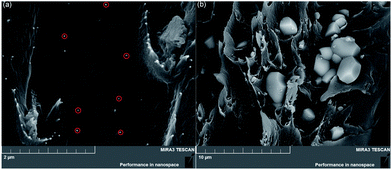 | ||
| Fig. 2 SEM morphology of freshly fractured cross-sections of (a) the 3 vol% a-CCTO/PI hybrid film, and (b) the 10 vol% CCTO/PI hybrid film. (Some nanoparticles are labeled with red circles). | ||
3.2 Dielectric properties of the a-CCTO/PI and CCTO/PI hybrid films
The dependence of the dielectric permittivity of the a-CCTO/PI hybrid films on frequency at room temperature is shown in Fig. 3. We found that the dielectric permittivity is 4.4 when the concentration of the a-CCTO filler is 3 vol% at 100 Hz, which is higher than that of PI (3.4) and CCTO/PI (3.8) when the concentration of CCTO filler is 10 vol%. We also found that the permittivity of the a-CCTO/PI films at the low concentration of 3 vol% is almost unchanged with an increase in the frequency. For the a-CCTO/PI film at 10 vol%, the permittivity decreases dramatically with an increase in frequency, and it was found to be 5.9 at 100 Hz, which is 74% higher than that of pure PI. This increase is higher than that in most reports.3,8,9,16 However, the decrease of permittivity is not remarkable compared with that of composites with conductive fillers.23–25 This indicates that the a-CCTO ceramic is semiconducting. The dielectric properties of the a-CCTO/PI hybrid films come from interfacial polarization relaxation, as shown in Fig. 4. For the a-CCTO/PI films, a dielectric loss peak is clear in the low frequency region, which is a characteristic frequency of space charge polarization. The relaxation peak is more obvious at 10 vol%, and this shows that the higher concentration contributes to the more active interface. No clear relaxation peak is present in the low frequency region for the CCTO/PI film. Fig. 5 shows that when the a-CCTO concentration is 3 vol%, the conductivity of the a-CCTO/PI hybrid film is only 2 × 10⁻¹⁰ S m−1 at 100 Hz and room temperature, which is close to that of the CCTO/PI film at 10 vol%. When the doping concentration of the a-CCTO/PI film is 10 vol%, the conductivity is 1 × 10⁻⁹ S m−1 at 100 Hz, which confirms that no conductive network was formed. This shows the good insulation performance of these films.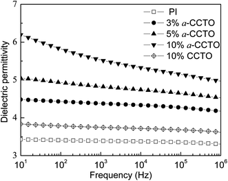 | ||
| Fig. 3 Dependence of dielectric permittivity on frequency for the a-CCTO/PI and CCTO/PI hybrid films at various volume fractions and at room temperature. | ||
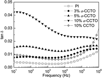 | ||
Fig. 4 Dependence of tan![[thin space (1/6-em)]](https://www.rsc.org/images/entities/char_2009.gif) δ on frequency for the a-CCTO/PI and CCTO/PI hybrid films at various volume fractions and at room temperature. δ on frequency for the a-CCTO/PI and CCTO/PI hybrid films at various volume fractions and at room temperature. | ||
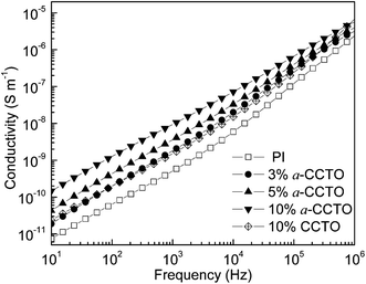 | ||
| Fig. 5 Dependence of conductivity on frequency for the a-CCTO/PI and CCTO/PI hybrid films at various volume fractions and at room temperature. | ||
Fig. 6 shows that the dielectric permittivity of the 3 vol% and 5 vol% a-CCTO/PI hybrid films decreases slightly with an increase in temperature at 100 Hz, and increases slightly for the 10 vol% film. At lower temperatures, the dielectric phenomenon can be attributed to interfacial polarization relaxation, as shown in Fig. 7, where the clear loss peak at low temperature is caused by interfacial polarization because the temperature is far less than the Tg of PI. This indicates that the segmental mobility of the polymer does not contribute to the permittivity. In Fig. 8, the conductivity at low temperature is sensitive to temperature, indicating that free changes are active at the interface,4 which is the second piece of evidence for interfacial polarization. For the high temperature 10 vol% a-CCTO/PI film, the higher dielectric permittivity mainly comes from the change in conductivity, as shown in Fig. 7 and 8, the dielectric loss and conductivity increase simultaneously with temperature at high temperature.7 The increase of conductivity and loss at high temperature has been observed in many previous reports.3,4,9,16,26 The conductivity of a-CCTO increases with increasing temperature,3 so the conductivity of the composites also increases with increasing temperature, and the increase is obvious when the doping concentration is large. The loss of the composites commonly increases with temperature at high temperature, and one reason for this is the ionic conductivity of the fillers.27 a-CCTO is characterized by impurity ions, defects and vacancies, etc. So the film has a higher loss at high temperature, while at low concentrations (3 and 5 vol%) the increase of conductivity and loss are not observed due to the low concentration of CCTO particles. In addition, the characteristic peak caused by interfacial polarization is so strong at low temperature that we cannot observe the increase of conductivity and loss at low concentration. For the CCTO/PI film, the interfacial polarization at low temperature is not obvious and the loss peak at high temperature may also be attributed to a conductivity change.
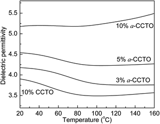 | ||
| Fig. 6 Dependence of dielectric permittivity on temperature for the a-CCTO/PI and CCTO/PI hybrid films at various volume fractions and at 100 Hz. | ||
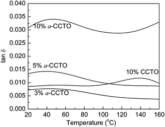 | ||
Fig. 7 Dependence of tan![[thin space (1/6-em)]](https://www.rsc.org/images/entities/char_2009.gif) δ on temperature for the a-CCTO/PI and CCTO/PI hybrid films at various volume fractions and at 100 Hz. δ on temperature for the a-CCTO/PI and CCTO/PI hybrid films at various volume fractions and at 100 Hz. | ||
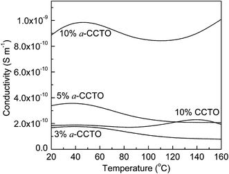 | ||
| Fig. 8 Dependence of conductivity on temperature for the a-CCTO/PI and CCTO/PI hybrid films at various volume fractions and at 100 Hz. | ||
3.3 Interface activation energy analysis of the a-CCTO/PI and CCTO/PI hybrid films
To further demonstrate that interfacial polarization exists in the a-CCTO/PI hybrid films, the activation energy (Ea) of the hybrid films was calculated. According to the Arrhenius law the conductivity is strongly dependent on temperature, and the equation can be written as:where σ0 is a pre-exponential term and represents the high temperature limit of conductivity, while k and T are the Boltzmann constant and the absolute temperature, respectively.
Fig. 9 shows the dependence of ln![[thin space (1/6-em)]](https://www.rsc.org/images/entities/char_2009.gif) σ for the a-CCTO/PI and CCTO/PI hybrid films on 1/T at 100 Hz. It was found that the majority of points are in accord with the linear fitting apart from a few points, and every curve over the whole range was fitted to a straight line. As shown in Fig. 9, the calculated Ea of the a-CCTO/PI hybrid films is negative and that of the CCTO/PI hybrid film is positive, which indicates that a large number of electrons are present at the interface of the a-CCTO/PI films. Therefore, interfacial polarization is easily realized. However, the positive activation energy implies that the movement of electrons is restricted in the CCTO/PI film. This verifies that the conductivity of the 3 vol% a-CCTO/PI film is close to that of the 10 vol% CCTO/PI film, as shown in Fig. 5.
σ for the a-CCTO/PI and CCTO/PI hybrid films on 1/T at 100 Hz. It was found that the majority of points are in accord with the linear fitting apart from a few points, and every curve over the whole range was fitted to a straight line. As shown in Fig. 9, the calculated Ea of the a-CCTO/PI hybrid films is negative and that of the CCTO/PI hybrid film is positive, which indicates that a large number of electrons are present at the interface of the a-CCTO/PI films. Therefore, interfacial polarization is easily realized. However, the positive activation energy implies that the movement of electrons is restricted in the CCTO/PI film. This verifies that the conductivity of the 3 vol% a-CCTO/PI film is close to that of the 10 vol% CCTO/PI film, as shown in Fig. 5.
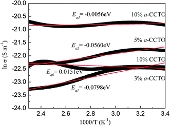 | ||
Fig. 9 Dependence of ln![[thin space (1/6-em)]](https://www.rsc.org/images/entities/char_2009.gif) σ on temperature for the a-CCTO/PI and CCTO/PI hybrid films at various volume fractions and at 100 Hz. σ on temperature for the a-CCTO/PI and CCTO/PI hybrid films at various volume fractions and at 100 Hz. | ||
a-CCTO ceramics were prepared using sol–gel technology. The gel powders were sintered at 300 °C to remove organic impurities. We found that nanosized particles could be prepared with ease. The nanosized a-CCTO was characterized by structural defects, impurity ions, vacancies and high defect densities because of the large surface area of the nanosized particles, which are the origin of space charges. The free charges available at the interface move easily when an electric field is applied. Ea represents the required energy per mole of electrons to activate these electrons. Negative Ea indicates that the electrons are already activated. Fig. 9 shows that |Ea1| > |Ea2| > |Ea3|, indicating that the amount of activated electrons (per mole) of the 3 vol% film is more than that of the 10 vol% film. Nanosized particles have a higher surface energy and tend to form agglomerates. For the higher concentration 10 vol% film, the agglomeration is more pronounced than for the 3 vol% film, resulting in a decrease in the number of activated electrons per mole, but the total number of activated electrons is still more than that of the 3 vol% film. The interfacial area of the composites can assess the interfacial effect quantitatively. Based on previous reports,4 we calculated the interfacial area in 1 m2 area of the films. As shown in Table 1, the interfacial area of the 3 vol% a-CCTO/PI film is 0.86 × 10⁶ m2, which is higher than that of the CCTO/PI film with 10 vol% (0.14 × 10⁶ m2). This indicates that the a-CCTO/PI film with 3 vol% has a higher polarized area and inherently possesses a higher permittivity than the CCTO/PI film with 10 vol%.
| Sample | Interfacial area (m2) |
|---|---|
| a-CCTO (3 vol%) | 0.86 × 10⁶ |
| a-CCTO (5 vol%) | 1.63 × 10⁶ |
| a-CCTO (10 vol%) | 4.16 × 10⁶ |
| CCTO (10 vol%) | 0.14 × 10⁶ |
4. Conclusions
In conclusion, a-CCTO/PI hybrid films with the desired dielectric permittivity at low concentrations were prepared by in situ polymerization, and the mechanical flexibility of pure PI was maintained. At a 3 vol% a-CCTO filler concentration, the dielectric permittivity was found to be 4.4 at 100 Hz, which is higher than that of the 10 vol% CCTO/PI hybrid film. The variation of the dielectric permittivity with temperature was slight and dielectric loss was low. In addition, the conductivity of the a-CCTO/PI films increases slowly with an increase in doping concentration, indicating a good insulating property. We also explored the dielectric mechanism of the a-CCTO/PI hybrid films. The higher dielectric permittivities of the a-CCTO/PI films compared with that of the CCTO/PI film reveal that the particles do not play a major role in the dielectric performance. The dielectric mechanism originates from interfacial polarization. The calculated Ea reveals that a large number of activated electrons are present at the active interface of the a-CCTO/PI films, and that electron motion at the interface of the CCTO/PI film is restricted. The reason for this is that nanosized particles with higher defect densities supply more space charges and, therefore, strong polarization at the interface is easily realized. Interfacial polarization relaxation is the main determinant of the properties of the a-CCTO/PI films, while the dielectric mechanism of the CCTO/PI film may be mainly attributed to the dielectric permittivity of CCTO. All the above-mentioned properties are beneficial for the use of a-CCTO/PI hybrid films in the electronics industry for applications such as printed circuit boards (PCBs).Acknowledgements
The authors gratefully acknowledge the support of the National Science Foundation of China (51202049), the Open Research Fund of State Key Lab of Electrical Insulation and Power Equipment (EIPE12205), the China Postdoctoral Science Foundation (2012T5037, 20110491097) and Science Funds for the Young Innovative Talents of HUST.Notes and references
- L. A. Fredin, Z. Li, M. A. Ratner, M. T. Lanagan and T. J. Marks, Adv. Mater., 2012, 24, 5946–5953 CrossRef CAS PubMed.
- Z. M. Dang, Y. Q. Lin, H. P. Xu, C. Y. Shi, S. T. Li and J. B. Bai, Adv. Funct. Mater., 2008, 18, 1509–1517 CrossRef CAS.
- Z. M. Dang, T. Zhou, S. H. Yao, J. H. Yuan, J. W. Zha, H. T. Song, J. Y. Li, Q. Chen, W. T. Yang and J. B. Bai, Adv. Mater., 2009, 21, 2077–2082 CrossRef CAS.
- W. H. Yang, S. H. Yu, R. Sun and R. X. Du, Acta Mater., 2011, 59, 5593–5602 CrossRef CAS PubMed.
- F. Amaral, C. P. L. Rubinger, F. Henry, L. C. Costa, M. A. Valente and A. B. Timmons, J. Non-Cryst. Solids, 2008, 354, 5321–5322 CrossRef CAS PubMed.
- S. Babu, K. Singh and A. Govindan, Appl. Phys. A: Mater. Sci. Process., 2012, 107, 697–700 CrossRef CAS.
- M. Arbatti, X. B. Shan and Z. Y. Cheng, Adv. Mater., 2007, 19, 1369–1372 CrossRef CAS.
- B. S. Prakash and K. B. R. Varma, Compos. Sci. Technol., 2007, 67, 2363–2368 CrossRef CAS PubMed.
- F. J. Wang, D. X. Zhou and Y. X. Hu, Phys. Status Solidi A, 2009, 206, 2632–2636 CrossRef CAS.
- R. Popielarz, C. K. Chiang, R. Nozaki and J. Obrzut, Macromolecules, 2001, 34, 5910–5915 CrossRef CAS.
- H. Windlass, P. M. Raj, D. Balaraman, S. K. Bhattacharya and R. R. Tummala, IEEE Trans. Adv. Packag., 2003, 26, 100–105 CrossRef CAS.
- Y. Bai, Z. Y. Cheng, V. Bharti, H. S. Xu and Q. M. Zhang, Appl. Phys. Lett., 2000, 76, 3804–3806 CrossRef CAS.
- M. A. Subramanian, D. Li, N. Duan, B. A. Reisner and A. W. Sleight, J. Solid State Chem., 2000, 151, 323–325 CrossRef CAS.
- L. Ni and X. M. Chen, J. Am. Ceram. Soc., 2010, 93, 184–189 CrossRef CAS.
- J. J. Romero, P. Leret, F. Rubio-Marcos, A. Quesada and J. F. Fernandez, J. Eur. Ceram. Soc., 2010, 30, 737–742 CrossRef CAS PubMed.
- P. Thomas, K. T. Varughese, K. Dwarakanath and K. B. R. Varma, Compos. Sci. Technol., 2010, 70, 539–545 CrossRef CAS PubMed.
- P. Thomas, K. Dwarakanath and K. B. R. Varma, Synth. Met., 2009, 159, 2128–2134 CrossRef CAS PubMed.
- L. J. Romasanta, P. Leret and L. Casaban, J. Mater. Chem., 2012, 22, 24705–24712 RSC.
- Y. Yang, B. P. Zhu, Z. H. Lu, Z. Y. Wang, C. L. Fei, D. Yin, R. Xiong, J. Shi, Q. G. Chi and Q. Q. Lei, Appl. Phys. Lett., 2013, 102, 042904 CrossRef.
- F. Y. Tsai, D. R. Harding, S. H. Chen and T. N. Blanton, Polymer, 2003, 44, 995–1001 CrossRef CAS.
- R. Murdey and J. T. Stuchless, J. Am. Chem. Soc., 2003, 125, 3995–3998 CrossRef CAS PubMed.
- C. Wang, Q. H. Wang and T. M. Wang, Langmuir, 2010, 26, 18357–18361 CrossRef CAS PubMed.
- F. He, S. T. Lau, H. L. Chan and J. T. Fan, Adv. Mater., 2009, 21, 710–715 CrossRef CAS.
- Z. M. Dang, L. Wang, Y. Lin, Q. Zhang and Q. Q. Lei, Adv. Mater., 2007, 19, 852–857 CrossRef CAS.
- Z. M. Dang, Y. H. Lin and C. W. Nan, Adv. Mater., 2003, 15, 1625–1629 CrossRef CAS.
- L. Zhang, X. B. Shan, P. X. Wu and Z. Y. Cheng, Appl. Phys. A: Mater. Sci. Process., 2012, 107, 597–602 CrossRef CAS.
- Y. Y. Sun, Z. Q. Zhang and C. P. Wong, Polymer, 2005, 46, 2297–2305 CrossRef CAS PubMed.
Footnote |
| † Electronic supplementary information (ESI) available. See DOI: 10.1039/c3tc31757a |
| This journal is © The Royal Society of Chemistry 2014 |

