Cross-linked and pH sensitive supported polymer bilayers from polymersomes – studies concerning thickness, rigidity and fluidity†
Jens
Gaitzsch
abc,
Dietmar
Appelhans
a,
Andreas
Janke
a,
Maria
Strempel
d,
Petra
Schwille
de and
Brigitte
Voit
*ab
aLeibniz-Institut für Polymerforschung Dresden e.V., Hohe Straße 6, 01069 Dresden, Germany. E-mail: voit@ipfdd.de
bOrganic Chemistry of Polymers, Technische Universität Dresden, 01062 Dresden, Germany
cDepartment of Chemistry, University College London, 20 Gordon Street, London WC1H 0AJ, UK
dTechnische Universität Dresden, Biotechnological Center, Tatzberg 47-49, 01307 Dresden, Germany
eMPI of Biochemistry, Am Klopferspitz 18, 82152 Martinsried, Germany
First published on 10th October 2013
Abstract
Polymersomes are at the leading edge of biomedical and nanoparticle research. In order to get closer insights into their mechanical properties, the bilayer forming them needs to be studied thoroughly. Here, we report on the bilayer formation, swelling behaviour, rigidity and fluidity of our membranes derived from pH sensitive and photo-cross-linkable polymersomes.
Introduction
Among the key features of all natural processes is the formation of specialized compartments for separate reactions.1,2 In nature, these compartments are formed of amphiphilic lipids and are thus called liposomes.3,4 Similar vesicles can also be formed by amphiphilic block copolymers. In accordance with their natural role model, they are called polymersomes.5–9 While possible applications of these synthetic vesicles as drug-delivery systems9–13 or synthetic nanoreactors14–18 are widely studied, their polymeric membrane itself has so far not been in the main focus of research. Due to the differences in molecule length and constitution, it can be suspected that polymeric membranes have substantially different properties than lipid membranes. It is already well known that polymersomes show an increased mechanical stability over liposomes, including a reduced diffusion across the membrane.5,19,20 However, fine-tuning this strength to allow diffusion of certain molecules is a major issue in current polymersome studies. This goal can be achieved by integrating proteins into a membrane21–24 of non-functionalized polymers or by the use of sensitive or cross-linkable polymers (or both) to get responsive vesicles.8,16,25–28 In this respect, responsive polymers are applied specifically to open up or destroy the vesicles upon e.g. a switch in pH or temperature.27,29,30 In contrast to polymersomes of non-responsive polymers, the mechanical properties are in that case specifically altered to reach a change in polymersome properties, e.g. higher permeability or leakiness. However, these changes were only monitored due to macroscopic changes of the polymersome properties, while a detailed study of the responsive membrane itself was not conducted.Besides the lack in studies of responsive membranes, their non-responsive counterparts (containing polystyrene (PS) and poly(dimethylsiloxane)(PDMS)) were studied with atomic force microscopy (AFM).31 It was thus consequent to conduct similar studies with our pH-sensitive and cross-linkable polymersome system.16,25,32 While the properties should be similar in a native state, they could now be altered and fine-tuned due to the characteristic pH dependent swelling–deswelling behaviour of our polymersomes. In our previous studies, we were already able to show that polymersome permeability, its ability to withstand shear forces, and even its biocompatibility could be adjusted and fine-tuned using pH and cross-linking density.16,32 It was therefore of interest whether the basic properties of the bilayer itself were dependent on the same parameters. Besides membrane thickness, we also studied the elastic modulus (E-modulus) and membrane fluidity. We expected great differences in membrane height upon acidification and a significant hardening upon cross-linking. It was not sure, however, how fluid the membrane would be in a native, i.e., non-cross-linked state.
Materials and methods
Polymer synthesis
The polymer (Fig. 1a) was synthesized as described previously16,25 (see also ESI†). At first, the imide-based cross-linker was synthesized within two steps to give the methacrylate derivative. The final polymer was then synthesized starting from the PEG–Br macroinitiator, which was accessible in one step from pure PEG. Both monomers of the second block (DEAEM and DMIBM) were added in a 5![[thin space (1/6-em)]](https://www.rsc.org/images/entities/char_2009.gif) :1 ratio and to give 90 monomers for each PEG–Br macroinitiator using standard ATRP conditions. The final block copolymer had the composition mentioned in the main text with a dispersity of 1.32 and a molar mass of 22.5 kDa.
:1 ratio and to give 90 monomers for each PEG–Br macroinitiator using standard ATRP conditions. The final block copolymer had the composition mentioned in the main text with a dispersity of 1.32 and a molar mass of 22.5 kDa.
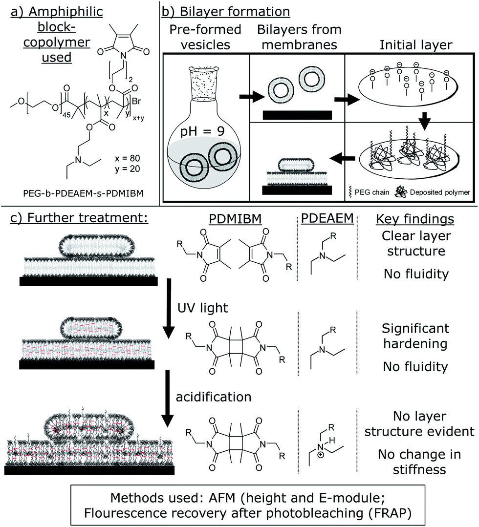 | ||
| Fig. 1 (a) Amphiphilic block copolymer used [poly(diethyl aminoethyl methacrylate) = PDEAEM for pH sensitivity; poly(3,4-dimethyl maleic imidobutyl methacrylate) = PDMIBM for cross-linking]; (b) formation of the polymer bilayer. The preformed vesicles are adsorbed on a plasma-cleaned surface, where an initial polymer layer is formed to support the following bilayer formation; (c) the deposited membrane can now be cross-linked and acidified, leading to changes in the physical properties (right). | ||
All further experiments were carried out at room temperature. The stock solutions of the pH values stated were prepared by adding 0.1 M HCl or 0.1 M NaOH stock solution to deionized water.
Atomic force microscopy (image analysis by WSxM33)
The films for this study were prepared from pre-formed polymersomes, which were prepared as described above. Si wafers of 1.0 cm2 were plasma-cleaned for 120 seconds and fortified using two-side glue tape. Now, 2 ml of the polymersome solution were added onto the Si wafer and after waiting for 15 s small spots for height evaluation were obtained (20 s for samples bound for acidification), while 30 s incubation time was used for samples for E-modulus determination. After the time elapsed, the polymersome solution was removed and aqueous pH 9 solution was added. Just before the AFM measurements the pH 9 solution was renewed again for basic samples. For acidic samples, the pH 9 solution was removed and an aqueous pH 5 solution was added. The AFM measurements were conducted in peak force tapping (heights)/quantitative nanomechanical analysis (E-modulus) mode. The E-modulus was calculated with an internal algorithm using a Derjaguin–Müller–Toporov model (modified Hertz model).Fluorescence recovery after photobleaching (FRAP)
The films for this study were prepared from pre-formed polymersomes, which were prepared as described above. Glass cover slides of 1.5 cm2 were plasma-cleaned for 120 seconds and equipped with 0.5 ml tubes by gluing (ground space approximately 0.25 cm2). Now, 200 μl of the polymersome solution were added onto the glass slide and incubated for the time mentioned in the main text. After the time elapsed, the polymersome solution was removed and pH 9 solution was added. For staining reasons, 1 μl of the Atto 647N stock solution (0.01 mg ml−1 in methanol) was added afterwards. The basic solution containing the staining was removed after 20 minutes and the solution was washed 3 times with pH 9 water. After the third wash, 200 μl of aqueous dye solution at pH 9 was added and the pictures were taken. For FRAP measurements, a certain area was bleached using a 633 nm laser and the final pictures were taken using a reading spectrum of <650 nm after the beam splitter. Now, images were taken every 60 s. For cross-linking, the sample was placed in the UV spot curing system mentioned above and irradiated for 60 s. After irradiation, FRAP was repeated as previously mentioned. Acidification was reached by removing the solvent and adding water with pH 5. The solution was removed and 200 μl of pH 5 solution were again added. FRAP was repeated as previously mentioned.Results and discussion
The polymer used in this study is the same as we used previously16,25 (Fig. 1) for the preparation of pH sensitive and photo-cross-linked polymersomes. Hence, we used a block copolymer prepared in an ATRP process with poly(ethylene glycol) (PEG) as a hydrophilic component and a statistical mixture of two components in the hydrophobic part. For once, poly(diethyl aminoethyl methacrylate) (PDEAEM) provides pH sensitivity and 20 mol% of poly(3,4-dimethyl maleic imidobutyl methacrylate) (PDMIBM, C4 polymers) as a photo-cross-linkable unit. Finally, the polymer can be written as PEG45-b-PDEAEM80-s-PDMIBM20 to represent its structure in Fig. 1.As shown previously, this polymer with this specific block length ratio forms polymersomes using a pH switch method,25,34 which are photo-cross-linked after 30 s of UV irradiation.16 For this work, the vesicles needed to be transformed into films of a single supported bilayer or multiple bilayers supporting each other. These supported bilayers were now characterized by AFM to yield the bilayer thickness and the E-modulus of the bilayer on a solid substrate. Additionally, fluorescence microscopy allowed assessing the fluidity of the membrane, i.e., how mobile the single polymer chains are. Since all measurements can be taken for the native bilayer as well as for the cross-linked and eventually acidified membrane, this study promises various results of which the most important ones are comprised in Fig. 1.
A large number of biophysical protocols are usually available from lipid membranes, which can be easily adapted due to the structural similarity (vesicle formed by a bilayer of amphiphilic molecules). This accounts also for the supported bilayers, which are a popular model system in membrane biophysics.35–37 A standard preparation method is to form supported bilayers from pre-formed vesicles on plasma-cleaned surfaces.36 It was thus an obvious strategy to employ the same approach for our polymersomes.
The polymersome production was not altered for the preparation of supported bilayers. Again, the single polymer was dissolved at pH 2 and any dust or non-dissolved residue was removed by a filtration step. Then vesicle self-assembly was induced by a pH change to a value of 9 to 10. It was now important to provide an energetic reason for the vesicles to abandon their stable shape and form a bilayer. A plasma-cleaned silica surface (e.g. SiO2 surface of a Si wafer) is a commonly used substrate for polymer films and was also used here. The plasma cleaning removes any residual organic matter from the surface and imparts a slightly negative charge onto it. Since the surface of the Si wafer consists of a thin layer of oxidized silicon, partially deprotonated oxygen atoms on the surface are present for a short time after the cleaning procedure. These charges now attract anything which is positively charged. At this point, the pH sensitive part of the polymer comes into play again. Although mainly deprotonated, enough charge may remain in order to induce the formation of a single polymer layer, thus inducing the so-called vesicle spreading (Fig. 1). Once the vesicles open up and form an initial layer, the surface is now covered with single polymer chains, due to the positive charges in the hydrophobic part of the polymer. The residual part of the polymer chain, the hydrophilic PEG part, should not show a distinct interaction with the Si wafer surface and is likely to point into the solution (Fig. 1). However, this initial layer is not a bilayer and not the goal of the procedure. Once created though, it gives support for a polymer bilayer to be formed. Any vesicle surface can now interact with the PEG chains present on the surface and intertwine with them. This kind of interaction can cause the vesicles to open up and form the desired polymer bilayer. Such a bilayer is now called a tethered bilayer.37–39 It is quite likely that the initial polymer layer is too thin to be detectable (and not shown in the bilayer-figures), but it is a necessary precondition. While this explains the formation of the first bilayer, the formation of eventual additional bilayers of the polymer membrane, which are likely to be formed, has to be discussed independently. The reason for this behaviour is the solubility behaviour of PEG. Although it is water soluble, it contains two methylene units and only one hydrophilic oxygen atom in each repeating unit. Hence, it is likely that hydrophilic PEG–PEG interactions are energetically favoured over hydrophilic PEG–water interactions, as known from the literature.40 As the initial polymer bilayer is formed, the outer PEG chains of the remaining polymersomes have the chance to interact and entangle with the PEG groups on the surface. Once there, the vesicles can now spread onto the preformed bilayer, forming the second bilayer on the top of it. Logically, this process can be continued from the top, if possible, forming multiple bilayers of different heights. As an ideal method to prove this theory and eventually analyse the bilayer structure, AFM was chosen.
However, before determining the height of the polymer bilayer, it is more important to prove that the structures present are in fact a result of the polymersomes. Ideally, the membranes dissolve and leave the Si wafer surface, once the solution is acidified (Fig. 2). Now, the pH sensitive part of the polymer gets protonated and the whole polymer becomes water soluble. The same force which causes the polymersomes to disassemble, the repellence of the positive charges in the PDEAEM+, should now force the non-cross-linked deposited bilayer to leave the surface. This is proven by comparing AFM images at pH = 9 and pH = 4 (Fig. 2). As clearly visible, numerous spots, i.e., possible spread vesicles, are visible on the AFM image taken under basic conditions (Fig. 2). In contrast, virtually no spots can be detected on the AFM image taken at pH 4. Now all polymer chains, also the first monolayer, left the surface due to the reasons discussed above. This result clearly shows that the deposited material was spread polymersomes (as indicated in Fig. 2) and now allows for further bilayer analysis in a wet state. Since any shear rate might affect the bilayer properties, no flow cell was used, but the bilayers were examined in a steady solution on top of the Si wafer.
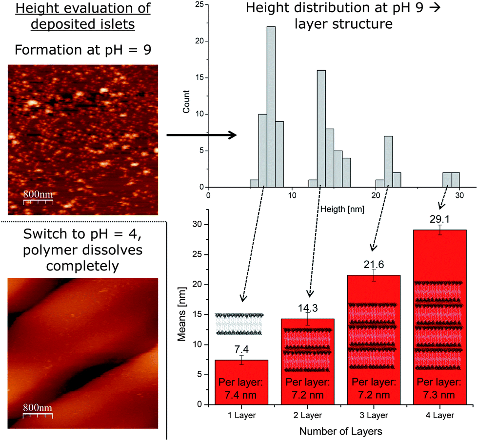 | ||
| Fig. 2 AFM images of the hydrated deposited polymer bilayer membrane (top) and the corresponding image after acidification (bottom). The image under basic conditions is evaluated by height in a histogram (top). An analysis of the clearly distinguishable peaks yields a bilayer-by-bilayer structure from one to four bilayers, which also reveals the average height of the individual bilayers deposited (bottom). | ||
The most obvious characteristic of a freshly deposited bilayer is its thickness, which was consequently addressed first (Fig. 2). Besides the height of the single bilayer, a step-wise increase of heights would prove the bilayer-by-bilayer growth as proposed earlier. Before being cross-linked, i.e. in a basic state, we scanned the structures on the Si wafer using AFM in solution. While the tip scans the surface, it eventually reveals various bilayers of spread vesicles on the Si wafer surface. Now the heights of randomly chosen spots of spread vesicles were measured and the corresponding height profiles were recorded (Fig. 2). In order to reach the actual height of a spot, great emphasis was put upon finding the actual top of the spots. From each profile, the peak height was recorded. This procedure was repeated numerous times in independent experiments for statistical significance. After a substantial number of peak heights were collected, they were sorted and plotted by size (histogram, see Fig. 2). This plot revealed a remarkable property of the spread polymersomes. It shows a separation into individual groups of equally distanced heights. Between 5 and 10 nm the first peak in the distribution is obvious, followed by a gap. The very same behaviour repeats itself another two times in the histogram-evaluation. After the second peak in the distribution at 15 nm, a gap follows before the consecutive maximum at 22 nm is determinable. Again, a gap can be seen afterwards until the last group of heights just below 30 nm.
The first maximum should represent the thickness of a single supported bilayer present on the surface. Each of the following groups of heights then represents another bilayer deposited on the first one. Single deposited monolayers are not observed, since the hydrophobic PDEAEM would then be in contact with water, which is energetically far less favoured than an interaction with another hydrophobic PDEAEM part of the next layer. This assumption is in total agreement with the numeric height values of each bilayer, which increase by just over 7 nm each time. Additionally, it also shows that the initial polymer layer supporting the tethered bilayer is not detectable. Theoretically, each new bilayer should occur less frequently than the previous one (histogram, see Fig. 2). The decreasing number of heights with every new bilayer totally agrees with this hypothesis and supports the assumption of stepwise bilayer deposition. Apparently, not all single bilayer spots are covered by a second one. This reduces the surface of two-bilayered films and hence also the probability for a third bilayer to form. Consequently, each new bilayer is less likely to be found than the previous one. Additionally, the bar chart evaluation (see Fig. 2) also revealed small values of standard deviation for each bilayer, which again supported the assumption of a bilayer-by-bilayer deposition of polymersomes. In sum, all bilayer data support the theory that a first bilayer of spread polymersomes can act as a substrate for a further bilayer to deposit, an assumption, which goes along with the recent literature.31
It was also of interest whether additional bilayers would compress lower bilayers. If a compression would happen, the average height would decrease with increasing bilayer thickness. However, a comparison of the average height for one, two, three and four bilayers does not suggest that. The initial decrease from 7.4 nm thickness to an average of 7.2 nm for two bilayers is within experimental error and did not continue for further bilayers (see Fig. 2). In the case of four polymer bilayers upon each other, the average height determined (7.3 nm) remained constant, essentially ruling out that compression is occurring.
The key feature of the polymersomes created is the combination of pH sensitivity and cross-linking, a combination, which resulted in the defined reproducible swelling–deswelling behaviour of the polymersomes.16 Of course, the swelling should also be notable within the deposited membrane. Hence, we studied the acidified membrane also with AFM to obtain the membrane height as well as a possible bilayer-by-bilayer structure.
Our initial interest was whether the bilayers produced would remain on the Si wafer. As previously mentioned, non-cross-linked polymer bilayers simply dissolve upon acidification (Fig. 2). Hence, the adhesive force between the PEG parts and the Si wafer surface is not high enough to prevent detachment of the single polymer chains under acidic conditions. This behaviour changed completely after cross-linking the membranes. After 30 s and 60 s of UV irradiation (high pressure mercury lamp) with consecutive acidification, patches of polymer bilayers were detected (Fig. 3). Unlike their non-cross-linked precursor, the cross-linked polymersome patches now stick to the surface tightly enough to prevent detachment. An evaluation of the height of the patches reveals an interesting change under basic conditions. While a bilayer-by-bilayer structure could be observed under basic conditions, no such explicit structure could be determined in an acidic state. Here, an almost continuous range of heights could be detected for the conditions tested (Fig. 3). Again, structures of lower height were more frequently determined than larger ones. However, the histogram evaluation of 30 s and 60 s UV irradiation suggests the presence of the second bilayer after the obvious initial one (Fig. 3). Although low in intensity, an additional peak may be suspected at 50 nm, just after the initial one at around 25 nm. A thickness of each swollen bilayer of about 25 nm would mean a rise by 3.5 times compared to the height under basic conditions. This rise seems quite high compared to results discovered by TEM (rise to 1.5 times of the original height).16 TEM, however, does not consider the PEG corona, which may lead to the difference mentioned. Being able to detect the second bilayer, however, indicates the stability of the multi-bilayer structure.
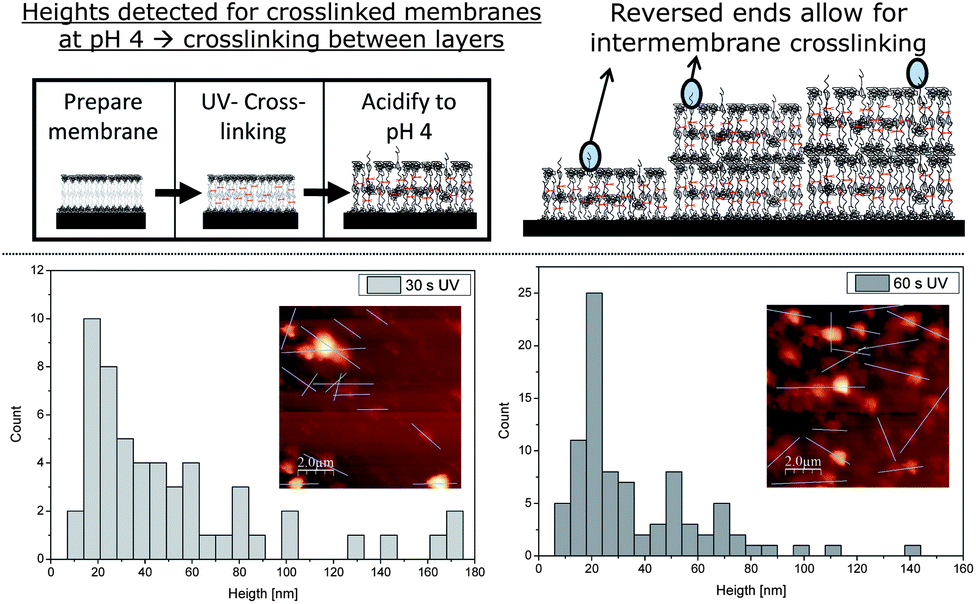 | ||
| Fig. 3 The deposited membranes were cross-linked and subsequently acidified. The samples were studied with AFM after 30 s and 60 s of UV irradiation and the corresponding histograms of the heights produced. The absence of the obvious bilayer structure and the presence of several bilayers can be explained by inter-membrane cross-linking due to reversed polymer chains. | ||
Besides the thickness of one bilayer, the maximal heights recorded rose considerably as well. While a maximum of 29 nm was detected under basic conditions, the sizes now range up to 170 nm for 30 s and 140 nm for 60 s of UV irradiation. This corresponds to a rise in maximal height of roughly 400% after acidification. Both maxima (140 and 170 nm) cannot result from a single polymer bilayer and thus show that the multiple bilayer structure must have been retained. Due to the protonation of each bilayer upon acidification, the bilayers repel each other under these conditions. Not showing detachment though, it is a clear sign of cross-linking between the bilayers. This phenomenon may be explained by an imperfect structure of the bilayer itself. There is a chance that not all polymers insert into the membrane in the desired way, but also in an inverse manner. This would lead to cross-linkable groups on the outside of the deposited polymer bilayer and consequently to inter-membrane cross-linking, if two membranes touch each other during UV irradiation (Fig. 3). Obviously, inter-membrane cross-linking cannot be as dense as intra-membrane cross-linking due to the lower amount of reactive groups available. Longer UV irradiation, however, should lead to a more dense cross-linking and thus, to a reduced swelling. However, this hypothesis is not significantly undermined by the experimental data. The heights obtained from films irradiated for 60 s are only slightly lower than the ones obtained after 30 s of UV irradiation and similar conditions otherwise and the differences are within the experimental error. Both irradiation times, however, prove that inter- and intra-membrane cross-linking occurs for the deposited bilayers, due to high height values detected in both cases (Fig. 3).
Besides membrane height, AFM accesses membrane rigidity or their E-modulus, another important characteristic of bilayers.41,42 In this study, the E-modulus of bilayers was examined in various stages. Initially, non-cross-linked deposited bilayers were investigated. In consecutive studies, the procedure was repeated first for cross-linked films and finally for acidified cross-linked bilayers, while two cross-linking times (30 s and 60 s of UV irradiation) were examined. Thus, the influence of cross-linking bonds could be investigated, as well as the influence of acidification.
The bilayers used for this investigation were produced in the same way as the bilayers for height investigations. Again, the vesicles were spread on a plasma cleaned Si wafer surface. In contrast to previous investigations though, the films created needed to be of certain thickness and covering a larger area on the substrate. If the films are too thin, the AFM tip does not only measure the elasticity of the bilayer, but also partially that of the Si wafer surface which supports the bilayer – ultimately leading to a very high E-modulus. On the other hand, very thick bilayers lack the stability necessary to access the E-modulus of the film. Another prerequisite, a sufficient diameter of the spots, is important to reduce edge effects. In the end, the correct value can only be determined if the area to be probed by the AFM tip reacts like a surface of indefinite dimension as described by the Hertz model,43 the applied model to determine the E-modulus by the AFM software used. In addition, the problem of a missing calibration of the tip and its possible loss in quality over various measurements has to be considered. In the end, the AFM always measures the bilayer spots, but also the plain Si-wafer surface next to the bilayers. Since the E-modulus of silicon is readily available in the literature, this value is chosen as a standard to calibrate each measurement. Due to this reason, the results are displayed as the difference of the determined E-modulus in comparison with the Si wafer surface.
For a reliable statistics, the E-modulus was recorded at least at 6 different spots and the mean value was determined. The result for a single bilayer (40 MPa) is in between the values for PDMS68-PMOXA11 and PS115-PAA15 membranes reported previously.31 We therefore think this result is reasonable for a polymer bilayer. As expected, the cross-linked membranes are stiffer (higher E-modulus). In the bar chart used for visualization (Fig. 4) a shorter bar means less difference to silicon, i.e., a harder material. The cross-linking bonds considerably strengthen the material, since they hinder the polymer chains from moving away from each other in response to an external force applied. Additionally, the previously discovered inter-membrane cross-linking also holds the different bilayers in place. Hence, the bilayers cannot move independently from each other anymore, again resulting in greater stiffness of the material. Interestingly, the initial effect of cross-linking is stronger than the effect of UV irradiation. While both membranes, UV irradiated for 30 and 60 s, show significant hardening compared to their non-cross-linked counterpart (statistical relevance of >99.9% according to the t-test), the cross-linked samples show no significant difference between one another.
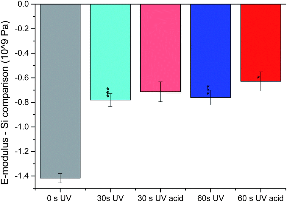 | ||
| Fig. 4 Measuring the E-modulus using AFM in a wet state. The graph shows the change in the exponent of the E-modulus in comparison with the plain Si wafer surface. The grey bar is for the non-cross-linked membrane, the blue ones for cross-linked ones (30 s and 60 s) and red ones after acidification. The statistical tests on the cross-linked membranes refer to the non-cross-linked one and the tests on the acidified ones refer to their basic counterparts. | ||
One of the most interesting results from the swelling experiments was the ability to detect multiple layers under acidic conditions after cross-linking. As their basic analogues, the swollen membranes were now probed for their E-modulus. Surprisingly, only a small change towards a less elastic material could be noticed in comparison with the non-swollen cross-linked membranes. Only for 60 s of UV irradiation, a notable change with >95% significance (according to the t-test) towards a higher E-modulus was detected (Fig. 4). It may be suspected that this result is a combination of two antagonistic effects. For once, the swelling is due to a substantial uptake of water. Being above 0 °C, the membrane should lose stiffness and move around more easily. Once solvated, the polymer chains only have the solvent water to hinder their movements and no bulky polymer chains any more. With increasing cross-linking density, the degree of movement decreases and the described effect becomes smaller. On the other hand, the membrane swells in order to get as much distance as possible between the positive charges present under acidic conditions. If the membrane is to be moved in this state, the repelling force between the positive charges has to be overcome. Logically, overcoming a repelling force hardens the material. Furthermore, increasing the cross-linking density (and potentially less swelling) leaves less distance between the positive charges, yielding higher repelling forces between them. Hence, this effect becomes stronger with increasing cross-linking density. In the case studied here, both phenomena seem to be of equal strength for 30 s of UV irradiation, due to the lack of change in the E-modulus. Due to the tendency just described, the now significant hardening for 60 s of UV irradiation is in full accordance with the effects described.
In summary, it can be stated that cross-linking hardens the deposited membranes greatly, while consecutive acidification has a small or no effect at all.
The final aspect to be considered is the so-called fluidity of the membrane, which describes the mobility of the single molecules within the membrane.36 In order to detect this parameter, the deposited membrane described above needs to be large enough for the molecules to move around freely without being slowed down at the edge or inhomogeneous spots of the material. Besides the ability to have unhindered diffusion, the polymers need to be detected. Since non-labelled polymers were used in this work, another way to reach the necessary labelling had to be found. Here, physisorption of fluorescent molecules which move around with the polymer without influencing its properties was chosen. Being already used for lipid membranes, physisorbing a labelled lipid seemed reasonable. Although the dye–lipid combination used (Atto 647N-DOPE, structure not published by supplier) is of partial positive charge, they show physisorption onto the polymer bilayer. Since the hydrophobic part of the polymer is slightly positively charged, this behaviour was not guaranteed to occur. Due to the staining, the sizes of the polymer bilayer islets could be judged whether they were large enough for fluidity tests. For this reason, the polymersomes were allowed to spread on a plasma cleaned glass surface for 15 s, 30 s, 45 s, 60 s and 90 s and were labelled by physisorption of the fluorescence marker afterwards (see ESI†). Comparing all pictures it is clearly visible that the bilayers grow with longer incubation times. While incubating the surface for 15 s or 30 s yielded only small islets, a continuous bilayer developed after 60 s and 90 s incubation times. Since polymer membrane fluidity would only be influenced by very small islets but not by large ones, continuous films produced after 90 s incubation were used for further studies.
A well-known method to determine the fluidity from fluorescent images is FRAP.44 Here, a small section is bleached with a strong laser. If the membrane is fluid, the bleached area is re-filled with dye which diffuses in from non-bleached areas. For usual fluid lipid membranes, such a refill of the bleached area occurs within two to five minutes. Interestingly, for the polymer bilayer studied, no fluorescence recovery of the bleached area could be detected for at least 30 minutes (Fig. 5). Such a greatly non-fluid behaviour was not expected for a polymer bilayer, which was supposed to mimic a lipid bilayer. On the other hand, the lack of fluidity is another proof for the enhanced mechanical stability of polymersomes over liposomes. In fact, the typical entanglement of polymer chains is prone to reduce fluidity or stop it completely as detected here. Of course, cross-linking the polymer membrane bilayer decreases the mobility of the polymer chains even further and hence also of the physisorbed labelled lipid. Interestingly, the attached dye was still detectable after the cross-linking process and not bleached away. With the dye still present, the FRAP experiment was carried out at a cross-linked membrane and obtained the expected result of no mobility (Fig. 5). It was now not certain whether the previously physisorbed dye of partial positive charge would regain mobility in an acidified membrane, which is also of positive charge. The swollen membrane could give the lipid molecules space for diffusion through eventual pores forming within the acidified cross-linked polymer bilayer. However, the dye labelled lipid remained in place, but showed a loss in fluorescence intensity over time (Fig. 5), which is mainly due to the lack of photostability under acidic conditions of the Atto 647N used. Another reason for the loss of intensity detected may be that some lipids leave the membrane, due to the positive charges of the dye and the polymer repelling each other.
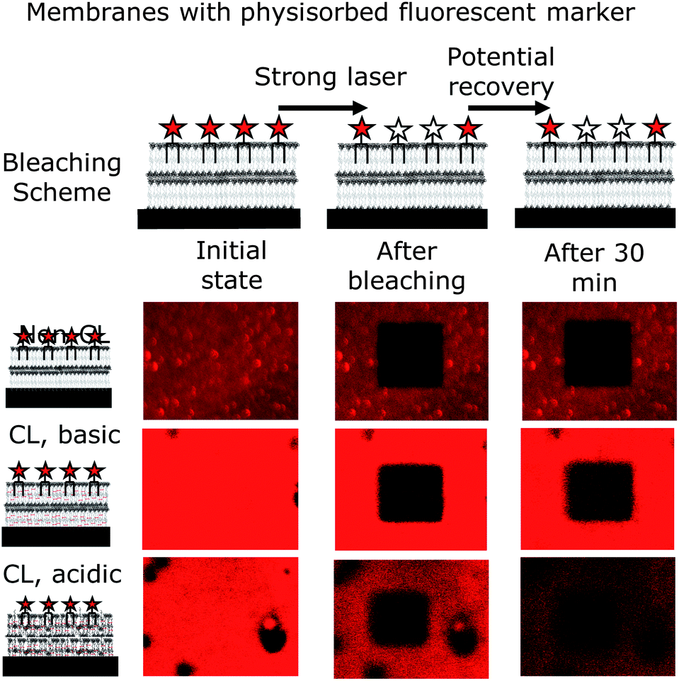 | ||
| Fig. 5 Fluidity of the membranes deposited tested via FRAP using a positively charged labelled lipid (Atto 647N-DOPE). For all conditions tested (non-cross-linked and cross-linked – basic and acidic), the membranes proved to be completely non-fluid. It is notable though that the dye used is not photostable under acidic conditions, and the bleached area (bleached with strong laser for 60 s) remains black (no recovery), showing the lack of dye movement for all conditions tested. | ||
Thus, none of the conditions resulted in a fluid nature of the membranes investigated. All, the non-cross-linked, the basic cross-linked and the acidic cross-linked membranes appeared to be completely non-fluid.
Conclusions
Here we presented the formation of single and multiple supported polymer bilayers from polymersomes, and their biophysical characterization. The formation could be performed on plasma-cleaned silicon and glass surfaces without the addition of further substances or any additional external force. By AFM analysis we were able to show that the polymersomes also adsorb on top of each other to produce additional bilayers. The resulting bilayer-by-bilayer structure showed a narrow distribution for each bilayer and an essentially equal height for each additional bilayer. The main characteristic of the polymersome system investigated is the combination of pH sensitivity and photo-cross-linking. The known ability of cross-linked polymersomes to show a definite swelling was to be translated onto the films generated. Interestingly, the films did show the same swelling, but the definite bilayer structure mentioned previously vanished, although the total height suggests the presence of multiple bilayers after acidification. Apparently, the different bilayers are held together despite the positive charges generated after acidification. It was not unreasonable to assume that protonated amino units in the PDEAEM part after acidification lead to repulsing forces between the bilayers, ultimately leading to their detachment. However, possible impurities in the membrane structure, like falsely inserted polymers, lead to inter-membrane cross-linking. These loose connections are different for every bilayer and thus lead to the loss of the clear bilayer-by-bilayer structure by different swelling levels for each spot examined.In addition to thickness, we also examined the E-modulus of the bilayers. Here, our findings for non-cross-linked polymersomes correspond to another polymersome-forming system were reported. As expected, cross-linking of the bilayers resulted in a significant rise of the E-modulus. However, a consecutive acidification of the bilayers did not lead to a significant hardening or softening of the material. Here, the repelling (hardening) forces of the positive charges and the softening due to the swelling neutralize each other to result in no overall change of the E-modulus.
In order to compare our system with lipid membranes, we also checked the fluidity of our supported polymer bilayer via the FRAP method. Interestingly, no significant diffusion could be observed for 30 minutes after bleaching. This demonstrates once again the increased mechanical strength of polymer membranes with respect to lipid ones, which show a complete recovery after 5 minutes or less.44,45
As we could show, an analysis of a deposited membrane yields direct access to key parameters like membrane thickness, hardness and fluidity. We are confident that our insights into polymeric bilayers form a solid basis for checking other polymersome forming systems also in this manner.
Acknowledgements
Financial support of the Rosa-Luxemburg-Foundation and the Dresden International Graduate School for Biomedicine and Bioengineering (DIGS-BB) is gratefully acknowledged.Notes and references
- C. LoPresti, H. Lomas, M. Massignani, T. Smart and G. Battaglia, J. Mater. Chem., 2009, 19(22), 3576–3590 RSC.
- J. W. Szostak, D. P. Bartel and P. L. Luisi, Nature, 2001, 409, 387–390 CrossRef CAS PubMed.
- P. Schwille, Science, 2011, 333, 1252–1254 CrossRef CAS PubMed.
- P. L. Luisi, P. Walde and T. Oberholzer, Curr. Opin. Colloid Interface Sci., 1999, 4, 33–39 CrossRef CAS.
- D. E. Discher, B. M. Discher, Y. Y. Won, D. S. Ege, J. C. M. Lee, F. S. Bates and D. A. Hammer, Science, 1999, 284, 1143–1146 CrossRef.
- D. E. Discher and A. Eisenberg, Science, 2002, 297, 967–973 CrossRef CAS PubMed.
- S. F. M. van Dongen, H. P. M. de Hoog, R. J. R. W. Peters, M. Nallani, R. J. M. Nolte and J. C. M. van Hest, Chem. Rev., 2009, 109, 6212–6274 CrossRef CAS PubMed.
- J. Gaitzsch, D. Appelhans and B. Voit, Nachr. Chem., 2012, 60, 1176–1180 CrossRef CAS.
- X. Huang and B. Voit, Polym. Chem., 2013, 4, 435–443 RSC.
- O. Onaca, R. Enea, D. W. Hughes and W. Meier, Macromol. Biosci., 2009, 9, 129–139 CrossRef CAS PubMed.
- E. Lallana, A. Sousa-Herves, F. Fernandez-Trillo, R. Riguera and E. Fernandez-Megia, Pharm. Res., 2012, 29, 1–34 CAS.
- J. S. Lee and J. Feijen, J. Controlled Release, 2012, 161, 473–483 CrossRef CAS PubMed.
- G. Wang, R. de Kruijff, M. C. A. Stuart, E. Mendes, H. T. Wolterbeek and A. G. Denkova, Soft Matter, 2013, 9, 727–734 RSC.
- K. Renggli, P. Baumann, K. Langowska, O. Onaca, N. Bruns and W. Meier, Adv. Funct. Mater., 2011, 21, 1241–1259 CrossRef CAS.
- H. De Oliveira, J. Thevenot and S. Lecommandoux, Wiley Interdiscip. Rev.: Nanomed. Nanobiotechnol., 2012, 4, 525–546 CrossRef CAS PubMed.
- J. Gaitzsch, D. Appelhans, L. G. Wang, G. Battaglia and B. Voit, Angew. Chem., Int. Ed., 2012, 51, 4448–4451 CrossRef CAS PubMed.
- M. Marguet, C. Bonduelle and S. Lecommandoux, Chem. Soc. Rev., 2013, 42, 512–529 RSC.
- A. Najer, D. L. Wu, D. Vasquez, C. G. Palivan and W. Meier, Nanomedicine, 2013, 8, 425–447 CrossRef CAS PubMed.
- J. F. Le Meins, A. C. Carlsen, N. Glaser and S. Lecommandoux, Langmuir, 2011, 27, 4884–4890 CrossRef PubMed.
- M. Schulz, D. Glatte, A. Meister, P. Scholtysek, A. Kerth, A. Blume, K. Bacia and W. H. Binder, Soft Matter, 2011, 7, 8100–8110 RSC.
- P. Tanner, S. Egli, V. Balasubramanian, O. Onaca, C. G. Palivan and W. Meier, FEBS J., 2011, 278, 32 Search PubMed.
- X. Y. Zhang, P. Tanner, A. Graff, C. G. Palivan and W. Meier, J. Polym. Sci., Part A: Polym. Chem., 2012, 50, 2293–2318 CrossRef CAS.
- D. M. Vriezema, P. M. L. Garcia, N. S. Oltra, N. S. Hatzakis, S. M. Kuiper, R. J. M. Nolte, A. E. Rowan and J. C. M. van Hest, Angew. Chem., Int. Ed., 2007, 46, 7378–7382 CrossRef CAS PubMed.
- S. F. M. van Dongen, M. Nallani, J. L. L. M. Cornelissen, R. J. M. Nolte and J. C. M. van Hest, Chem.–Eur. J., 2009, 15, 1107–1114 CrossRef CAS PubMed.
- J. Gaitzsch, D. Appelhans, D. Grafe, P. Schwille and B. Voit, Chem. Commun., 2011, 47, 3466–3468 RSC.
- S. Y. Yu, T. Azzam, I. Rouiller and A. Eisenberg, J. Am. Chem. Soc., 2009, 131, 10557–10566 CrossRef CAS PubMed.
- S. P. Hsu, I. M. Chu and J. D. Yang, J. Appl. Polym. Sci., 2012, 125, 133–144 CrossRef CAS.
- M. A. Yassin, D. Appelhans, R. G. Mendes, M. H. Rummeli and B. Voit, Chem.–Eur. J., 2012, 18, 12227–12231 CrossRef CAS PubMed.
- A. Blanazs, M. Massignani, G. Battaglia, S. P. Armes and A. J. Ryan, Adv. Funct. Mater., 2009, 19, 2906–2914 CrossRef CAS.
- I. Canton and G. Battaglia, Chem. Soc. Rev., 2012, 41, 2718–2739 RSC.
- K. Jaskiewicz, M. Makowski, M. Kappl, K. Landfester and A. Kroeger, Langmuir, 2012, 28, 12629–12636 CrossRef CAS PubMed.
- J. Gaitzsch, I. Canton, D. Appelhans, G. Battaglia and B. Voit, Biomacromolecules, 2012, 13, 4188–4195 CAS.
- I. Horcas, R. Fernandez, J. M. Gomez-Rodriguez, J. Colchero, J. Gomez-Herrero and A. M. Baro, Rev. Sci. Instrum., 2007, 78, 013705 CrossRef CAS PubMed.
- D. J. Adams, M. F. Butler and A. C. Weaver, Langmuir, 2006, 22, 4534–4540 CrossRef CAS PubMed.
- N. Kahya, D. Scherfeld, K. Bacia, B. Poolman and P. Schwille, J. Biol. Chem., 2003, 278, 28109–28115 CrossRef CAS PubMed.
- A. J. Garcia-Saez and P. Schwille, Biochim. Biophys. Acta, Biomembr., 2010, 1798, 766–776 CrossRef CAS PubMed.
- B. Wiltschi, W. Knoll and E. K. Sinner, Methods, 2006, 39, 134–146 CrossRef CAS PubMed.
- Y. R. Kim, S. Jung, H. Ryu, Y. E. Yoo, S. M. Kim and T. J. Jeon, Sensors, 2012, 12, 9530–9550 CrossRef CAS PubMed.
- W. Knoll, F. Yu, T. Neumann, S. Schiller and R. Naumann, Phys. Chem. Chem. Phys., 2003, 5, 5169–5175 RSC.
- M. Calderon, M. A. Quadir, S. K. Sharma and R. Haag, Adv. Mater., 2010, 22, 190–218 CrossRef CAS PubMed.
- H. J. Butt, B. Cappella and M. Kappl, Surf. Sci. Rep., 2005, 59, 1–152 CrossRef CAS PubMed.
- D. J. Muller and Y. F. Dufrene, Nat. Nanotechnol., 2008, 3, 261–269 CrossRef PubMed.
- H. Hertz, Journal für die reine und angewandte Mathematik, 1882, 92, 156–171 Search PubMed.
- G. Rayan, J. E. Guet, N. Taulier, F. Pincet and W. Urbach, Sensors, 2010, 10, 5927–5948 CrossRef PubMed.
- M. Tominaga, S. Kusano and N. Nakashima, Bioelectrochem. Bioenerg., 1997, 42, 59–62 CrossRef CAS.
Footnote |
| † Electronic supplementary information (ESI) available: Polymer synthesis in general and bilayer growth for FRAP. See DOI: 10.1039/c3sm52016a |
| This journal is © The Royal Society of Chemistry 2014 |