Mechanical bending properties of sodium titanate (Na2Ti3O7) nanowires†
Arixin Boa,
Haifei Zhanab,
John Bella,
Huaiyong Zhua and
Yuantong Gu*a
aSchool of Chemistry, Physics and Mechanical Engineering, Queensland University of Technology, GPO Box 2434, 4001, Brisbane, QLD, Australia. E-mail: yuantong.gu@qut.edu.au; Fax: +61-7-31381469; Tel: +61-7-31381009
bDepartment of Material Science and NanoEngineering, Rice University, Houston, TX 77005, USA
First published on 24th October 2014
Abstract
We report on the mechanical properties of sodium titanate nanowires (Na2Ti3O7 NW) through a combination of bending experiments and theoretical analysis. Na2Ti3O7 NWs with lateral dimensions ranging from 20–700 nm were synthesized by a hydrothermal approach. A focused ion beam (FIB) was used to manipulate the selected Na2Ti3O7 NW over a hole drilled in an indium tin oxide substrate. After welding the nanowire, a series of bending tests was performed. It was observed that the Na2Ti3O7 NW exhibits a brittle behavior, and a nonlinear elastic deformation was observed before failure. By using the modified Euler–Bernoulli beam theory, such nonlinear elastic deformation is found to originate from a combination of surface effects and axial elongation (arising from the bending deformation). The effective Young's modulus of the Na2Ti3O7 NW was found to be independent of the wire length, and ranges from 21.4 GPa to 45.5 GPa, with an average value of 33 ± 7 GPa. The yield strength of the Na2Ti3O7 NW is measured at 2.7 ± 0.7 GPa.
1. Introduction
Titanates are widely acknowledged as functional ceramic materials with attractive properties such as dielectric, piezoelectric and ferroelectric properties.1–4 They have been broadly used as structural reinforcements in polymers, metals, and ceramic composites.5,6 In the family of titanates, sodium titanates are emerging as materials of great interest for their novel applications in batteries,7,8 industrial liquid waste treatment,9 fuel-cell electrolyte10 and catalyst.11 In the field of Li batteries, Na-based technologies have drawn increasing attention due to the superior availability and potentially lower cost of the raw materials. In this regard, the sodium titanate has been shown to be a suitable material with favourable capacities.8 By changing the synthetic method, various external morphologies of sodium titanate can be obtained, including nanowires (NWs) and nanotubes9,12,13 and their internal structure can also be diversely altered.14,15 These features have made sodium titanate a strong candidate in a broad range of applications as functional material or as substrate.13,16–19 Nevertheless, to the best of our knowledge, the mechanical properties of Na2Ti3O7 material have not yet been revealed.Many studies have shown that tremendous benefits are brought to the performance of the devices by incorporating wire-like (high length to width ratio) nanomaterial structures. Taking NW batteries as an example, the major advantage of NWs, compared to their bulk counterparts, are their capability to overcome the well-known pulverization problem which is detrimental to the battery cycle life.20 NW adsorbents are also shown to be much easier to settle compared to bulk ion exchangers so that they can be efficiently recovered from the contaminant solutions.9 A NW-based pressure sensor has been reported to have greatly improved sensitivity and stability,21 compared to a similar pressure sensor fabricated from bulk materials. It is clear that the rapid development of NW materials has boosted the activities in nanotechnology and nanomechanics, to the extent that understanding of the mechanical properties of NWs has become extremely important. This is because understanding nanowire mechanical properties is essential for fabrication of devices such as nanocomposite strengtheners, nanoscale interconnectors and the active components in nanoelectromechanical system (NEMS) devices.22–24 For instance, when a NW is built into a bendable electronics,25 whether the NW is strong enough to sustain the required bending deformation is critically important.
To date, many experimental, numerical and theoretical studies have been carried out to assess the mechanical properties of different NWs. Depending on the properties of interest, researchers have performed in situ tension, bending and resonance tests on NWs, though nano-scale experiments are likely to encounter intrinsic complexities (e.g., manipulation and measurement uncertainties).22,26–30 Bending experiments, typically carried out using an atomic force microscope (AFM), have been studied widely in low dimensional nanomaterials (such as nanowires and graphene) due to the relatively high spatial resolution and force measurement.26,31–38 On the other hand, a wide range of numerical simulation schemes have been established to examine the mechanical performance of NWs under a variety of loading scenarios, e.g., tension, compression, bending, vibration, and torsion.34,39–42 However, numerical studies are usually carried out by atomistic simulations, which are relied heavily on the empirical potentials that are established from first principle calculations. Theoretically, researchers have employed continuum mechanics to interpret the mechanical properties of NWs by considering the influence of surface effects.
Though above approaches have been widely employed to examine the mechanical properties of NWs, which however are usually focused on metallic or semiconducting NWs, such as Ag, Au, or Si NWs. For the novel NWs, such as the sodium titanate (Na2Ti3O7) NW with a layered structure, an understanding of their mechanical properties is still lacking. In the present work, we have conducted an extensive experimental investigation on the bending properties of Na2Ti3O7 NWs. Sodium titanate NWs are synthesized via hydrothermal method and characterized by various methods. Then, the mechanical bending properties of individual Na2Ti3O7 NWs are extracted experimentally through Scanning Electron Microscopy (SEM) and AFM based techniques. The bending behaviours of the NW are analyzed by utilizing modified beam theories. The Young's modulus for the Na2Ti3O7 NWs is found to vary from 21.4 GPa to 45.5 GPa, with an average value of 33 ± 7 GPa and its yield strength is measured between 2.00 and 3.64 GPa.
2. Experimental section
In the synthesis procedure, NaOH pellets and HNO3 (AR grade) purchased from Sigma Aldrich, and TiOSO4·xH2O (98%) from Fluka were used. Sodium titanate nanowires (Na2Ti3O7 NW) in this study were prepared via a hydrothermal reaction between a concentrated NaOH solution and an inorganic titanium salt. Specifically, 10.7 g of TiOSO4·H2O was dissolved into 80 mL of water and stirred until the solution became clear. The resultant TiOSO4 solution was mixed with a 100 mL of a 15 M NaOH solution under stirring. The white suspension was then equally divided into three 125 ml Teflon-lined stainless steel autoclaves and kept at 200 °C for 48 h to yield titanate precipitates. The white precipitate in the autoclaved mixture was recovered by centrifugation and washed with deionized water four times. Finally, the collected white powder was dried at 353 K for 24 h.The samples were characterized by powder X-ray diffraction (XRD) and transmission electron microscopy (TEM). XRD patterns of the sample powder were recorded on a Philips PANalytical X'pert pro diffract meter equipped with graphite monochromator. Cu Kα radiation and a fixed power source (40 kV and 40 mA) were used. The XRD data were collected over a 2θ range between 3.5° and 75°, at a scanning rate of 2.5° min−1. The TEM study on the samples and the HRTEM investigations were carried out on a FEI Tecnai F20 operating at 200 kV. For TEM sample preparation, the specimens were dispersed in ethanol by sonification and deposited onto a copper microgrid coated with holey carbon film. The SEM imaging was carried on Zeiss scanning electron microscopy.
Na2Ti3O7 NWs are bridged over a trench using scanning electron microscopy (SEM) built with focused ion beam (FIB) and nanomanipulator. Prior to the welding, holes with 500–700 nm depth and length ranging from 4.5–12.5 μm trench are drilled on the ITO (indium tin oxide) glass support. Then, the selected nanowire (NW) is picked up by welding its one end to the nanomanipulator tip and placed across the trench. To mount both ends of the suspended Na2Ti3O7 NW, the electron beam induced deposition (EBID) is used to deposit a layer of platinum to cover the Na2Ti3O7 NW and the substrate around it.28,49
The measurements of the mechanical property of the Na2Ti3O7 NW are conducted by the Nanosurf FlexAFM. The sensitivity of the AFM is calibrated by measuring a force curve on a hard ITO substrate. The selected Na2Ti3O7 NW is located via a 40× optical lens on the ITO surface. Once the prepared NW is located, an AFM tip with a radius of 15 nm and a height of 10–15 μm was applied to obtain the topography profile of the fixed individual NW. The cantilever used in the test was ACLA probes (purchased from Applied NanoStructure, Inc.) are silicon probes with aluminium coating on the reflex side (Fig. S4†). Each AFM tip used was calibrated carefully using a Sader's method.53 After obtaining the sample topography, the AFM tip was then moved precisely to the mid-point of the NW. The sample was brought to contact with the tip by piezoelectric actuator, resulting in the deflection of the cantilever and bending of the NW.
3. Results and discussion
3.1. Synthesisation and characterization
Hydrothermally synthesized Na2Ti3O7 NWs exhibit a layered structure. The powder XRD spectrum of the product reveals its overall crystalline structure (Fig. 1a) which is in good alignment with that of Na2Ti3O7 (PDF no. 00-059-0666), also known as sodium metatitanate. The crystal structure of Na2Ti3O7 NW is illustrated in Fig. 1b. In these NWs, three independent Ti atoms each have six oxygen atoms in the nearest environment and the polyhedral structure formed around the Ti atoms can be viewed as strongly distorted octahedral structure. Three crystallographically independent edge-sharing octahedra are the basic building blocks for this structure. Furthermore, these blocks form a ribbon-like structure and the extension of the ribbon in the structure can be considered as a section of closely-packed layers. The free oxygen vertices of the octahedra located at the edges of the ribbons are shared by the adjacent ribbons, exhibiting a zigzag structure and within these negatively charged zigzag layers, exchangeable sodium cations can be found.43–46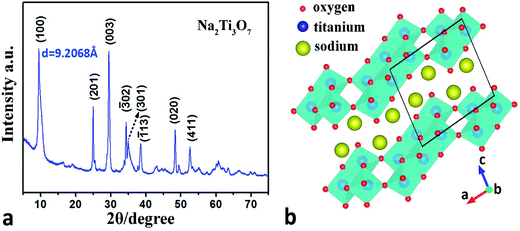 | ||
| Fig. 1 (a) XRD spectrum of the synthesized Na2Ti3O7 NW. (b) The crystal structure of sodium titanate; the black framed area shows the unit cell of the structure. | ||
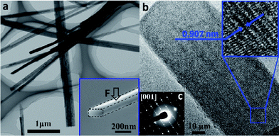
The different dimensions of the synthesized Na2Ti3O7 NW can be seen from a typical low-magnification TEM image (Fig. 2a). The width of the NW ranges from 20–700 nm and the longest NW observed is around 40 μm. According to the SEM imaging and AFM topography measurement, the cross-sections of these NWs have a rectangular shape with the height-to-width ratio between 0.73–0.86. Na2Ti3O7 NWs with various wire dimensions are pictured in the transmission electron microscopy (TEM) image and a typical cross-section area is shown in the SEM image as an inset. It should be noted that in all experiments the loading force is applied along the width direction as indicated by the arrow in the inset of Fig. 2a. An HRTEM image of a well crystallized Na2Ti3O7 NW is taken along its [001] direction (along the nanowire) as shown in Fig. 2b. The corresponding electron diffraction pattern (Fig. 2c) indicates that the sample has a highly crystalline structure, which is in good agreement with XRD diffraction pattern. The electron diffraction pattern can be attributed to monoclinic Na2Ti3O7 structure (C2/m space group, a = 0.808 nm, b = 0.378 nm, c = 0.916 nm, β = 94.0°).46
3.2. Bending behaviours
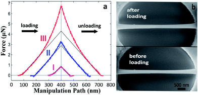
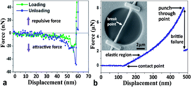
Loading-unloading cycles were performed to investigate the bending behaviours of a single Na2Ti3O7 NW. Prior to the bending test, a circular hole (500–700 nm deep) was drilled using focus ion beam (FIB) on ITO substrate where Na2Ti3O7 NWs are also sparsely dispersed (Fig. S1a in ESI†). Then, a selected Na2Ti3O7 NW is picked up using a nanomanipulator tip (Fig. S1b†) and placed across the hole. The sample preparation is completed by welding the two ends of the bridged Na2Ti3O7 NW using electron beam induced Pt deposition (Fig. S1c†). Under AFM contact mode scanning, the topography of a bridged Na2Ti3O7 NW is obtained before it is subjected to a force exerted at the center of the sample (Fig. S1d†). As shown in Fig. 3a, the force vs. displacement (F–d) curves are generally symmetric during loading and unloading processes for all three loading-unloading cycles. Such a symmetric characteristic indicates the full recovery from the deformation, signifying an elastic deformation process. Specifically, it shows that the F–d curve exhibits a linear behavior when the displacement is relatively small (curve I). When the displacement exceeds around one third of the NW height, a nonlinear deformation is observed (curve II), and the nonlinearity becomes more significant with the continuing displacement (curve III). Similar bending behavior is also observed on Na2Ti3O7 NWs with different dimensions (Fig. S2†). According to the SEM images in Fig. 3b, the Na2Ti3O7 NW shows no residual deformation or indent mark after unloading, which indicates that the Na2Ti3O7 NW exhibits excellent elasticity and nonlinear elastic deformation behavior.During the loading and unloading processes, an adhesive phenomenon47 typical on AFM measurements is observed. Fig. 4a shows the AFM detection of the adhesive phenomenon where an attractive force (negative force) of ∼30 nN and ∼50 nN are detected during loading and unloading processes, respectively. Such attractive force originates from van der Waals force between the AFM tip and NW surface.48 Interestingly, we found that the attractive force during unloading is generally 15–50% larger than that during loading. This can be understood while considering that the contact surface is larger during unloading, attributed mainly from the indentation induced concave NW surface (see Fig. S3†). Alternatively more surface atoms are involved in the interaction between the AFM tip and the NW surface during unloading and therefore generate stronger attractive force.
3.3. Modified beam theories
As shown in Fig. 4b, when the AFM tip approaches and starts contacting the sample surface, the force on the tip becomes repulsive and increases linearly at first for about 100 nm sample deflection. As the sample displacement increases, the measured force increases continually and nonlinearly, which eventually shift to a sudden drop from ∼8 μN to ∼2 μN at a displacement of 341 nm (Fig. 4b). The overall profile of the F–d curve is quite similar to that observed during in situ bending of Si NW.49 Considering the symmetric F–d curves during loading-unloading cycles (Fig. 3a) and the sudden force drop, it can be concluded that Na2Ti3O7 NW behaves like a typical brittle material. After failure, the Na2Ti3O7 NW is fractured at the center of the bridged beam where the force is applied as shown in the SEM image of Fig. 4b inset. Extensive bending tests were carried out and the same results are shown that the Na2Ti3O7 NW is exhibiting a nonlinear elastic deformation and brittle behavior.The nonlinear elastic behavior of the NW can be described by the Euler–Bernoulli beam theory (EBT) model modified with the axial extension, the impact from which is normally unnoticeable at macro-scale on the bending deformation while it is profound for NWs. The governing equation is given as below:
 | (1) |
 | (2) |
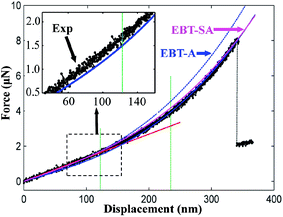
There are several possible reasons for this discrepancy, such as approximations made while deriving the solution from the governing equation, and measurement errors for the geometrical parameters of the NW, the force and the displacement. Another possible reason is that the model ignores the so-called surface effect, which is originated from the surface atoms who behave differently from their bulk counterparts (as they possess less neighbour atoms). In this regard, the NW is approximated as a “core–shell” structure, where the thin “shell” layer represents the surface atoms and possesses different mechanical properties from the “core” region. The detailed derivation of the modified beam model incorporated with surface effect (denoted as EBT-SA) can be found from the work reported by Zhan and Gu50 and is summarised in ESI.† As shown in Fig. 5, although the impact from the surface effect is supposed to become significant while the cross-sectional size is much smaller than around 100 nm, the EBT-SA model is found to give an excellent prediction for the mechanical behaviour of the studied Na2Ti3O7 NWs, whose wire width are around 400 nm. It can be concluded that the nonlinear elastic deformation of the Na2Ti3O7 NW can be well explained by the beam model modified with axial extension effect, and the additional incorporation of the surface effect could further improve the theoretical prediction.
3.4. Mechanical properties
We then look into the mechanical properties of the Na2Ti3O7 NW. To avoid the accumulating errors while using the modified beam models which contain several fitting parameters, the linear region (i.e., small displacement) as indicated by the red line in Fig. 5, is adopted to interpret the mechanical properties of the NW. According to the beam theory, the influence from the axial extension can be ignored in this region, and the F and d for a doubly clamped beam follow a linear relation given by the classical Euler–Bernoulli beam model as:
 | (3) |
Fig. 6 shows the estimated Young's moduli of Na2Ti3O7 NWs with different lengths. To accurately determine the Young's modulus, NWs with similar diameters are repeated 5 to 10 times. No obvious trend is observed with the Young's modulus against the change of the Na2Ti3O7 NW's length for wire width around 400 nm. The diversity in the Young's modulus might be slightly attributed to the defects/surface contamination of the single Na2Ti3O7 NW. The variations of sizes between individual NWs can also lead to this diversity. More importantly, the Na2Ti3O7 is monoclinic crystal, which possesses 13 independent elastic constants according to the generalized Hooke's law. In our experiments, although the crystal direction can be controlled along the length direction, the other two orthogonal lateral directions are uncertain which would lead to the variation of Young's modulus. The effective Young's modulus of the Na2Ti3O7 NW ranges from 21.4 GPa to 45.5 GPa and the average value is estimated as 32.5 ± 7.4 GPa. It should be noted that there is currently no source on the Young's modulus of bulk sodium titanate materials.
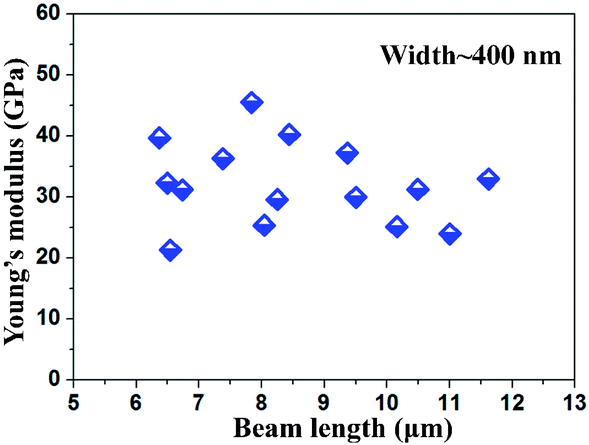 | ||
| Fig. 6 Experimental results of effective Young's modulus of Na2Ti3O7 NWs with different beam length. | ||
Lastly, it is also of great interest to discuss the yielding strength of the Na2Ti3O7 NW during bending. According to the classical mechanics, the top and bottom surfaces of the NW suffer the biggest stress. For a doubly clamped beam with a central loading, the maximum stress can be calculated according to the equation below50
 | (4) |
By using the maximum force in F–d curve before the onset of fracture, the yielding strength of various Na2Ti3O7 NWs (length to width ratio around 20) are shown in Table 1 with the average yield strength as 2.7 ± 0.7 GPa. To compare with other NWs, the measured effective Young's modulus of Na2Ti3O7 NW is in the same range with that reported for CdS (11–90 GPa)51 and ZnS (35.9 ± 3.5 GPa)52 for wire width between 200–400 nm. What is more, the measured yield strength of Na2Ti3O7 NW has the same order with that of ZnO and GaN which are the most extensively characterized nanowires.22
| Sample | Width (nm) | Height (nm) | Length (nm) | Fmax (nN) | σmax (GPa) |
|---|---|---|---|---|---|
| 1 | 274 | 256 | 4680 | 16![[thin space (1/6-em)]](https://www.rsc.org/images/entities/char_2009.gif) 606 606 |
3.24 |
| 2 | 311 | 227 | 5030 | 14![[thin space (1/6-em)]](https://www.rsc.org/images/entities/char_2009.gif) 730 730 |
3.46 |
| 3 | 442 | 322 | 8250 | 15![[thin space (1/6-em)]](https://www.rsc.org/images/entities/char_2009.gif) 384 384 |
2.07 |
| 4 | 472 | 344 | 9520 | 15![[thin space (1/6-em)]](https://www.rsc.org/images/entities/char_2009.gif) 703 703 |
2.00 |
| 5 | 488 | 356 | 10![[thin space (1/6-em)]](https://www.rsc.org/images/entities/char_2009.gif) 160 160 |
22![[thin space (1/6-em)]](https://www.rsc.org/images/entities/char_2009.gif) 242 242 |
2.74 |
4. Conclusion
In summary, we report the first study on the mechanical properties of Na2Ti3O7 NWs through doubly-clamped bending experiments. It is found that the Na2Ti3O7 NW exhibits a brittle behavior, and nonlinear elastic deformation is observed when the bending displacement is larger than half of the NW's height. With increasing displacement, the nonlinearity increases. Theoretical analysis reveals that the nonlinear elastic bending behavior of the Na2Ti3O7 NW is attributed from the bending induced axial extension. The Young's modulus for the Na2Ti3O7 NW is found to vary from 21.4 GPa to 45.5 GPa, with an average value of 32.5 ± 7.4 GPa. Yielding strength of the Na2Ti3O7 NW is around 2.7 ± 0.7 GPa. The excellent mechanical properties presented by Na2Ti3O7 NW suggest that they can be exceptionally useful as building blocks in the development of future nano-scale devices.Acknowledgements
Supports from the ARC Discovery Project (DP130102120) and Central Analytical Research Facility (CARF) of Queensland University of Technology (QUT) are gratefully acknowledged.References
- D. Hennings, M. Klee and R. Waser, Adv. Mater., 1991, 3, 334–340 CrossRef CAS.
- R. E. Newnham, MRS Bull., 1997, 22, 20–34 CrossRef CAS.
- O. Rusina, O. Linnik, A. Eremenko and H. Kisch, Chem.–Eur. J., 2003, 9, 561–565 CrossRef CAS PubMed.
- J. J. Urban, W. S. Yun, Q. Gu and H. Park, J. Am. Chem. Soc., 2002, 124, 1186–1187 CrossRef CAS PubMed.
- D. Yu, J. Wu, L. Zhou, D. Xie and S. Wu, Compos. Sci. Technol., 2000, 60, 499–508 CrossRef CAS.
- T. Imai, Y. Nishida, M. Yamada, I. Shirayanagi and H. Matsubara, J. Mater. Sci. Lett., 1987, 6, 1257–1258 CrossRef CAS.
- H. Pan, X. Lu, X. Yu, Y. S. Hu, H. Li, X. Q. Yang and L. Chen, Adv. Energy Mater., 2013, 3, 1186–1194 CrossRef CAS.
- M. Shirpour, J. Cabana and M. Doeff, Energy Environ. Sci., 2013, 6, 2538–2547 CAS.
- D. Yang, Z. Zheng, Y. Yuan, H. Liu, E. R. Waclawik, X. Ke, M. Xie and H. Zhu, Phys. Chem. Chem. Phys., 2010, 12, 1271–1277 RSC.
- R. A. Aziz, I. I. Misnon, K. F. Chong, M. M. Yusoff and R. Jose, Electrochim. Acta, 2013, 113, 141–148 CrossRef PubMed.
- P. Hernández-Hipólito, M. García-Castillejos, E. Martínez-Klimova, N. Juárez-Flores, A. Gómez-Cortés and T. E. Klimova, Catal. Today, 2014, 220–222, 4–11 CrossRef PubMed.
- J. Q. Huang, Z. Huang, W. Guo, M. L. Wang, Y. G. Cao and M. C. Hong, Cryst. Growth Des., 2008, 8, 2444–2446 CAS.
- D. Yang, S. Sarina, H. Zhu, H. Liu, Z. Zheng, M. Xie, S. V. Smith and S. Komarneni, Angew. Chem., Int. Ed., 2011, 50, 10594–10598 CrossRef CAS PubMed.
- H. Y. Zhu, Y. Lan, X. P. Gao, S. P. Ringer, Z. F. Zheng, D. Y. Song and J. C. Zhao, J. Am. Chem. Soc., 2005, 127, 6730–6736 CrossRef CAS PubMed.
- H. Liu, Z. Zheng, D. Yang, X. Ke, E. Jaatinen, J. C. Zhao and H. Y. Zhu, ACS Nano, 2010, 4, 6219–6227 CrossRef CAS PubMed.
- H. Zhang, X. P. Gao, G. R. Li, T. Y. Yan and H. Y. Zhu, Electrochim. Acta, 2008, 53, 7061–7068 CrossRef CAS PubMed.
- D. J. Yang, Z. F. Zheng, H. Y. Zhu, H. W. Liu and X. P. Gao, Adv. Mater., 2008, 20, 2777–2781 CrossRef CAS PubMed.
- F. Takahashi, Z. Sun, K. Fukushi, Y. Oshima and K. Yamamoto, J. Supercrit. Fluids, 2012, 61, 126–133 CAS.
- D. Hu, X. Kong, K. Mori, Y. Tanaka, K. Shinagawa and Q. Feng, Inorg. Chem., 2013, 52, 10542–10551 CrossRef CAS PubMed.
- T. Kennedy, E. Mullane, H. Geaney, M. Osiak, C. O'Dwyer and K. M. Ryan, Nano Lett., 2014, 14, 716–723 CrossRef CAS PubMed.
- S. Gong, W. Schwalb, Y. Wang, Y. Chen, Y. Tang, J. Si, B. Shirinzadeh and W. A. Cheng, Nat. Commun., 2014, 5, 1–8 CrossRef.
- H. D. Espinosa, R. A. Bernal and M. A. Minary-Jolandan, Adv. Mater., 2012, 24, 4656–4675 CrossRef CAS PubMed.
- V. Pachauri, C. Subramaniam and T. Pradeep, Chem. Phys. Lett., 2006, 423, 240–246 CrossRef CAS PubMed.
- F. Cao, W. Hu, L. Zhou, W. Shi, S. Song, Y. Lei, S. Wang and H. Zhang, Dalton Trans., 2009, 42, 9246–9252 RSC.
- T. Takahashi, K. Takei, E. Adabi, Z. Fan, A. M. Niknejad and A. Javey, ACS Nano, 2010, 4, 5855–5860 CrossRef CAS PubMed.
- B. Wu, A. Heidelberg, J. J. Boland, J. E. Sader, X. M. Sun and Y. D. Li, Nano Lett., 2006, 6, 468–472 CrossRef CAS PubMed.
- B. Wu, A. Heidelberg and J. J. Boland, Nat. Mater., 2005, 4, 525–529 CrossRef CAS PubMed.
- B. Wen, J. E. Sader and J. J. Boland, Phys. Rev. Lett., 2008, 101, 1755021–1755024 CrossRef.
- H. Zhang, J. Tang, L. Zhang, B. An and L. C. Qin, Appl. Phys. Lett., 2008, 92, 1731211–1731213 Search PubMed.
- X. Li, H. Gao, C. J. Murphy and K. K. Caswell, Nano Lett., 2003, 3, 1495–1498 CrossRef CAS.
- S. Cuenot, S. Demoustier-Champagne and B. Nysten, Phys. Rev. Lett., 2000, 85, 1690–1693 CrossRef CAS.
- J. P. Salvetat, G. A. D. Briggs, J. M. Bonard, R. R. Bacsa, A. J. Kulik, T. Stöckli, N. A. Burnham and L. Forró, Phys. Rev. Lett., 1999, 82, 944–947 CrossRef CAS.
- A. Kis, S. Kasas, B. Babić, A. J. Kulik, W. Benoit, G. A. D. Briggs, C. Schönenberger, S. Catsicas and L. Forro, Phys. Rev. Lett., 2002, 89, 2481011–2481014 CrossRef.
- G. Y. Jing, H. L. Duan, X. M. Sun, Z. S. Zhang, J. Xu, Y. D. Li, J. X. Wang and D. P. Yu, Phys. Rev. B: Condens. Matter Mater. Phys., 2006, 73, 2354091–2354096 CrossRef.
- Y. Chen, B. L. Dorgan, D. N. McIlroy and A. D. Eric, J. Appl. Phys., 2006, 100, 1043011–1043017 Search PubMed.
- Y. Chen, I. Stevenson, R. Pouy, L. Wang, D. N. McIlroy, T. Pounds, M. G. Norton and D. E. Aston, Nanotechnology, 2007, 18, 1357081–1357088 Search PubMed.
- D. A. Walters, L. M. Ericson, M. J. Casavant, J. Liu, D. T. Colbert, K. A. Smith and R. E. Smalley, Appl. Phys. Lett., 1999, 74, 3803–3805 CrossRef CAS PubMed.
- I. W. Frank, D. M. Tanenbaum, A. M. Van der Zande and P. L. McEuen, J. Vac. Sci. Technol., B: Nanotechnol. Microelectron.: Mater., Process., Meas., Phenom., 2007, 25, 2558–2561 CrossRef CAS.
- B. Lee and R. E. Rudd, Phys. Rev. B: Condens. Matter Mater. Phys., 2007, 75, 1953281–1953315 Search PubMed.
- H. Zhan and Y. Gu, Comput. Mater. Sci., 2012, 55, 73–80 CrossRef CAS PubMed.
- H. Zhan and Y. Gu, J. Phys. D: Appl. Phys., 2012, 45, 4653041–4653110 CrossRef.
- H. F. Zhan, Y. T. Gu, C. Yan, X. Q. Feng and P. K. D. V. Yarlagadda, Comput. Mater. Sci., 2011, 50, 3425–3430 CrossRef CAS PubMed.
- S. Andersson and A. Wadsley, Acta Crystallogr., 1962, 15, 194–201 CrossRef CAS.
- Q. Chen, G. H. Du, S. Zhang and L. M. Peng, Acta Crystallogr., Sect. B: Struct. Sci., 2002, 58, 587–593 CrossRef CAS PubMed.
- S. Andersson and A. Wadsley, Acta Crystallogr., 1961, 14, 1245–1249 CrossRef CAS.
- O. Yakubovich and V. Kireev, Crystallogr. Rep., 2003, 48, 24–28 CrossRef CAS.
- B. Cappella and G. Dietler, Surf. Sci. Rep., 1999, 34, 1–104 CrossRef CAS.
- H. J. Butt, B. Cappella and M. Kappl, Surf. Sci. Rep., 2005, 59, 1–152 CrossRef CAS PubMed.
- A. Heidelberg, L. T. Ngo, B. Wu, M. A. Phillips, S. Sharma, T. I. Kamins, J. E. Sader and J. J. Boland, Nano Lett., 2006, 6, 1101–1106 CrossRef CAS PubMed.
- H. Zhan and Y. Gu, J. Appl. Phys., 2012, 111, 0843051–0843059 Search PubMed.
- P. Gao, K. Liu, L. Liu, Z. Wang, Z. Liao, Z. Xu, W. Wang, X. Bai, E. Wang and Y. Li, J. Electron Microsc., 2010, 59, 285–289 CrossRef CAS PubMed.
- X. Li, X. Wang, Q. Xiong and P. C. Eklund, Nano Lett., 2005, 5, 1982–1986 CrossRef CAS PubMed.
- J. E. Sader, J. W. Chon and P. Mulvaney, Rev. Sci. Instrum., 1999, 70, 3967–3969 CrossRef CAS PubMed.
Footnote |
| † Electronic supplementary information (ESI) available: ESI is available for the experimental set-up and related theoretical backgrounds. See DOI: 10.1039/c4ra11753k |
| This journal is © The Royal Society of Chemistry 2014 |

