DOI:
10.1039/C4RA11042K
(Paper)
RSC Adv., 2014,
4, 58596-58607
Preparation of hierarchically structured Y zeolite with low Si/Al ratio and its applications in acetalization reactions†
Received
23rd September 2014
, Accepted 29th October 2014
First published on 30th October 2014
Abstract
Hierarchically structured Y zeolites were prepared by a post-synthetic strategy, where the as-made NaY zeolite was sequentially treated by a lactic acid solution and an alkaline solution containing cetyltrimethyl ammonium bromide (CTAB). Many techniques, including X-ray diffraction (XRD), Scanning Electron Microscopy (SEM), N2 adsorption–desorption, Fourier-transform infrared spectroscopy (FT-IR), Thermogravimetric analysis (TG-DTG) and NH3 Temperature Programmed Desorption (NH3-TPD), were applied to characterize the chemical and textural properties of the samples. The results show that lactic acid pre-modification of NaY zeolite may cause on the one hand Na+ cation removal by proton exchange and on the other hand the dealumination of the zeolite framework with the formation of amorphous silicon-rich species offering nutrients for the fabrication of mesoporosity. After alkaline treatment in the presence of surfactant CTAB, mesoporosity can be successfully introduced into the NaHY zeolites with the microporous structures well preserved. Furthermore, the hierarchically structured Y zeolites exhibit much better performances in the acetalization reactions with large sized molecules involved. This could be attributed to the enhanced diffusion ability of large sized guest molecules through the combination of mesoporosity and microstructures compared with pure microporous Y zeolites.
1. Introduction
Zeolites are crystalline microporous aluminosilicate materials with even and tunable pore structures and have already found applications in adsorption, separation, purification and catalysis areas.1–5 Amongst others, zeolite Y with FAU topological structures are most important and frequently utilized as the active phase in both fluid catalytic cracking (FCC) and hydrocracking catalysts due to the high acidity, large internal surfaces and uniform channels (0.8 nm) and cavities (α cage, 1.3 nm).6–8 Besides, zeolite Y also finds applications in many other industrial processes, such as aldol condensations9 and Knoevenagel condensation processes10 of benzaldehyde with n-butyl alcohol and malononitrile respectively, hydrogenation of aromatic,11 hydrodesulfurization of 4,6-Dimethyldibenzothiophene12 as catalysts or catalyst supports because of its excellent chemical and textural properties. However, the intrinsic microporous nature of zeolite Y (<2.0 nm) always impose diffusional limitations on large-sized organic molecules, which may hinder the reactants/products to approach or leave the active sites in the zeolite structures and may result in lowering the conversion or further reaction with coke deposition and catalyst deactivation.
In order to circumvent the diffusional limitations of large-sized molecules, several potential procedures have been explored, including preparations of ordered mesoporous materials, i.e. MCM-41 and SBA-15 etc., synthesis of extra-large pore molecular sieves, and fabrication of nanosized zeolites, mesostructured zeolites or zeolites with hierarchical porosity and so on. The topics are also comprehensively reviewed recently by different groups.13–20 Nevertheless, the inferior hydrothermal stability and relative weak acidity of the mesoporous materials, the limited pore widening of the extra-large pore molecular sieves all constrain these materials' utilities in large scale.15 Therefore, the creation of microporous zeolites with intra-and/or inter-mesopores is a much more promising way for improving the large-sized molecule transportation abilities while reserving their zeolitic properties. Until now, many approaches, classified as “bottom-up” and “top-down”, have been described in the literature for the preparation of hierarchically structured Y zeolites, among which most “bottom-up” approaches involve the addition of mesoscale templates, either hard or soft templates.21 For example, Zhu and co-workers once reported a strategy for the preparation of hierarchical mesoporous Y zeolite by assembling zeolite Y or sodalite fragments around mesoscale cationic surfactant cetyltrimethylammonium bromide (CTAB) micelles with cosolvent tertbutyl alcohol (TBA) and the 1,3,5-trimethylbenzene (TMB) additive and the obtained sample exhibited superior adsorption capacity towards bulky molecule N-nitrosonornicotine owing to its hierarchical mesostructure comparing to conventional NaY zeolite.22 However, the mesostructured Y zeolite owned very low micropore volume because of its relatively poor crystallinity. Inayat et al. firstly reported the synthesis of assemblies of mesoporous FAU-type zeolite nanosheets with a low Si/Al molar ratio of 1.0–1.5 using 3-(trimethoxysilyl)propyl hexadecyl dimethyl ammonium chloride (TPHAC) as template.23 However, the low Si/Al molar ratio largely limited the material's utility. More recently, Fu et al. reported that mesoporous zeolite Y was successfully synthesized from a synthetic mixture containing water glass and silylated quaternary ammonium (N,N-dimethyl-N-octadecyl-N-(3-triethoxysilylpropyl) ammonium [(C2H5O)3SiC3H6N(CH3)2C18H37]+ cation) that was used as a mesoscale template. And the obtained mesoporous Y zeolite was used as a support for loading Pd and displayed much higher activity in hydrodesulfurization (HDS) of 4,6-dimethyldibenzothiophene (4,6-DM-DBT, 97.3%) than the Pd catalysts supported on mesoporous ZSM-5, mesoporous Beta zeolite, conventional microporous Y zeolite and alumina.12 Furthermore, Liu et al. reported the hydrothermal synthesis of hierarchical zeolite Y, actually a mixture of Y and P zeolite, using an organosilane surfactant of [3-(trimethoxysilyl)propyl]octadecyldimethylammonium chloride [(CH3O)3SiC3H6N(CH3)2C18H37]Cl (TPOAC), which could be homogeneously dispersed in viscous gel for synthesizing zeolite Y, as mesopore-generating agent and the prepared mesostructrued Y zeolite owned a sharp mesopore size distribution centered at 3.8 nm.9 The mesostructured zeolite showed much higher activity and better resistance to deactivation as compared with conventional zeolite Y when used as catalysts in the aldol condensation of benzaldehyde with n-butyl alcohol, attributing to the improved mass transportation ability of guest species through the interconnected micropore-to-mesopore networks in the mesostructured Y zeolite sample. Besides, Jin et al. also presented an approach for the synthesis of mesoporous, pure zeolite Y by using the same organosilane surfactant as template, and the ratio of mesoporosity vs. microporosity can be adjusted by varying the addition amount of the template. The obtained mesostructured Y zeolite was used as catalyst additive (5%) combining with conventional USY zeolite (25%) for fabrication of cracking catalyst and the catalyst was evaluated in heavy oil catalytic cracking process. Comparing with the classical Y derived catalyst, the mesostructured Y zeolite contained catalyst displayed superior catalytic performance with a significant increase of gasoline yields and reduction of coke and dry gas yields.24 Although many examples have been recorded for the preparation of mesostructured Y zeolites in the presence of organic template through “bottom-up” approach, it is still not convenient to obtain hierarchically structured zeolite Y because of the difficulty of dispersing the organic templates into the parent gel used for the preparation of zeolite Y, and only those organic surfactants with specially designed structures, such as organosilane species, can be successfully utilized. Another way for the formation of hierarchically structured zeolite Y categorized in “bottom-up” approach is the synthesis of nano-sized Y zeolite particles and thereafter fabrication of inter-mesopores by self-assembly of the nanoparticles.20,25 So far, many attempts have been devoted to synthesize zeolite Y nanoparticles, either in the presence of structure directing agent of tetramethyl ammonium cations (TMA+),26–30 by space-confined synthesis using starch as a template31 or by tuning the crystallization parameters.32 However, the decreased particle size of zeolite Y may cause some problems during usage, such as a descending of the micropore volume, recovery difficulties and poorer stabilities etc.15 Therefore, more and more attentions are drawn towards the preparation of hierarchically structured FAU zeolites in “Top-Down” approaches, including steaming treatment or steaming combining with acid leaching, alkaline leaching, desilication combining with re-crystallization in the presence of a mesopore-directing agent and surfactant-templated structure arrangement.21 Lutz and co-workers thoroughly studied the structural and textural changes of zeolite Y during steam treatment process and pointed out that different kinds of mesopores formed along with dealumination and silicon species migration,33–35 where intracrystalline (closed) mesopores occur in the nuclei while open pores at the crystal surface due to decomposition of its corresponding frameworks, furthermore, a third type of mesopores formed by dehydroxylation of the hydroxyl nests left by dealumination.33–35 Jassen et al. also investigated the pore structures of steamed zeolite Y and imaged the mesopores through three-dimensional transmission electron microscopy (3D-TEM) so as to gain insight into the shape and three dimensional ordering of the pore structures.36,37 They stated that besides some (small amount of) cylindrical pores connecting the external surface with the interior of the crystallite, most of the mesopores formed during steam process are present as cavities which are blocked inner the zeolite particles and only connected with the outer surface through micropore channels. Therefore, to what extent the accessibility and diffusion can be enhanced by these cavities was questioned. After a special hydrothermal treatment the cavities adjacent to one another in the zeolite may coalesce with the formation of interconnected cylindrical mesopores, which can apparently enhance the diffusion properties of zeolites. Based on this, de Jong and co-workers tried base leaching of the steamed Y zeolites in dilute NaOH solution at room temperature for a quite short duration of 15 min and they found that besides zeolitic micropores and large mesopores (ca. 30 nm) caused by steaming and acid leaching, another smaller sponge-like mesopores (ca. 3 nm) were formed by desilication during this alkaline leaching.38,39 The tri-modal porosity was beneficial for diffusion of the cracking products, which suppressed further cracking, increased diesel selectivity and decreased coke formation in VGO cracking. However, the framework structures of the zeolites were strongly destructed during direct alkaline leaching along with a substantial loss of microporosity. In this context, Verboekend et al. proposed a procedure in which an organic pore-directing agent, TPA+ for instance, was added in alkaline solution so as not only to tailor the mesopore structures but also to prevent realumination and amorphization of the zeolite crystals.40,41 After this desilication treatment with the assistance of organic pore-directing agent, mesoporosity was introduced and the crystallinity and micropore volume were better retained. Besides, Garcia-Martinez and co-workers also developed a facile procedure for the preparation of mesostructured Y zeolite in a surfactant-templated structure re-arrangement process.21,42–45 Mesostructured Y zeolites with secondary intracrystalline mesoporosity can be obtained in a single-step process combing alkaline treatment with surfactant templating while the intrinsic zeolitic microporosity was well preserved. The resultant zeolite exhibited the improved catalytic behavior in the cracking of vacuum gasoil due to enhanced diffusion ability. Similar to Garcia-Martinez' report, Chal et al. prepared mesostructrued Y zeolites in TMAOH solution in the presence of CTAB. Two interconnected pore systems, micro- and mesopores, in the zeolite crystals can be fabricated through pseudomorphic transformation of parent Y zeolite. However, the modification objects aforementioned are all zeolites with high silica to alumina molar ratios in the framework structures and examples of introduction of mesopores into Y zeolites with low Si/Al molar ratios are very rare,41,43,46,47 mostly since the abundant aluminum ions in the zeolite framework may hinder the dissolution of the silicon species by the alkaline and thus the formation of mesopores48,49 or since Si–O–Al bonds in high aluminum zeolites are not as labile as the Si–O–Si under basic conditions and cannot rearrange the structure so as to incorporate mesoporosity.
Herein, hierarchically structured Y zeolites were prepared in top-down procedure assisted by surfactant CTAB in an alkaline solution using lactic acid pretreated NaY zeolite as starting material. Before alkaline treatment, NaY zeolite was pre-modified by lactic acid in order to transform the zeolite framework to some extent to amorphous silicon-rich species. In the following, mesoporosity can be introduced with the assistance of surfactant CTAB, where the formed amorphous silicon-rich species play an essential role. Besides, the dissolution degree of the Si-rich non-framework species in different alkaline solutions greatly affected the mesoporosity formation process. The hierarchically structured Y zeolites with mesopores are expected to be of enhanced diffusion abilities for large molecules in the catalytic reactions when used as catalysts, and thus their performances in acetalization reaction of cyclohexanone were investigated.
2. Experimental section
2.1 Reagents
All chemical reagents were of analytical grade and used as received without further purification. Lactic acid (HLA), NaOH, NH3·H2O (25 wt%), cetyltrimethyl ammonium bromide (CTAB) were provided by Sinopharm Chemical Reagent Co., Ltd. Si, Al and Na ions standard solutions were provided by Alfa-Asea. NaY and HY zeolites were supplied by Huahua Catalyst Manufacturing Company, China. Deionized water was used directly without further purification.
2.2 Material preparations
Hierarchically structured Y zeolites were prepared as following: 1.0 g of NaY zeolite was added into 20.0 mL 0.625 mmol L−1 lactic acid aqueous solution with stirring at room temperature for 1 h, and then the resultant slurry was transferred into a Teflon vessel, sealed and heated at 100 °C for 2 h. After treatment, the mixture was filtrated and washed with hot water and then dried, the obtained sample was denoted as HLA-HT. 0.2 g NaOH or 3.4 g NH3·H2O (25 wt%) was added into 30 mL of water containing 0.72 g of cetyltrimethyl ammonium bromide (CTAB) with stirring. 1.00 g sample HLA-HT was added into the clear solution with keeping stirring for another 1 h. The mixture was transferred into a Teflon-lined vessel, sealed and heated at 150 °C under autogenous pressure for 1 day, after which the mixture was filtrated, washed with hot water and then dried. The obtained samples were denoted as NaOH-CTAB-a and NH3-CTAB-a, respectively. NaOH-CTAB-a and NH3-CTAB-a were calcined at 550 °C for 5 h to remove the occluded CTAB organic moieties, and the resultant samples were denoted as NaOH-CTAB-c and NH3-CTAB-c, respectively. Samples NaOH-CTAB-c and NH3-CTAB-c were ion-exchanged with 1.0 M NH4Cl solution at 80 °C for three times and then converted to H+ form by calcination at 550 °C for 5 h. The prepared samples were denoted as NaOH-CTAB-cat and NH3-CTAB-cat, respectively.
2.3 Characterization
X-ray diffraction patterns (XRD) of zeolite Y were collected by Rigaku-Ultima diffractometer using a Cu Kα radiation source (λ = 0.15432 nm). The relative crystallinity was calculated by comparing the eight peak intensities of the treated samples with that of the parent NaY sample according to SH/T 0340-92.50,51 The framework Si/Al ratios of Y zeolites were determined from the Y zeolite unit cell a0 detected according to literature.1 In order to determine the bulk Si/Al molar ratios of the samples, Inductively Coupled Plasma Atomic Emission Spectrometry (ICP-AES) were recorded on a Thermo IRIS Intrepid II XSP atomic emission spectrometer after dissolving the calcined samples in HF solution. Scanning electron microscope (SEM) was performed on a Hitachi S-4800 field emission scanning electronmicroscope (FE-SEM, Hitachi, Japan) with an acceleration voltage of 3 kV. Fourier transform infrared spectra (FTIR) were performed on a Nicolet Fourier transform infrared spectrometer (NEXUS 670) combined with the conventional KBr wafer technique. The spectra were collected for the wavenumber range of 400–4000 cm−1, with a resolution of 4 cm−1. Thermo gravimetric analysis (TG) was performed using a NET2SCH STA449F3 TGA analyzer with heating rate of 10 °C min−1 from 25 to 800 °C under an air flow. N2 adsorption–desorption isotherms were measured at −196 °C on a Quantachrome Autosorb-3B volumetric adsorption analyzer. Before the measurements, the samples were out gassed for 6 h in the degas port of the adsorption apparatus at 300 °C. The BET specific surface area was calculated using adsorption data acquired at a relative pressure (P/P0) range of 0.05–0.30 and the total pore volume determined from the amount adsorbed at a relative pressure of about 0.99. The pore size distribution (PSD) curves were calculated from the analysis of adsorption branch of the isotherm using the Barrett–Joyner–Halenda (BJH) algorithm. Transmission electron microscopy (TEM) experiments were conducted on TECNAI G2 F30 operating at 300 kV. For the TEM image, the specimens were dispersed in ethanol and placed on holey copper grids. 29Si and 27Al MAS NMR spectra were measured on a VARIAN VNMRS 400WB NMR spectrometer under one-pulse conditions. The spectra were obtained with a frequency of 79.43 MHz, a spinning rate of 3.0 kHz, and a recycling delay of 60 s. The chemical shift was referred to as Q8M8 ([(CH3)3SiO]8SiO12). The 27Al NMR spectra were recorded with a frequency of 104.18 MHz, a spinning rate of 10.0 kHz, and a recycling delay of 4 s. KAl(SO4)2·12H2O was used as the reference for chemical shift. Temperature-programmed desorption of NH3 (NH3-TPD) testing was applied to detect the acidity properties of the samples and the tests were performed using a TP-5080 chemisorption instrument (Xianquan Co., Ltd, Tianjin, China) with a thermal conductivity detector (TCD). After pretreatment at 550 °C under flowing helium (25 mL min−1) for 1 h, each sample (100 mg) was cooled to 100 °C, and then adsorbed to saturation by ammonia for 30 minutes. Ammonia physically adsorbed on the catalyst was removed by flushing the sample with helium (25 mL min−1) for 1 h at the adsorption temperature. Thermal desorption of ammonia was carried out in the temperature range of 100–550 °C increasing at a rate of 10 °C min−1.
2.4 Catalytic evaluation
Acetalization of cyclohexanone with glycol and pentaerythritol were used as model reactions and carried out under slurry phase reaction conditions using a conventional oil bath attached to a condenser according to literature.52 A typical reaction mixture, in a 10 mL round bottle flask, contained cyclohexanone (20 mmol), glycol (32 mmol, excess amount) (if pentaerythritol was used, addition amount was 10 mmol), n-decane (10 mmol) and a freshly activated catalyst (50 mg). Activation of the catalyst was achieved by calcination at 550 °C for 5 h. The reaction was carried out at 120 °C for 2 h. After cooling to room temperature, the flask was washed several times with acetone. All the mixture was collected and separated by centrifugation. The liquid supernatant was analyzed using a Shimadzu GC-2014 gas chromatograph with an Rtx1-Wax capillary column and FID detector. The conversion was calculated based on cyclohexanone using the internal standard method, where n-decane was applied as the internal standard. The formation of diacetals of pentaerythritol was confirmed by GCMS. The acetalization reactions are illustrated in Scheme 1.
 |
| | Scheme 1 Acetalization of Cyclohexanone with glycol (I) and pentaerythritol (II). | |
3. Results and discussion
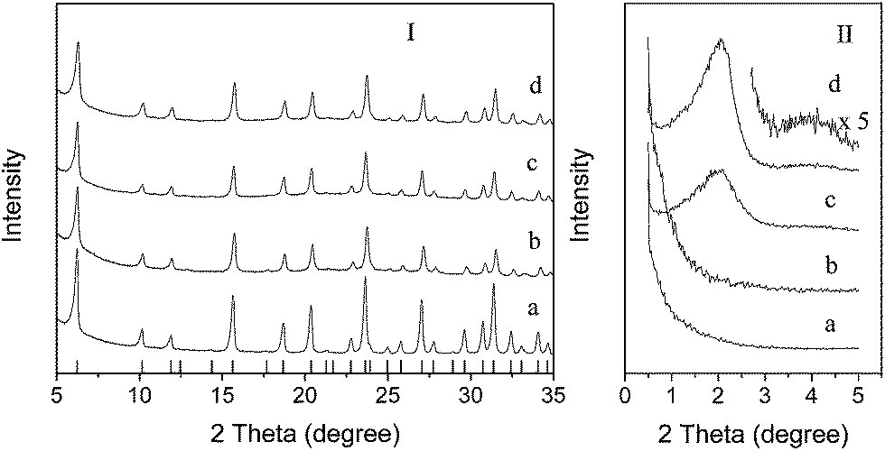
Fig. 1 exhibits the wide- and small-angle XRD patterns of parent NaY zeolite and the resultant samples after treatments. It shows that the parent NaY zeolite sample displays a typical topological structure of FAU zeolite with well-defined XRD patterns matching well with the JCPDS powder diffraction pattern 43-0168. After lactic acid modification, the diffraction pattern of sample HLA-HT is almost the same with that of sample NaY. Nevertheless, the intensities of the peaks ascribing to FAU crystalline structures decrease to some extent, indicating partial collapse of zeolite framework structures. The chemical properties of NaY zeolite precursor and the resultant products are listed in Table 1. It can be clearly seen that, comparing with the parent NaY zeolite, sample HLA-HT owns much lower crystallinity, meaning that zeolite framework structure destruction occurred during lactic acid modification, mainly caused by dealumination. After alkaline treatment in the presence of CTAB, no matter in NaOH solution or NH3·H2O solution, the resultant samples still display the typical diffraction patterns for FAU-zeolite, indicating that the zeolite structures remained well and no new crystalline phases emerged during the hydrothermal treatment. Fig. 1II is the small-angle X-ray diffraction patterns of the samples before and after treatment. For the final samples after treatment in alkaline solutions assisted by template CTAB, obviously a wide diffraction peaks in the range of 2θ 0.5–3.0° can be seen, indicative of the formation of some organized mesopores.53 However, parent NaY zeolite and HLA-HT sample exhibit no such peaks. Notably the sample NaOH-CTAB-a shows two small diffraction peaks located in the range of 2θ 3.9–4.4°, possibly attributed to the high-indexed facets for ordered mesoporous MCM-41 type structures. In contrast to the pure ordered MCM-41 materials, the hierarchically structured zeolites show much broader and less specified Bragg peaks at low angle region, indicating poor ordering of the meso-structures.
 |
| | Fig. 1 Wide- and small-angle XRD patterns of (a) parent NaY zeolite, (b) HLA-HT, (c) NH3-CTAB-a and (d) NaOH-CTAB-a. | |
Table 1 Chemical properties of the precursors and the resultant meso-structured Y zeolites prepared in different alkaline solutions in the presence of CTAB
| Samples |
Yield % |
R. C. % |
SiO2/Al2O3 |
Na2O % |
| Framework |
Bulk |
| NaY |
— |
100 |
4.91 |
5.34 |
13.1 |
| HLA-HT |
— |
47 |
5.30 |
9.98 |
3.63 |
| NaOH-CTAB-c |
67 |
77 |
5.51 |
6.66 |
6.26 |
| NH3-CTAB-c |
95 |
58 |
5.53 |
8.50 |
2.60 |
Fig. 2 shows the N2 adsorption–desorption isotherms and pore size distribution curves of samples before and after treatment. For parent NaY zeolite without any treatment, type I isotherms for typical microporous structures can be observed since obvious adsorption of nitrogen only occurs at very low relative pressure, while the adsorption amount increases very limitedly with raising the relative pressure P/P0. After lactic acid modification, the resultant HLA-HT sample also displays type I isotherms, which means no mesostructures/mesopores formed during lactic acid pre-treatment. Furthermore, the adsorption amount of nitrogen at very low relative pressure is much less than that of parent sample NaY, attributing to the decrease of microporosity caused by destruction of zeolite framework. The samples of NaOH-CTAB-c and NH3-CTAB-c obtained in alkaline solutions in the presence of CTAB display quite different types of isotherms. Besides adsorption of nitrogen at relatively low pressure P/P0 < 0.01 indicative of the presence of micropores, further adsorption can be observed in the isotherms for both samples in the range of P/P0 0.2–0.5, suggesting the presence of obvious mesoporous structures in the alkaline-treated samples. Furthermore, the adsorption amount changes very slowly with further increasing relative pressure P/P0 > 0.5 and the isotherms end with nearly horizontal plateau at high relative pressure, showing that there is no large mesopores/macropores in the samples and this could be further proved in the pore size distribution curves. As shown in Fig. 2II, no obvious porous structures with diameters larger than 2 nm can be observed in sample NaY and HLA-HT, while clear mesostructures with pore size centered at 2.4–2.7 nm can be seen for sample NaOH-CTAB-c and NH3-CTAB-c, which is consistent with the XRD results in the small-angle region. The textural properties of different samples calculated from N2 adsorption–desorption isotherms are listed in Table 2. It exhibits that parent sample NaY displays the highest microporous specific surface area and volume due to its integral framework structures while its external surface area is very limiting. Lactic acid modification towards NaY only results in decrease of the specific surface area and micropore volume due to the partial collapse of zeolite framework. As it has about a half of the relative crystallinity of parent NaY calculated from XRD data, the micropore volume decreases to 0.18 cm3 g−1, about a half of that for parent NaY zeolite (0.35 cm3 g−1). After alkaline treatment assisted by CTAB, samples NaOH-CTAB-c and NH3-CTAB-c, both external surface areas and total pore volumes improve, which is contributed to the formation of mesostructures. However, the collapse of the zeolite framework to some extent and reduced crystallinity result in the decrease of micropore surface area and volume.
 |
| | Fig. 2 N2 adsorption–desorption isotherms (I) and pore size distribution curves (II) of samples (a) NaY, (b) HLA-HT, (c) NH3-CTAB-c and (d) NaOH-CTAB-c. The hollow dots denote desorption. The isotherms for sample NH3-CTAB-c were offset vertically by 40 cm3 g−1 (STP). The PSD curves were calculated from the adsorption isotherms. | |
Table 2 Textural properties of the obtained meso-structured Y zeolites
| |
SBET m2 g−1 |
VTotal cm3 g−1 |
VMicro cm3 g−1 |
SExternal m2 g−1 |
| NaY |
797 |
0.40 |
0.35 |
39 |
| HLA-HT |
382 |
0.25 |
0.18 |
48 |
| NaOH-CTAB-c |
861 |
0.53 |
0.23 |
377 |
| NH3-CTAB-c |
767 |
0.53 |
0.18 |
416 |
| HY |
779 |
0.45 |
0.33 |
57 |
Besides the crystalline structures and textural properties, the morphologies of the samples before and after treatment vary from one to another. The SEM images of the parent NaY zeolite and the resultant hierarchically structured Y zeolite samples after hydrothermal treatment assisted by CTAB in the alkaline solutions are shown in Fig. 3. For the parent NaY zeolite, typical FAU zeolite crystallites with particle size of about 500–1000 nm can be observed with the surface flat and smooth, and there is no other morphologies can be seen. As for sample NH3-CTAB-c prepared in ammonium water solution in the presence of CTAB, almost identical morphology can be observed, yet the surface of the particles is not as smooth as that of parent NaY zeolite, which may be caused by the formation of mesostructures. Otherwise, the morphology of sample NaOH-CTAB-c is of much more differences comparing with that of sample NaY zeolite, as shown in Fig. 3c. Besides bulky zeolite crystallites, amount of debris without specified morphologies co-exist in sample NaOH-CTAB-c, which is assumed to be the formed amorphous mesoporous structures. The morphologies and porous structures of the samples are further studied by TEM as shown in Fig. 4. As can be seen in the TEM images, lattice fringes of zeolite Y crystalline are well-resolved in large scale through the zeolite particles in both NH3-CTAB-c and NaOH-CTAB-c samples indicating the preservation of microporous structures. Along with that, amorphization of the particles at the margins and the formation of vacancies and mesopores in the zeolite particles can be observed. In sample NH3-CTAB-c, clear organized mesoporous structures can be clearly evidenced as marked in white circles in Fig. 4c which is consistent with the small-angle XRD results shown in Fig. 1b. Meanwhile, such organized mesopores also can be viewed in debris in sample NaOH-CTAB-c as exhibited in Fig. 4f.
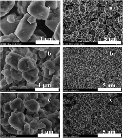 |
| | Fig. 3 SEM images of samples (a) NaY, (b) NH3-CTAB-c and (c) NaOH-CTAB-c. | |
 |
| | Fig. 4 TEM images of samples (a–c) NH3-CTAB-c and (d–f) NaOH-CTAB-c. | |
Further TEM images are given in Fig. 5 as to accurately clarify the porosity distribution in the ultramicrotomed sample NH3-CTAB-c. It clearly shows that small mesopores with uniform size around 2–3 nm distribute evenly in large scale in the zeolite particle (light dots), which is largely different from those core–shell structures combining zeolite Y with mesoporous MCM-41 or those meso-microporous composites.16 Besides the presence of uniform mesopores, distinct lattice fringes corresponding to zeolite crystalline structures can also be observed in the same particle from the magnified image in Fig. 5b. The co-occurrence of mesoporosity and zeolite crystalline structure in the same particle also exhibits that sample NH3-CTAB-c was not just composed of physical mixture of mesoporous MCM-41 solids with microporous zeolite Y particles.
 |
| | Fig. 5 TEM images of the ultramicrotomed sample NH3-CTAB-c. | |
As recorded, hierarchically structured FAU zeolites can be prepared by post-treatment in many approaches, such as steaming treatment or steaming combining with acid leaching, alkaline leaching, desilication combining with re-crystallization in the presence of a pore-directing agent and surfactant-templated structure arrangement.21 Anyway, the formation of mesopores always asks for high Si/Al molar ratio. In the present procedure, lactic acid is utilized to dealuminate and increase the Si/Al molar ratio before alkaline treatment. As known, Lactic acid is a hydroxyl carboxylic acid and can coordinate with aluminum ions in the framework just like some other chelating agent, e.g. EDTA,54,55 citric acid56 and tartaric acid.51 After lactic acid treatment, the resultant sample HLA-HT owns apparent higher Si/Al molar ratios, both framework or bulk Si/Al molar ratios, than those of parent sample NaY, as listed in Table 1. Nevertheless, the removal of aluminum ions from the framework and subsequent formation of vacancies caused dramatically descending of the crystallinity. Furthermore, the bulk Si/Al molar ratio of sample HLA-HT is much higher than its framework Si/Al molar ratio indicating that some silicon-rich extra-framework species were occluded in the sample.57–59 Besides dealumination, exchange of extra-framework Na+ ions by protons takes place simultaneously. However, the removal of framework aluminum does not result in obvious emerge of mesostructures or significant increase in external surface area, as listed in Table 2. After alkaline treatment at high temperature of 150 °C, removal of amorphous Si-rich moieties would happen to sample HLA-HT to varied extents in different alkaline solutions, resulting in decrease of the bulk Si/Al molar ratio which can be detected by ICP-AES, whereas the crystallinities and framework Si/Al molar ratios determined through XRD patterns increase. This suggests that the decrease of bulk Si/Al molar ratio was fully caused by elimination of silicon-rich extra-framework species while the dissolving of zeolitic framework was inhibited since the aluminum ions in the framework may protect the zeolite crystalline structure from alkaline attack during the alkaline treatment.48 The minor increase of the framework Si/Al molar ratios for both of the samples are ascribed to the partial structure recovery by the silicon-rich extra-framework species during the hydrothermal treatment at high temperatures.
Starting from Y zeolite with low Si/Al molar ratios, Garcia-Martinez and co-workers43,46 once recorded an attempt to introduce mesostructures into the zeolite in a two-step method, namely citric acid washing pretreatment and alkaline treatment in the presence of pore directing agent (CTAB). As reported, acid washing pretreatment using dilute citric acid was essentially important for the formation of mesopores in the subsequent alkaline modification process. Varied from the lactic acid pretreatment process described herein, dilute citric acid washing just had some of the Si–O–Al bonds in zeolite framework open with the formation of Si–OH and/or Al–OH ligands. Minor removal of the aluminum ions and collapse of the zeolite crystalline structures can be observed. The formed Si–OH and/or Al–OH during acid washing pretreatment played a key role for accommodating the surfactant micelles and zeolite structure re-arrangement, thus formation of mesostructures. However, no structural Si/Al evolution or textural property details were given for the final mesostructured Y zeolites prepared from low Si/Al Y zeolites (CBV100 or CBV300) in the publications. Besides this, Verboekend et al.41 also applied acid pretreatment or coordination combining alkaline leaching method to introduce mesoporosity into low Si/Al Y zeolites. As demonstrated by the authors, individual acid or base treatment on low Si/Al Zeolite Y does not lead to apparent development of mesoporosity, similar to the results of lactic acid pre-modification presented herein. Notably, before desilication in alkaline medium, dealumination of low Si/Al Y zeolites by acid pre-treatment was indispensable to make the bulk Si/Al molar ratio (detected by inductively coupled plasma optical emission spectroscopy, ICP-OES) exceed 4 and weaken the protection effect of the framework aluminum ions toward silicon dissolution. Thus during the sequential base treatment, mesoporosity can be introduced by desilication with extra-framework Al species left in the porosity and as claimed the removal of Al-rich debris was beneficial for freeing the porosity and increasing the crystallinity. Although hierarchically structured Y zeolites with low Si/Al molar ratio can be synthesized through the sequential acid and base treatments, severe decrease of the crystallinities (<20%) of the final samples can be observed.
The dealumination–desilication process can also be inspected through Solid 29Si and 27Al MAS NMR spectra as shown in Fig. 6. The 29Si MAS NMR spectrum of the parent NaY sample shows typical five signals with Si(nAl) building units (n = 0–4) in the range of chemical shifts between −85 and −125 ppm5 while in the 27Al MAS NMR spectrum, only one peak positioned at about 61 ppm can be observed assigning to four-coordinated framework aluminum ions, which means that there are no extra-framework aluminum species in parent NaY. After lactic acid leaching, sample HLA-HT displays a spectrum with drastic changes in the shape and intensity of 29Si MAS NMR signals comparing with that of sample NaY. As can be seen that the peaks of Si(4Al), Si(3Al), and Si(2Al) structure units decrease in intensity whereas the intensities of peaks corresponding to Si(1Al) and Si(0Al) units increase which means the removal of aluminum ions firstly occurred in Al-rich framework in Y zeolite, especially in Si(2Al) and it is consistent with the results described by Yue et al.51 and Xie and co-workers56 when zeolite FAU or BEA was treated using hydrocarboxylic acids. Furthermore, broadening in the signal distributions also can be observed and a significant shoulder appears in the region between −108 and −115 ppm in the sample HLA-HT, which is corresponding to silicon-rich amorphous aluminosilicate and/or silica species.60 All these can prove that internal changes of the framework structure take place with the formation of new siliceous-rich extra-framework species and vacancies in zeolite structures when parent NaY was treated by lactic acid. Besides, the aluminum ions extracted from zeolite framework are mostly dissolved into the solution in the form of aluminum lactate coordinates instead of extra-framework aluminum species concluded in the pore structures of zeolite as the peak in 27Al NMR spectrum located at about 0 ppm ascribing to six-coordinated Al ions is very weak. After treatment in ammonium water solution, the sample NH3-CTAB-c displays a spectrum very similar to that of sample HLA-HT but with the intensity of peaks Si(3Al) and Si(2Al) further decreased whereas intensity of peak Si(1Al) increased and this is consistent with the increased framework Si/Al molar ratio as detected by XRD. The minor decrease of the bulk Si/Al listed in Table 1 may result from the dissolving of small portion of silicon-rich species attacked by ammonium water solution at 150 °C. Concurrently, silicon dissolution leads to more extra-framework aluminum species left in the zeolite structures which is similar with that claimed by Verboekend et al.41 and can also be proved by the 27Al NMR spectrum in Fig. 6II-c. It can be noticed that the intensity of the peak located at 0 ppm corresponding to six-coordinated aluminum ions is obviously strengthened comparing with that for sample HLA-HT in Fig. 6II-b. As for sample NaOH-CTAB-c prepared in NaOH solution, the spectrum (Fig. 6d) shows a largely different pattern comparing with that of sample HLA-HT (Fig. 6b). In the 29Si NMR spectrum of sample NaOH-CTAB-c, it clearly exhibits that the numbers of Si(1A1) units apparently decrease, giving rise to Si(2A1) and Si(3A1) units. Besides, differing from that in the spectrum for sample NH3-CTAB-c in Fig. 6Ic, the shoulder in the region between −108 and −115 ppm almost diminishes, suggesting that severe dissolving of silicon-rich species takes place during alkaline treatment in NaOH solution which results in distinct decrease of bulk Si/Al molar ratio as listed in Table 1. Furthermore, since the alkalinity of NaOH solution is strong enough, aluminum containing extra-framework species are also dissolved evidenced by the vanishing of the peak at about 0 ppm in the 27Al NMR spectrum in Fig. 6IId and this is not the same with that happened to sample NH3-CTAB-c. As the bulk Si/Al molar ratio is still slightly higher than the framework Si/Al molar ratio for the NaOH-CTAB-c as listed in Table 1, the silicon-rich amorphous species were not entirely dissolved with a small quantity still left in sample NaOH-CTAB-c, for example, the formed silicon-rich mesostructured debris shown in Fig. 4f.
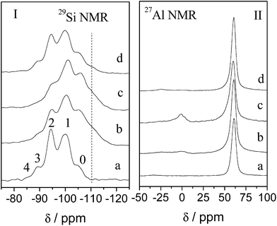 |
| | Fig. 6 29Si and 27Al NMR of samples before and after treatment: (a) NaY, (b) HLA-HT, (c) NH3-CTAB-c and (d) NaOH-CTAB-c. | |
During the alkaline treatment, fabrication of mesostructures by assembling amorphous Si-rich species around CTA+ micelles also takes place along with dissolution. The occlusion of organic CTA+ in the prepared samples can be proved by FT-IR spectra. Fig. 7 gives IR spectra of the parent NaY and the modified Y zeolite samples in acid/base solutions. It can be seen that all the samples display almost identical spectra which is typical for FAU-type zeolite, in which peaks centered at 1022 and 1145 cm−1 are ascribed to framework asymmetric stretching vibrations while peaks located at 794 and 723 cm−1 are corresponded to framework symmetric stretching vibrations and peaks at 582 cm−1 and 489 cm−1 to tetrahedral vibrations of double six-membered rings (D6R) and O–T–O bending vibrations, respectively.61 Besides the transmittance peaks attributing to FAU zeolite structures, some peaks positioning at 2854 and 2925 cm−1 ascribed to –CH2 and –CH3 stretching vibrations, peaks in the range of 1300–1500 cm−1 ascribed to C–H bending vibrations and weak peak around 910 cm−1 to C–C stretching vibrations can be observed only in the spectra of sample NH3-CTAB-a and NaOH-CTAB-a, which are caused by CTA+ moieties occluded in the samples. The absence of peaks in such districts for sample HLA-HT further proves the formed aluminum lactate coordinate was removed and little lactic acid residues was included in the sample during treatment.
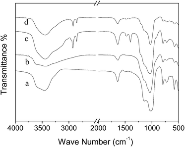 |
| | Fig. 7 FT-IR spectra of (a) parent NaY zeolite, (b) HLA-HT, (c) NH3-CTAB-a and (d) NaOH-CTAB-a. | |
Aiming to estimate the amount of organic CTA+ moieties embedded in different zeolite samples, TG-DTG curves were recorded as depicted in Fig. 8. It shows that for sample NaY zeolite without any treatment, the main weight loss, about 17–18% of the total weight ascribing to removal of the physical adsorbed water, takes place in the temperature range of 25–200 °C. As the temperature increases, no further obvious weight loss can be detected. Whilst for sample NH3-CTAB-a and NaOH-CTAB-a, the thermal evolution processes are very similar to each other. Combined with DTG curves, it is easy to divide the weight loss process of the samples into three regions and the relative weight losses in each region are not identical. Taking sample NaOH-CTAB-a as an example, it can be seen that the first weight loss step, about 10% of the total weight, also proceeds in the temperature range of 25–200 °C. Furthermore, another two weight losses in the range of 200–420 °C and 420–700 °C can be observed which can be ascribed to decomposition of organic CTA+ clusters and combustion of the small chemical residuals and dehydration by silanol polymerization. Amongst the three samples, apparently more water is physically adsorbed in NaY zeolite because of its higher hydrophilic zeolite nature due to large amount of Al ions in the framework62 and the presence of CTA+ in the other samples may also inhibit the occlusion of water molecules in the zeolite pores. Comparing the weight losses of sample NH3-CTAB-a with that of sample NaOH-CTAB-a, it can be noted that the amount of CTA+ moieties occluded in sample NaOH-CTAB-a is larger than that in sample NH3-CTAB-a, which does not match well with the results of N2 adsorption experiment that sample NH3-CTAB-a owns superior mesostructures, e.g. larger external specific surface area and higher mesopore volume as shown in Table 2. So it may be deduced that the proportion of mesostructures in the samples has no direct relationship with the occluded CTA+ amount. Yet, the addition of CTAB in the alkaline treatment process, especially in NaOH solution, is necessary as to direct the formation of mesostructures and inhibit the emerging of zeolite P (ESI Fig. S1†), for zeolite P can easily form during the crystallization or post-treatment process in high alkaline solutions.
 |
| | Fig. 8 TG-DTG curves of (a) parent NaY zeolite and (b) NH3-CTAB-a and (c) NaOH-CTAB-a. | |
 |
| | Fig. 9 NH3-TPD curves of samples (a) NH3-CTAB-cat, (b) NaOH-CTAB-cat and (c) HY. | |
As recorded, the introduction of mesopores into the microstructured zeolite in the presence of CTAB always proceeds in different ways according to different groups. Based on the facts that the preservation of zeolite framework Si/Al molar ratio and almost 100% of solid recovery after alkaline treatment, Garcia-Martinez et al. once proposed a surfactant-assisted crystal rearrangement mechanism to illustrate the mesopores generation process in which Si–O–Si bonds in the zeolite structures were attacked firstly by alkaline and broken with the formation of negatively charged sites. The resultant negatively charged sites can react with positively charged surfactants through electrostatic interactions. And finally, the occluded surfactant cations assembled together with the formation of micelles within the zeolite crystals and made the zeolite microstructures rearrange so as to form mesopores around the micelles.43 Otherwise, Ivanova and co-workers demonstrated another possibility for the formation of micro-mesoporous hierarchical materials through post-treatment of zeolite, in which zeolite dissolution and re-assembly were involved.16 As stated, zeolite with high enough Si/Al molar ratio firstly dissolved under alkaline circumstances to some extent leading to partial zeolite structure destruction and extraction of zeolitic fragments. Then, the zeolitic fragment dispersed in alkaline solutions may re-assemble together around CTA+ micelles with the generation of mesoporous structures. Furthermore, depending on the zeolite dissolution degree, the formed mesostructures may either just cover the zeolite surface to generate micro-mesostructured composites, or exist apart from zeolite with the generation of micro/mesoporous dual-phase mixtures, or completely immerses the residual zeolite. The dissolution and re-assemble mechanism was also verified by Perez-Ramirez and co-workers when CTA+ was used as pore-directing agent in the post-treatment of zeolites.40,63 According to the SEM images of sample NaOH-CTAB-c shown in Fig. 3c, displaying mixtures of large zeolite-like bulks and small pieces of debris, we can conclude that the formation of mesostructures in sample NaOH-CTAB-c may proceed following the way proposed by Ivanova and co-workers.16 On the other hand, the low solid yield (75%) after alkaline treatment in NaOH solution without addition of CTA+ also proves the dissolution process as listed in ESI Table S1.† When ammonium water solution was utilized instead in the absence of CTA+, high solid yield (97%) can be obtained due to the low alkalinity of the solution, that is to say, the mesostructures in sample NH3-CTAB-c can not form in the dissolution-reassembly way, at least not possible in large scale as shown in Fig. 4c. Therefore, the mesostructures in zeolite NH3-CTAB-c were alternatively directed in a structure-rearrangement procedure caused by the weaker silicon dissolution ability.
In order to elucidate the impact of the co-existence of micro-mesoporous structures on the diffusion of large organic molecules, acetalization of cyclohexanone with glycol or pentaerythritol were applied as probe reactions. As a comparison, industrial H+-type Y zeolite, microporous HY (textural properties as listed in Table 2) was also used as a catalyst in the reactions. As shown in Fig. 9 is the NH3-TPD curves of the three different catalyst samples. Amongst them, sample HY owns the largest amount of acid sites because of its highest crystallinity of zeolite structures. Generally, the acidity decreases apparently with a decrease in the zeolite crystallinity despite the similar Si/Al molar ratio. When used in the acetalization reaction of cyclohexanone with glycol, the three catalyst samples own almost the same reactivity as shown in Fig. 10a, since the product has a relative small molecular size and its diffusion in zeolite Y is not constrained. With increasing the reaction duration, the conversion of cyclohexanone is increased slightly as shown in Table 3, regardless of the catalyst nature used. When the catalytic reaction proceeds under the otherwise same condition using pentaerythritol instead of glycol, the conversion of cyclohexanone with pentaerythritol is decreased comparing with that with glycol. But comparing the three catalyst samples, HY displays the worst performance in acetalization of cyclohexanone with pentaerythritol, because the molecular size of the product is too large to diffuse out from the inner reactive sites in the zeolite structures, consistent with the results reported elsewhere.52 While the reactivities of catalysts NaOH-CTAB-cat and NH3-CTAB-cat lie in the same level with cyclohexanone conversion almost the same, even though catalyst NaOH-CTAB-cat owns a little higher cyclohexanone conversion in the reaction as demonstrated in Fig. 10 and in Table 3.
 |
| | Fig. 10 Comparative catalytic performance of microporous HY zeolites and hierarchically structured Y zeolites in Acetalization of Cyclohexanone with (I) glycol and (II) pentaerythritol. | |
Table 3 Catalytic performances in acetalization of cyclohexanone with glycol and pentaerythritol
| Catalysts |
Conv.a/% |
Conv.b/% |
| 0.5 h |
1 h |
2 h |
1 h |
2 h |
4h |
| Conversion of cyclohexanone after acetalization with glycol. Conversion of cyclohexanone after acetalization with pentaerythritol. |
| NaOH-CTAB-cat |
68.4 |
69.1 |
72.6 |
31.8 |
35.0 |
34.4 |
| NH3-CTAB-cat |
67.3 |
69.2 |
71.8 |
28.1 |
33.5 |
33.7 |
| HY |
66.9 |
67.7 |
72.2 |
12.3 |
17.2 |
23.6 |
4. Conclusions
Hierarchically structured Y zeolites were prepared by post-synthetic strategy, where parent NaY zeolite was sequentially treated by lactic acid solution and an alkaline solution containing cetyltrimethyl ammonium bromide (CTAB). Lactic acid pre-modification of NaY is vitally important because it may dealuminate the zeolite framework and result in the formation of silicon-rich amorphous species offering nutrients for the formation of mesoporosity. During alkaline treatment in the presence of surfactant CTA+ micelles, mesoporosity can be successfully introduced into the NaHY zeolites while the microporous structures are well preserved. By varying the alkaline solution used, the textural properties of the final products are different because of different silicon solubility and different mesopore formation mechanisms are discussed: after treated in ammonium solution, mesostructured zeolite was formed in structure re-arrangement mechanism proposed by Garcia-Martinez and co-workers,21,43 otherwise, mesostructures were introduced through dissolution-reassembly procedure described by Ivanova's group16 when treated in NaOH solution. The hierarchically structured Y zeolites exhibit much better performances in the acetalization reaction of cyclohexanone with pentaerythritol than conventional Y zeolites while the conventions of cyclohexanone are almost identical when reacted with glycol. This phenomenon could be attributed to the enhanced diffusion ability of large sized guest molecules through the combination of mesoporosity and microstructures comparing with pure microporous Y zeolites.
Acknowledgements
This work is supported by National Key Technology R&D Program (no. 2012BAE05B02) and National Science Foundation of China (20890124). And Prof. Wang thanks the Fundamental Research Funds for the Central Universities and the Program for New Century Excellent Talents in University (NCET-11-0145), Ministry of Education of China.
References
- D. W. Breck and R. E. Krieger, Zeolite molecular sieves: structure, chemistry, and use, 1984 Search PubMed
 .
. - J. Cejka, H. van Bekkum, A. Corma and F. Schueth, Introduction to Zeolite Molecular Sieves, Elsevier Science, 2007 Search PubMed .
- J. Čejka, N. Žilková and P. Nachtigall, Molecular Sieves: From Basic Research to Industrial Applications, Elsevier, 2005 Search PubMed .
- R. F. T. Stepto and R. Szostak, Molecular Sieves: Principles of Synthesis and Identification, Springer, 1998 Search PubMed .
- J. Weitkamp and L. Puppe, Catalysis and Zeolites: Fundamentals and Applications, Springer, 1999 Search PubMed .
- P. O'Connor, P. Imhof and S. J. Yanik, Catalyst assembly technology in FCC. Part I: A review of the concept, history and developments, Elsevier, 2001, pp. 299–310 Search PubMed .
- R. Sadeghbeigi, FCC Catalysts, in Fluid Catalytic Cracking Handbook, Butterworth-Heinemann, Oxford, 3rd edn, 2012, pp. 87–115 Search PubMed .
- G. M. Woltermann, J. S. Magee and S. D. Griffith, Commercial Preparation and Characterization of FCC Catalysts, Elsevier, 1993, pp. 105–144 Search PubMed .
- B. Liu, F. Chen, L. Zheng, J. Ge, H. Xi and Y. Qian, RSC Adv., 2013, 3, 15075–15084 RSC .
- T. C. Keller, S. Isabettini, D. Verboekend, E. G. Rodrigues and J. Perez-Ramirez, Chem. Sci., 2014, 5, 677–684 RSC .
- M. Zahmakıran, Y. Tonbul and S. Özkar, J. Am. Chem. Soc., 2010, 132, 6541–6549 CrossRef PubMed .
- W. Fu, L. Zhang, T. Tang, Q. Ke, S. Wang, J. Hu, G. Fang, J. Li and F.-S. Xiao, J. Am. Chem. Soc., 2011, 133, 15346–15349 CrossRef CAS PubMed .
- R. Chal, C. Gérardin, M. Bulut and S. van Donk, ChemCatChem, 2011, 3, 67–81 CrossRef CAS .
- A. Corma, Chem. Rev., 1997, 97, 2373–2420 CrossRef CAS PubMed .
- Y. Tao, H. Kanoh, L. Abrams and K. Kaneko, Chem. Rev., 2006, 106, 896–910 CrossRef CAS PubMed .
- I. I. Ivanova and E. E. Knyazeva, Chem. Soc. Rev., 2013, 42, 3671–3688 RSC .
- J. Perez-Ramirez, C. H. Christensen, K. Egeblad, C. H. Christensen and J. C. Groen, Chem. Soc. Rev., 2008, 37, 2530–2542 RSC .
- D. P. Serrano, J. M. Escola and P. Pizarro, Chem. Soc. Rev., 2013, 42, 4004–4035 RSC .
- V. Valtchev, G. Majano, S. Mintova and J. Perez-Ramirez, Chem. Soc. Rev., 2013, 42, 263–290 RSC .
- L. Tosheva and V. P. Valtchev, Chem. Mater., 2005, 17, 2494–2513 CrossRef CAS .
- K. Li, J. Valla and J. Garcia-Martinez, ChemCatChem, 2014, 6, 46–66 CrossRef CAS .
- Y. Tao, H. Kanoh and K. Kaneko, J. Phys. Chem. B, 2003, 107, 10974–10976 CrossRef CAS .
- A. Inayat, I. Knoke, E. Spiecker and W. Schwieger, Angew. Chem., Int. Ed., 2012, 51, 1962–1965 CrossRef CAS PubMed .
- J. Jin, C. Peng, J. Wang, H. Liu, X. Gao, H. Liu and C. Xu, Ind. Eng. Chem. Res., 2014, 53, 3406–3411 CrossRef CAS .
- G. Zhu, S. Qiu, J. Yu, Y. Sakamoto, F. Xiao, R. Xu and O. Terasaki, Chem. Mater., 1998, 10, 1483–1486 CrossRef CAS .
- B. A. Holmberg, H. Wang, J. M. Norbeck and Y. Yan, Microporous Mesoporous Mater., 2003, 59, 13–28 CrossRef CAS .
- W. Song, V. H. Grassian and S. C. Larsen, Chem. Commun., 2005, 2951–2953 RSC .
- P. Morales-Pacheco, F. Alvarez, L. Bucio and J. M. Domínguez, J. Phys. Chem. C, 2009, 113, 2247–2255 CAS .
- S. Mintova, N. H. Olson and T. Bein, Angew. Chem., Int. Ed., 1999, 38, 3201–3204 CrossRef CAS .
- Q. Li, D. Creaser and J. Sterte, Chem. Mater., 2002, 14, 1319–1324 CrossRef CAS .
- B. Wang, H. Z. Ma and Q. Z. Shi, Chin. Chem. Lett., 2002, 13, 385–388 CAS .
- B.-Z. Zhan, M. A. White, M. Lumsden, J. Mueller-Neuhaus, K. N. Robertson, T. S. Cameron and M. Gharghouri, Chem. Mater., 2002, 14, 3636–3642 CrossRef CAS .
- W. Lutz, D. Enke, W.-D. Einicke, D. Täschner and R. Kurzhals, Zeitschrift für anorganische und allgemeine Chemie, 2010, 636, 2532–2534 CrossRef CAS .
- W. Lutz, R. Kurzhals, G. Kryukova, D. Enke, M. Weber and D. Heidemann, Z. Anorg. Allg. Chem., 2010, 636, 1497–1505 CrossRef CAS .
- W. Lutz, R. A. Shutilov and V. Y. Gavrilov, Z. Anorg. Allg. Chem., 2014, 640, 577–581 CrossRef CAS .
- A. H. Janssen, A. J. Koster and K. P. de Jong, Angew. Chem., Int. Ed., 2001, 40, 1102–1104 CrossRef CAS .
- A. H. Janssen, A. J. Koster and K. P. de Jong, J. Phys. Chem. B, 2002, 106, 11905–11909 CrossRef CAS .
- K. P. de Jong, J. Zečević, H. Friedrich, P. E. de Jongh, M. Bulut, S. van Donk, R. Kenmogne, A. Finiels, V. Hulea and F. Fajula, Angew. Chem., 2010, 122, 10272–10276 CrossRef .
- K. P. de Jong, J. Zečević, H. Friedrich, P. E. de Jongh, M. Bulut, S. van Donk, R. Kenmogne, A. Finiels, V. Hulea and F. Fajula, Angew. Chem., Int. Ed., 2010, 49, 10074–10078 CrossRef CAS PubMed .
- D. Verboekend, G. Vilé and J. Pérez-Ramírez, Cryst. Growth Des., 2012, 12, 3123–3132 CAS .
- D. Verboekend, G. Vilé and J. Pérez-Ramírez, Adv. Funct. Mater., 2012, 22, 916–928 CrossRef CAS .
- J. Garcia-Martinez, Methods for making mesostructured zeolitic materials, US Patent. US20080138274, 2008 .
- J. Garcia-Martinez, M. Johnson, J. Valla, K. Li and J. Y. Ying, Catal. Sci. Technol., 2012, 2, 987–994 CAS .
- J. Garcia-Martinez, K. Li and G. Krishnaiah, Chem. Commun., 2012, 48, 11841–11843 RSC .
- B. Speronello, J. Garcia-Martinez, A. Hansen and R. Hu, Refinery Operations, 2011, 2, 1–6 Search PubMed .
- J. Garcia-Martinez, M. M. Johnson and l. Valla, Introduction of mesoporosity in low Si/Al zeolites, US 20100196263A1, 2010 .
- Z. X. Qin, B. J. Shen, X. H. Gao, F. Lin, B. J. Wang and C. M. Xu, J. Catal., 2011, 278, 266–275 CrossRef CAS PubMed .
- J. C. Groen, L. A. A. Peffer, J. A. Moulijn and J. Pérez-Ramírez, Chem.–Eur. J., 2005, 11, 4983–4994 CrossRef CAS PubMed .
- D. Verboekend and J. Perez-Ramirez, Catal. Sci. Technol., 2011, 1, 879–890 CAS .
- Z. Qin, B. Shen, X. Gao, F. Lin, B. Wang and C. Xu, J. Catal., 2011, 278, 266–275 CrossRef CAS PubMed .
- M. B. Yue, T. Xue, W. Q. Jiao, Y. M. Wang and M.-Y. He, Microporous Mesoporous Mater., 2012, 159, 50–56 CrossRef CAS PubMed .
- W. H. Fu, Y. M. Wang and M. Y. He, RSC Adv., 2013, 3, 18519–18528 RSC .
- Y. Lv, X. Qian, B. Tu and D. Zhao, Catal. Today, 2013, 204, 2–7 CrossRef CAS PubMed .
- G. T. Kerr, J. Phys. Chem., 1968, 72, 2594–2596 CrossRef CAS .
- G. T. Kerr, J. Phys. Chem., 1969, 73, 2780–2782 CrossRef CAS .
- X. Zaiku, C. Qingling, Z. Chengfang, B. Jiaqing and C. Yuhua, J. Phys. Chem. B, 2000, 104, 2853–2859 CrossRef .
- W. Lutz, H. Toufar, D. Heidemann, N. Salman, C. H. Ruescher, T. M. Gesing, J. C. Buhl and R. Bertram, Microporous Mesoporous Mater., 2007, 104, 171–178 CrossRef CAS PubMed .
- W. Lutz, R. Bertram, D. Heidemann, R. Kurzhals, C. Rüscher and G. Kryukova, Z. Anorg. Allg. Chem., 2011, 637, 75–82 CrossRef CAS .
- W. Lutz, D. Heidemann, R. Kurzhals and G. Kryukova, Z. Anorg. Allg. Chem., 2010, 636, 1361–1367 CrossRef CAS .
- J. Datka, W. Kolidziejski, J. Klinowski and B. Sulikowski, Catal. Lett., 1993, 19, 159–165 CrossRef CAS .
- H. G. Karge and E. Geidel, Vibrational Spectroscopy, in Molecular Sieves, Springer-Verlag, Berlin Heidelberg, 2004, pp. 52–54 Search PubMed .
- E. G. Derouane and S. M. Roberts, Catalysts for Fine Chemical Synthesis, Microporous and Mesoporous Solid Catalysts, Wiley, 2006, p. 47 Search PubMed .
- D. Verboekend, M. Milina, S. Mitchell and J. Pérez-Ramírez, Cryst. Growth Des., 2013, 13, 5025–5035 CAS .
Footnote |
| † Electronic supplementary information (ESI) available. See DOI: 10.1039/c4ra11042k |
|
| This journal is © The Royal Society of Chemistry 2014 |
Click here to see how this site uses Cookies. View our privacy policy here.