DOI:
10.1039/C4RA10312B
(Paper)
RSC Adv., 2014,
4, 58608-58614
Polypyrrole: FeOx·ZnO nanoparticle solar cells with breakthrough open-circuit voltage prepared from relatively stable liquid dispersions
Received
12th September 2014
, Accepted 22nd October 2014
First published on 22nd October 2014
Abstract
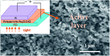
Organic hybrid solar cells with a large open-circuit voltage, up to above that of 1.5 V standard battery voltage, were demonstrated using blends of polypyrrole: Fe2O3·ZnO nanoparticles as active-layers. The cell active-layers were readily coated in open air from relatively stable liquid dark-color polypyrrole-based dispersions, which were synthesized using appropriate surfactants during the in situ polymerization of pyrrole with FeCl3 or both H2O2 and FeCl3 as the oxidizers. The performance of the cells depends largely on the synthesized blend phase, which is determined by the surfactants, oxidizers, as well as the reactant ratio. Only the solar cells fabricated from the stable dispersions can produce both a high open-circuit voltage (>1.0 V) and short-circuit current (up to 7.5 mA cm−2) due to the relatively uniform porous network nanomorphology and higher shunt to series resistance ratio of the active-layers. The cells also display a relatively high power-conversion efficiency of up to ∼3.8%.
1. Introduction
Polymer solar cells (PSCs) are hailed as a potential renewable and alternative energy source for electrical power due to their cost-effective preparation, ease and low temperature (<200 °C) processing, as well as ability to produce a large area of light active-layer coatings on both flexible and rigid substrates.1–3 Organic semiconductors also display a lower light reflection and higher light absorption coefficient than inorganic semiconductors.4 Hence, if the power-conversion efficiency (η) is largely improved, these “plastic” photovoltaic cells have the potential to become the counterparts of inorganic solar cells in the commercial market.5,6 In recent years, promising improvements of η to 3–9% for organic PSCs have been reported.5–7 However, more work has to be performed to further improve the efficiency for the realization of practical commercial applications.3,8 Hence, finding more suitable ways to increase the device efficiency, η, is required. Since η is the product of the short current (Jsc), open circuit voltage (Voc), and field factor (FF), approaches to improve the efficiency involve increasing these components. Most of the progress made nowadays in device efficiency is based on the improvement of Jsc and FF,6,7 with the largest reported Jsc and FF of up to ∼20 mA cm−2 and 85%,9,10 respectively, for organic devices. Further increase in FF will be marginal. Furthermore, it is also difficult to improve the Jsc significantly as the current density is limited by the intrinsic properties (e.g., charge carrier density, carrier mobility) and structures (e.g., charge transportation channels) of the large molecule-based devices.11 However, polymers have the potential to produce or bear voltages comparable or higher than inorganic semiconductors.12 This provides another means for improving the power-conversion efficiency by increasing the Voc while keeping the Jsc at a relatively high level. In addition, individual photovoltaic cells with a large voltage (e.g. ≥1 V or standard 1.5 V) output can also replace complex multiple cells in unique applications for precise and compact electrical or electronic devices.13 As such, various technical approaches6,14 are explored to improve Voc by numerous polymer blends (e.g., poly[2-methoxy-5-(20-ethyl-hexyloxy) and 1,4-phenylenevinylene] (MEH-PPV)15), in particular, using hybrids of electroactive polymers and inorganic semiconductors (e.g., ZnO, ZnS).16,17 Despite the significant progress for improving the Voc to ∼1 V, certain challenges are still faced, such as the η is still ≪1%,14–17 and the active-layer-coating for these photovoltaic devices usually involves non-air ambience,18,19 which gives rise to a complex and relatively expensive fabrication process. Therefore, it is necessary to develop an organic solar cell with a large Voc and high Jsc through an easy and cost-effective coating process in open air.
In this work, by the use of Fe2O3·ZnO to replace the commonly used pure ZnO for improving the optical property18,20 and synthesizing relatively stable liquid polypyrrole:Fe2O3·ZnO nanoparticle dispersions to obtain uniform nanostructured porous networks of active-layers, blend PSC cells with a large Voc of up to 1.56 V and a power-conversion efficiency of ∼3.8% have been demonstrated. The PPy-based dispersions were prepared via the oxidation of pyrrole in the presence of appropriate surfactant stabilizer(s) (e.g., SDBS, PEG, dye, ethanol).
2. Experimental
2.1 Preparation of Fe2O3·ZnO nanoparticles (FZO NP)
Zinc acetylacetonate (0.5 mmol), iron(III) acetylacetonate (0.13 mmol), 1,2-hexadecanediol (2 mmol), and benzyl ether (20 ml) were mixed under magnetic stirring, and consequently heated to 200 °C for 2 h and refluxed at 300 °C for 1 h. The mixture was cooled down to room temperature. The black product was precipitated by adding ethanol (40 ml) and separated by centrifugation. The precipitate was then dissolved in hexane in the presence of oleic acid (1.0 mmol) and oleylamine (0.3 mmol), and subsequently precipitated by adding ethanol (25 ml) and centrifuging. The particles were re-dispersed again in hexane according to the ratio of 1 mg
:
10 ml. The detailed procedure was similar to that reported previously.21
2.2 Preparation of stable liquid PPy-based dispersions
Pyrrole [>98%, C4H5N,
, Merck-Schuchardt, Schuchardt, Germany] and surfactants, such as sodium dodecylbenzene sulfonate [SDBS, 80% CH3(CH2)11OSO3Na,
, SIGMA Chem. Co., St. Louis, Mo], water-soluble poly(vinyl alcohol) [PVA, 88% (C2H4O)x,
, Sigma-Aldrich Company, St. Louis, MO] and PEG [C2nH4n+2On+1,
,] were used for the preparation of stable aqueous PPy-based dispersions via oxidation. During the preparation, typically, a 10 ml aqueous mixture of pyrrole (0.04 M) and the surfactant(s) (e.g., 0.06 M SDBS or/and 0.03 M other types) were first prepared under vigorous stirring in an ice-bath. The reactant mixture was added gradually into 5 ml of 0.8 M H2O2 in an ice-bath under vigorous stirring. After stirring for 2 h, the solution was heated to 70–90 °C for about 1.5 h until bubbles stopped forming upon the complete decomposition of H2O2. It was then cooled to room temperature. 10 ml of 0.4 M (or higher) FeCl3 aqueous solution and 1 ml of a FZO NP–hexane mixture were consequently added dropwise into the solution. After stirring for about 20 min, the mixture was transferred into an ultrasonic bath where it was stirred for the next 2–20 h to allow the complete evaporation of hexane. Depending on the reactants, the relatively stable dispersions (without or with only a little deposit) ranging from a transparent light brown, dark green, to black color were obtained.3 In the event where only FeCl3 was used as the oxidizer, the addition of H2O2 was neglected. FeCl3, H2O2, and other surfactants (without indicating above) were purchased from Sigma-Aldrich Company (St. Louis, MO).
2.3 Fabrication and characterization of photovoltaic devices
Indium tin oxide (ITO)-coated glass anodes (20 Ω sq−1) were patterned for the easy construction of devices via wet-etching with concentrated HCl as etchant. After patterning, the substrates were pre-cleaned via sequential sonication in deionized water, acetone, and isopropanol for 10 min, respectively, and then dried by N2 current gas and treated by oxygen plasma for 15 min at 30 W in a plasma machine (Sce106, Anatech USA-SP 100, Hayward, USA). Active-layers, such as from a mixture of PPy·FZO NP dispersion and ethanol (CH3CH2OH), water-soluble black dye (Everzol Black B,
, Everlight Chemical Industrial Corporation, Taiwan), were then prepared by spin-coating on the patterned ITO (anode) surface at a spin speed of 500–2000 rpm. This was followed by slow drying in a vacuum oven at a temperature of ∼40 and 120 °C for 5 and 2 h, respectively. This procedure resulted in 100–250 nm of active-layers. Next, an aluminum (Al) cathode (∼200 nm in thickness) was thermally evaporated on each soft-baked film at a high vacuum of 1–3 × 10⁻⁴ Pa. The photovoltaic cells with an active device area of 0.2 cm2 were defined using a shadow mask on the film during the Al-electrode deposition, and possessed a structure composing of a blend film of conjugated PPy polymer donor and FZO NP acceptor, which were sandwiched between an ITO-positive electrode and Al-negative electrode with a low work function. Finally, the device was removed from the evaporator chamber for testing without protective encapsulation.
The morphologies and thicknesses of the films were measured using a Field Emission Scanning Electron Microscope (FESEM, ELS-7000, Elionix, Japan) with an accelerating voltage of 5–10 kV and a pressure of ≤2.8 × 10⁻⁴ Pa.22 The UV-visible absorption spectra were measured on a Hitachi U-3010 UV-vis spectrophotometer. All the UV-signals were integrated by setting the maximum peak value of the absorbance spectra as 1. The photocurrent density–voltage (J–V) characteristics of the photovoltaic devices, in the dark and under illumination with visible light, were measured on a programmable electrometer (model 238, Keithley Instruments) with AM 1.5G illumination from a Sciencetech solar simulator (model SS150W/SS300W, London, Canada). The measurements were carried out under ambient condition with an intensity of 80 mW cm−2. During the measurement, the ITO-substrate and Al-film electrodes were correspondingly connected to the positive and negative electrodes of the electrometer analyzer. The series resistance (Rs) of the active-layers was calculated from the inverse slope at V = Voc, while the shunt resistance Rsh was calculated from the inverse slope at V = 0 in the J–V curves under illumination. The conductivity of the active-layers of the photovoltaic devices was examined using the four-point-probe method with a Keithley 238 electrometer and power supply. The detailed procedure was similar to our previously reported method.3
3. Results and discussion
Organic blend PSCs with a large Voc and relatively high Jsc were prepared using relatively stable liquid PPy-based dispersions with a large bandgap, which were synthesized from the oxidation of pyrrole via a 2-step (using H2O2 and FeCl3 as the oxidizers consequently) or 1-step (using only FeCl3 as the oxidizer) procedure in the presence of at least one appropriate surfactant.
3.1 Selection of stable PPy-based dispersions for PSC fabrication
Despite considerable debate over the mechanism governing Voc in organic solar cells,23 it has been established that a large Voc for photovoltaic devices can be obtained using semiconductors of larger bandgaps.24 Thus, the preparation of PPy polymers was investigated in this work. Although semiconductors with small band gaps have been used as the active-layer to achieve a higher Jsc by harvesting a larger portion of the solar spectrum, these polymers decreased the Voc value of the devices. PPy-based PSCs possess a high Jsc of up to 18 mA cm−2 and large band gaps of 2.0–3.8 eV,5,25 which are higher than most of the organic semiconductors (e.g., P3HT, polyacetylene, poly(3-octylthiopehene)).16,26 To obtain a larger donor–acceptor interface area, hybrid cells were also fabricated here. From the viewpoint of the physical structure of these bulk heterojunction devices, if the reactant (e.g., charge donor and acceptor) components can be evenly dispersed into each other throughout the bulk, which results in less exciton lost due to the recombination before dissociation, the bulk heterojunction PSCs can achieve the optimal performance due to the continuous pathways for the holes and electrons to travel through the blend to the electrodes. It is difficult to prepare such blends using conductive polymers in the solid or suspension phase (containing considerable PPy deposit), and hence liquid PPy-based dispersions were synthesized in this investigation using the carefully selected surfactants.
3.2 Selection of surfactants for more stable PPy-based dispersions with optimal performance
Although PPy-based polymers in solid or suspension phases are usually prepared,1,27 the PSCs fabricated from the polymers in these phases were below optimal performance. A stable PPy-based dispersion was reported using only H2O2 as the oxidizer in the preparation.28 The performances of the resulting PSCs were poor as well, even while using different surfactant(s) (e.g., SDBS, dye, and PVA) as the stabilizer(s). This was mainly attributed to the poor absorption of UV-light for these as-synthesized light-color PPy-based blends. The curves (i) and (ii) in Fig. 1a show the low absorption peaks for the blends prepared in the absence and presence of the SDBS surfactant, while the J–V curve (i) in Fig. 2a depicts the quite low Jsc and Voc of <0.02 mA cm−2 and 0.6 V, respectively, obtained for the PSC prepared by using the SDBS surfactant. Moreover, some surfactants (e.g., the dye) also led to solid or suspension phase PPy-blends. Hence, to improve the PSC performance, H2O2 and FeCl3 oxidizers were used consequently via the 2-step oxidation in the synthesis of the PPy-based dispersions. The polymerization changed the dispersions from a transparent to dark green or black color (depending on the surfactant type), which significantly increased the UV light absorption in the range of 300–700 nm for the as-synthesized polymers. The curves (iii) and (iv) of Fig. 1a show these improvements in the wavelengths around 400 and 600 nm, as well as the integration of UV-signals for the polymers prepared in the absence and presence of the SDBS surfactant, respectively. With the improved light adsorption, the cell performance (the curve (i) of Fig. 2b) for the blend prepared in the presence of SDBS also increased, with the Voc and Jsc values of 1.0 V and 1.2 mA cm−2, respectively. Further investigation showed that relatively stable dark-color PPy-based dispersions could be synthesized as well using FeCl3 as the only oxidizer in the 1-step oxidation.3 For the preparation of stable PPy-based dispersions from either the 2-step or 1-step polymerization, a suitable surfactant was required to prevent the formation of solid or suspensions with a large quantity of deposits in the solution. For instance, the use of the SDBS surfactant in the 1-step oxidation also enhanced the stability of the prepared PPy-based blend, as only a small amount of deposits was formed at the bottom of the suspension. The UV light absorption for the as-synthesized blend also improved [Fig. 1b(i)]. To prepare stable PPy-based blends, Fe2O3·ZnO nanoparticles were chosen over commonly used pure ZnO nanoparticles due to their better optical property. The FZO NP–hexane was also limited to <5 ml in the mixture solution. The particles could be readily and uniformly doped in the PPy polymers due to the presence of the hydrophilic (–NH2, –COOH) and hydrophobic [CH3(CH2)7CH:CH(CH2)7–] functional groups from the oleic acid and oleylamine.21 The TEM image [Fig. 3b inset] shows that the doped particle size was 5–8 nm. After the stable blends were prepared, the performance of the PSC was further improved by optimizing the surfactant(s). For instance, using other suitable surfactants (e.g., PEG, dye) to replace SDBS in the 2-step oxidization, and using two surfactants in the 1-step oxidation. This optimization also adjusted the composition and improved the stability of the PPy-based blends. Most of the blends formed dispersions, with no or little deposits appearing after being sealed and stored at room temperature for tens of minutes or even several months.
 |
| Fig. 1 UV-vis curves of the PPy·FNO NP blends prepared from different oxidizers or surfactants. (a) By the use of H2O2 oxidizer in the (i) absence and (ii) presence of SDBS, and using H2O2 and FeCl3 oxidizers in the (iii) absence and (iv) presence of SDBS. (b) By the use of FeCl3 oxidizer only in the presence of (i–iv) SDBS, SDBS and PVA, PVA and ethanol, PVA and dye, respectively. | |
 |
| Fig. 2 Current versus voltage (J–V) characteristics of PPy·FZO NP solar-cells, in which PPy-based blends were prepared from different conditions: using (a) only (i) H2O2 or (ii) FeCl3 in the presence of SDBS; only FeCl3 with (iii) high or (iv) regular concentration of pyrrole in presence of SDBS and PVA; (b) H2O2 and FeCl3 in the presence of (i) (—) SDBS, (ii) ( ) PEG, and (iii) (—) dye. (c) only FeCl3 in the presence of (i) (—) SDBS and PEG, (ii) (—) PVA and dye, and (iii) ( ) PVA and ethanol, while the insets in (b) and (c) represent the corresponding J–V curves under a dark light. | |
 |
| Fig. 3 FESEM images of PPy active-layers prepared from different reactants, mainly containing: (a) FeCl3 and SDBS; (b) greater or (c) regular pyrrole concentration, FeCl3, SDBS and PVA; (d)–(f) H2O2, FeCl3, and SDBS or dye or PEG, respectively; (g) and (h) FeCl3, PVA and dye or PVA and ethanol, respectively. The inset of (b) is the TEM image (scale bar: 20 nm) of doped Fe2O3·ZnO nanoparticles in the PPy polymer. The scale bars in the FESEM images are 100 nm for (a–c) while 1 μm for (d–h). | |
The spectra in Fig. 1b(ii)–(iv) show the improved light absorption for the stable liquid dispersions. In particular, some surfactants (e.g., SDBS and PVA, ethanol and dye) usually produced two peaks of UV light absorption. Therefore, the Voc, Jsc, or FF factors of the PPy-based PSCs as-synthesized from the stable dispersions were significantly improved, which are shown in Fig. 2b and c. The J–V curves in Fig. 2b illustrate the effects of different surfactants (e.g., SDBS, PEG, and dye) on the photovoltaic cell performances, in which the PPy active-layers were prepared via the 2-step oxidation. The Jsc increased to 1.2–3.1 mA cm−2, while the Voc improved to the range of 1.0–1.3 V, which were significantly higher than the maximum values (0.50–0.93 V) reported so far for most organic solar cells.1,5,14,15 Furthermore, the effects of using two surfactants, such as SDBS and PVA, SDBS and dye, and ethanol and PVA were also investigated during the 1-step oxidation polymerization. The curves in Fig. 2a(iv) and c(i)–(iii) show that the complex surfactants significantly improved the performance of the prepared photovoltaic cells, compared to that from the single SDBS surfactant [shown in Fig. 2a(ii)]. In particular, a breakthrough Voc of 1.56 V was achieved, which was higher than the standard battery voltage of 1.5 V and almost twice those of most organic photovoltaic cells reported to date. A high Jsc of 6.2 mA cm−2 was also attained for the photovoltaic cell prepared from the relatively stable PPy-based dispersion in the presence of PVA and ethanol surfactants. A power-conversion efficiency of 3.8% was achieved as well. The improved performance for this PSC compared to other PSCs was due to its relatively high density and wide UV light absorption [Fig. 1b(iii)]. Thus, suitable surfactant(s) in the reactants improved the stability and light absorption of the PPy-based dispersions, consequently enhancing the performances of the photovoltaic cells. Notably, as the ITO-substrate and Al-film electrode of the PSCs were connected to the positive and negative electrodes of the electrometer, respectively, the illuminating currents measured were usually negative in value, and the J–V curves were located at the fourth quadrant of coordinate axis. The kink that appeared in the J–V curve was associated with the carrier accumulation, which altered the distribution of the electric field inside the device. The imbalance of the charge carrier mobility, defects or dipoles at the interface, energy barriers and low surface recombination rate of the cathode are also the plausible reasons for the kink that appeared.29 For the reproducibility of the high Voc and other properties, further results from batches of PSCs revealed that besides suitable reactants and their ratios, the fabrication process (e.g., soft baking) was also crucial. After the active-layer was uniformly coated on an ITO substrate, the subsequent drying process should be carefully controlled. In the initial drying procedure for the coated liquid dispersion film, the temperature should be controlled at ∼40 °C for at least 5 hours for slowly removing all volatiles in the film. Then, the subsequent drying temperature should be gradually increased to 120 °C and the baking was kept till the PPy polymer was completely dried. An extremely short time or extremely high temperature (e.g., >60 °C) at the initial baking and extremely high increasing rate (e.g., >2 °C minute−1) for the subsequent baking temperature would cause a nano-/micro-cracked or pelt film (due to the quickly accumulated internal stress), instead of an even compact active-layer. The film with a cracked morphology or pelt layer consequently led to the poorer performance or reproducibility of the PSC, which will be elaborated in the following sections.
3.3 Root causes of the physical phase effect of the PPy·FNO NP blend to the PSC performance
The above mentioned investigations showed that with the selection of different suitable oxidizers or surfactants to produce stable PPy-based dispersions, PSCs were achieved with larger Voc, higher Jsc as well as FF, which was difficult to be attained with the PSCs prepared from solid or suspension PPy blends. This phenomenon was further verified with PSCs prepared from the PPy·FNO NP suspension and dispersion. These two blends were prepared from the same reactants (e.g., pyrrole, FeCl3, SDBS, PVA) of different compositional ratios. During the syntheses of the PPy-based blend, if the addition of pyrrole was too high (e.g., >0.1 M in the first mixture solution), the prepared blend was a suspension (instead of stable dispersion) and contained a huge amount of precipitates. The performance comparison for the two different PSCs, prepared from the suspension and dispersion blends, is illustrated in Fig. 2a(iii) and (iv), respectively. The PSC from the suspension displayed an almost non-photovoltaic property, whereas the PSC fabricated from the stable PPy-based dispersion possessed a Voc of 1.18 V and a Jsc of 2.7 mA cm−2. This dispersion was prepared utilizing a regular concentration of pyrrole (<0.08 M in the first mixture solution during the blend preparation), as such, the phase of the blends significantly influenced the performance of the synthesized photovoltaic cells, and the phase could be determined by both the types and ratios of the reactants. This phenomenon is attributed to the fact that the different physical phases of the blends affected the coating uniformity, internal structures, and nanomorphologies of the active-layers. Due to fluidity of the PPy-based polymers, the liquid dispersions not only allowed a large area (e.g., on a 6′′ ITO substrate) of thin stable active-layer to be prepared readily by spin- or blade-coating in open air at room temperature, but also produced relatively uniform porous-network structures after slow drying. This coating quality is much better than those from the suspensions. The FESEM image in Fig. 3a shows the poorer surface morphology of a PSC active-layer fabricated from the suspension using the FeCl3 oxidizer and SDBS surfactant. Fig. 3b and c show the comparison of the two active-layers prepared from the suspension and dispersion of the same reactants (pyrrole, FeCl3, SDBS, PVA). The active-layers [Fig. 3a and b] prepared from the two suspensions with different components were flat nano-cracked films, which contained bloc-shape components without uniform porous networks. Conversely, the active-layers fabricated with the dispersions, either from the 2-step oxidation using H2O2 and FeCl3 or 1-step oxidation using FeCl3, were compact nanoporous 3-dimensional networks without nano-cracks. The pore size varied with the blend compositions. Fig. 3c–h show the morphologies of the active-layers prepared from different dispersions using different oxidizers and surfactants. Thus, the different nanomorphologies of the active-layers largely influenced the UV light absorption and performance of the PSCs. For the uniform porous network films, the relative intensity and spectrum range of UV light absorption were improved significantly, because of the changed components as well as more UV photons being confined within the pores of the film instead of being reflected away. Therefore, the porous nanomorphology partially compensated the narrow light adsorption spectra due to the large band-gap of the PPy polymer. As a result, the uniform porous nanostructures led to the improved performance of the photovoltaic cells (Fig. 2b and c). In addition, the chemical stability of the PPy-based polymers ensured that the performances of the solar cells did not deteriorate over time. For example, the J–V curves in Fig. 2c show that the three PSCs, which were stored in a dry box for three weeks after preparation, still performed with similar results compared to the PSC in Fig. 2a(iv), which was also prepared from the FeCl3 oxidizer but measured as soon as its fabrication was completed.
Furthermore, the different reactants and their respective molar ratios also determined the conductivity, shunt resistance Rsh, and series resistance Rs of the active-layers. The data in Table 1 shows the physical properties of the PSCs prepared under different conditions. The conductivity of the active-layers fabricated from the dispersions was ∼0.86 Ω cm−1, which was much larger than that (∼10−3 Ω cm−1) from most of the PPy-based suspensions with a huge amount of precipitates. This suggested that the charge mobility of the active-layers prepared from the liquid dark-color dispersions was much higher than that from the suspensions. Furthermore, the PPy·FNO NP blends prepared from the stable dispersions have a larger Rsh and lower Rs, therefore a higher Rsh/Rs ratio as compared to the blends prepared from the suspensions. Representing the ohmic-loss due to the diode leakage currents from recombination and pinholes in the photovoltaic device,30 the shunt resistance Rsh, which does not contribute to the diode, should be high as possible to minimize the current leakage. Since the nano-cracked and non-uniform component active-layers gave rise to a low Rsh (shown in Table 1), the PSCs prepared from the suspensions were poor in performance. Moreover, the series resistance Rs of the active-layer represents the ohmic-loss at the surface of cell. Despite not directly contributing to the Voc, the Rs should be small to prevent the exponential diode from increasing to an infinitely large current and minimize electrical power loss,1,30 which is caused by the resistance limiting the current in the device. Thus, a small Rs and high Rsh (viz., a high Rsh/Rs ratio) will significantly improve the Voc and other performances. Therefore, due to the higher Rsh/Rs ratios, the PPy-based PSCs prepared from the relatively stable dark-color dispersions displayed the larger Voc and better performance, contrary to those fabricated from most PPy suspensions.
Table 1 Properties of the PPy active-layers prepared from different blends
Blend |
Oxidizer used |
Surfactant used |
Rs (Ω) |
Rsh (Ω) |
Rsh/Rs |
Jsc (mA cm−2) |
Voc (V) |
FF (%) |
η (%) |
Dispersion |
H2O2 |
— |
2.0 × 10⁴ |
2.2 × 10⁴ |
1.1 |
0.02 |
0.28 |
36.0 |
0.0 |
Suspension |
H2O2, FeCl3 |
— |
9.8 × 10² |
1.2 × 10² |
0.1 |
0.49 |
0.98 |
30.6 |
0.1 |
Dispersion |
H2O2 |
SDBS |
2.2 × 10⁴ |
6.0 × 10⁴ |
3 |
0.01 |
0.58 |
23.5 |
0.0 |
Suspension |
FeCl3 |
SDBS |
5.5 × 10² |
4.3 × 10² |
0.8 |
0.9 |
1.15 |
12.5 |
0.2 |
Suspension |
FeCl3 (much Py) |
SDBS, PVA |
6.8 × 10⁴ |
3.1 × 10⁴ |
0.5 |
0.02 |
1.11 |
12.8 |
0.0 |
Dispersion |
FeCl3 |
SDBS, PVA |
1.5 × 10² |
5.2 × 10² |
3 |
2.7 |
1.18 |
28.5 |
1.1 |
Dispersion |
H2O2, FeCl3 |
SDBS |
3.1 × 10² |
3.4 × 10³ |
11 |
1.3 |
1.04 |
33.0 |
0.5 |
Dispersion |
H2O2, FeCl3 |
PEG |
75 |
1.7 × 10³ |
23 |
3.1 |
1.16 |
26.9 |
1.2 |
Dispersion |
H2O2, FeCl3 |
Dye |
81 |
2.0 × 10³ |
25 |
2.0 |
1.28 |
38.0 |
1.2 |
Dispersion |
FeCl3 |
SDBS, PEG |
1.2 × 10² |
4.5 × 10² |
4 |
3.8 |
1.18 |
25.3 |
1.4 |
Dispersion |
FeCl3 |
PVA, dye |
55 |
3.2 × 10² |
6 |
7.1 |
1.20 |
32.0 |
3.4 |
Dispersion |
FeCl3 |
PVA, ethanol |
1.3 × 10² |
6.2 × 10² |
5 |
7.6 |
1.56 |
25.5 |
3.8 |
Although a large Voc of ≥1.0 V (Fig. 2) has been attained in most of our prepared PPy PSCs, the FF factor and Jsc are lower than certain reported PPy-dye sensitized solar cells.5,18 This is due to the relatively lower conductivity for the synthesized PPy-based blends, which limited the charge mobility. This issue will be addressed in our next development phase.
4. Conclusions
In summary, we have demonstrated an approach for preparing organic photovoltaic devices with a large breakthrough open-circuit voltage of 1.65 V using a relatively stable liquid dark-color PPy-based dispersion as the active-layer. Suitable surfactants behaved as stabilizers in the preparation of these stable dispersions and modified the property and morphology of the active-layers, and hence the field factor, short circuit current, and open circuit voltage of the PSC devices were significantly improved. Although the efficiency of the prepared solar cells was not comparable with commercial requirements, this preparation method revealed a potential way to achieve an improved power-conversion efficiency for practical use.
References
- P. Würfel, Physics of solar cells: from basic principles to advanced concepts, John Wiley & Sons, 2009 Search PubMed.
- R. J. Komp and J. Perlin, Practical photovoltaics: electricity from solar cells, Aatec Publications, 3rd edn, 1995 Search PubMed.
- B. Y. Zong, P. Ho and S. C. Wuang, Mater. Chem. Phys., 2014, 1–8, DOI:10.1016/j.matchemphys.2014.09.058, http://www.sciencedirect.com/science/article/pii/S0254058414006403.
- Q. F. Zhang, E. Uchaker, S. L. Candelaria and G. Z. Cao, Chem. Soc. Rev., 2013, 42, 3127–3171 RSC.
- B. E. Hardin, H. J. Snaith and M. D. McGehee, Nat. Photonics, 2012, 6, 162–169 CrossRef CAS.
- G. J. Zhao, Y. J. He and Y. F. Li, Adv. Mater., 2010, 22, 4355–4358 CrossRef CAS PubMed.
- J. D. Servaites, S. Yeganeh, T. J. Marks and M. A. Ratner, Adv. Funct. Mater., 2010, 20, 97–104 CrossRef CAS.
- C. S. Ferekides and D. L. Morel, Process development for high VOC CdTe solar cells. Subcontract report NREL/SR-5200-51605, University of South Florida Tampa, Florida, May 2011 Search PubMed.
- D. J. Burke and D. J. Lipomi, Energy Environ. Sci., 2013, 6, 2053–2066 CAS.
- W. Tress, K. Leo and M. Riede, Adv. Funct. Mater., 2011, 21, 2140–2149 CrossRef CAS.
- M. Wright and A. Uddin, Sol. Energy Mater. Sol. Cells, 2012, 107, 87–111 CrossRef CAS PubMed.
- J. Rostalski and D. Meissner, Sol. Energy Mater. Sol. Cells, 2000, 63, 37–47 CrossRef CAS.
- M. Taguchi, A. Terakawa, E. Maruyama and M. Tanaka, Prog. Photovoltaics, 2005, 13, 481–488 CAS.
- H. Y. Chen, J. H. Hou, S. Q. Zhang, Y. Y. Liang, G. W. Yang, Y. Yang, L. P. Yu, Y. Wu and G. Li, Nat. Photonics, 2009, 3, 649–653 CrossRef CAS.
- M. Bredol, K. Matras, A. Szatkowski, J. Sanetra and A. Prodi-Schwab, Sol. Energy Mater. Sol. Cells, 2009, 93, 662–666 CrossRef CAS PubMed.
- H. l. Yip and A. K. Y. Jen, Energy Environ. Sci., 2012, 5, 5994–6011 CAS.
- A. Duarte, K. Y. Pu, B. Liu and G. C. Bazan, Chem. Mater., 2011, 23, 501–515 CrossRef CAS.
- M. GrÄtzel, Acc. Chem. Res., 2009, 42, 1788–1798 CrossRef PubMed.
- E. J. W. List, C. H. Kim, J. Shinar, A. Pogantsch, G. Leising and W. Graupner, Appl. Phys. Lett., 2000, 76, 2083–2085 CrossRef CAS PubMed.
- M. Açıkgöz, M. D. Drahus, A. Ozarowski, J. van Tol, S. Weber and E. Erdem, J. Phys.: Condens. Matter, 2014, 26, 1558031–1558039 CrossRef PubMed.
- B. Y. Zong, G. C. Han, Y. K. Zheng, L. H. An, T. Liu, K. B. Li, J. J. Qiu, Z. B. Guo, P. Luo, H. M. Wang and B. Liu, Adv. Funct. Mater., 2009, 19, 1–7 CrossRef.
- B. Y. Zong, J. Y. Goh, Z. B. Guo, P. Luo, C. C. Wang, J. J. Qiu, P. Ho, Y. J. Chen, M. S. Zhang and G. C. Han, Nanotechnology, 2013, 24, 2453031–2453039 CrossRef PubMed.
- W. J. Potscavage, A. Sharma and B. Kippelen, Acc. Chem. Res., 2009, 42, 1758–1767 CrossRef CAS PubMed.
- V. Shaktawat, N. Jain, R. Saxena, N. S. Saxena, T. P. Sharma and J. Optoelectron, Adv. Mater., 2007, 9, 2130–2132 CAS.
- O. A. Andreeva, L. A. Burkova, M. A. Smirnov and G. K. El’yashevich, Polymer Sci. B, 2006, 48, 331–334 CrossRef.
- E. J. W. List, C. H. Kim, A. K. Naik, U. Scherf, G. Leising, W. Graupner and J. Shinar, Phys. Rev. B: Condens. Matter Mater. Phys., 2001, 64, 155204–155215 CrossRef.
- J. Nelson, The Physics of solar cells (properties of semiconductor materials), Imperial College Press, 2003 Search PubMed.
- V. Bocchi, L. Chierici and G. P. Gardini, Tetrahedron, 1970, 26, 4073–4082 CrossRef CAS.
- W. Tress, A. Petrich, M. Hummert, M. Hein, K. Leo and M. Riede, Appl. Phys. Lett., 2011, 98, 063301–063303 CrossRef PubMed.
- S. Yanagina, Y. H. Yu and K. Manseki, Acc. Chem. Res., 2009, 42, 1827–1838 CrossRef PubMed.
Footnote |
† Now working in Robert Bosch (SEA) Pte Ltd. |
|
This journal is © The Royal Society of Chemistry 2014 |
Click here to see how this site uses Cookies. View our privacy policy here.