
Nanomaterials via solution combustion synthesis: a step nearer to controllability
Wei Wen
a and
Jin-Ming Wu
*b
aCollege of Mechanical and Electrical Engineering, Hainan University, Haikou 570228, P. R. China
bState Key Laboratory of Silicon Materials, Key Laboratory of Advanced Materials and Applications for Batteries of Zhejiang Province, Department of Materials Science and Engineering, Zhejiang University, Hangzhou 310027, P. R. China. E-mail: msewjm@zju.edu.cn
First published on 30th October 2014
Abstract
Solution combustion synthesis (SCS) is a worldwide adopted technique to synthesize nanomaterials, especially for oxides, because of its simplicity, energy and time-effectiveness, and low cost. The general difficulty encountered in SCS is the controllability over phases and morphologies of the products, which arises from the inherent rapid and uncontrollable combustion procedure. In this regard, the present work is devoted to review the recent progress on phase- and morphology-controlled SCS in detail. Besides the various metal oxides, SCS is now applicable to fabricate nanomaterials of metal phosphates, metal silicates, metal borates, metal sulfides, metals, and even alloys, through careful selection of solution compositions. Oxides with regular morphologies of flowers, belts, triangles, tubes, wires, and rods can be synthesized by SCS, in the presence of certain templates, or through a self-assembly procedure. The recent progress made on the synthesis of porous materials via SCS is summarized. SCS is also capable of growing metal oxide thin films at low temperatures, enabling the fabrication of low-cost and high-performance electronics on flexible plastic substrates.
 Wei Wen | Wei Wen obtained his Ph.D. degree in Materials Science and Engineering from Zhejiang University in 2014. Currently, he is an assistant professor at the College of Mechanical and Electrical Engineering, Hainan University. His work is devoted to wet-chemistry synthesis of nanostructured oxides and their functional applications. |
 Jin-Ming Wu | Jin-Ming Wu is a professor at the State Key Laboratory of Silicon Materials, Zhejiang University. In 1999, he obtained his Ph. D. degree in Materials Science from Zhejiang University. He worked as a VBL researcher in Okayama University, Japan during the year 2000-2002 and an Alexander von Humboldt research fellow in Max-Planck-Institute of Colloids and Interfaces, Germany, from 2006 to 2007. His work is devoted to nanostructured oxides for energy and environmental applications. |
1. Introduction
Nanomaterials have sparked worldwide interest because of their unique physical and chemical properties arising from their small dimensions when compared with those of their bulk counterparts. In industry, oxide powders are generally fabricated by high-temperature solid-state reactions, where the desired products are achieved simply by maintaining the solid mixture of reactants at a high temperature.1,2 Such a ceramic route is energy and time consuming, and the products are usually inhomogeneous, coarse, impure, and away from stoichiometry because of a big diffusion barrier resulted from the lack of molecular-level mixing. Combustion synthesis (CS) is just the choice to achieve a rapid and energy-efficient synthesis. A typical CS procedure utilizes a self-sustained exothermic reaction among well-mixed reactants to achieve the rapid and economical synthesis of particulate products. Up to 2008, CS has been adopted to fabricate more than 1000 kinds of oxide powders3 over more than 65 countries.4Based on the physical nature of the reactants and also reaction mediums, CS can be classified as self-propagating high temperature synthesis (SHS) and solution combustion synthesis (SCS).4–6 Various materials of oxides, carbides, nitrides, borides, and aluminides have been obtained by SHS, some of which have been commercialized successfully.7–9 In industry, ceramic-lined steel pipes have also been prepared by a centrifugal SHS.10 The reactants in conventional SHS are all in solid state, still suffering from an inhomogeneous mixing. The coarse initial powders (10–100 μm in size) and high reaction temperatures (>2000 K) result in products with low surface areas and coarse sizes.4,5 Additional treatments such as mechanical activation,11 intensive milling,12 or chemical dispersion4,13 are required after SHS to reduce the particle size, which increase the preparation steps and cost. On the contrary, SCS begins from an aqueous solution, which guarantees a molecular-level mixing of reactants. As a result, SCS serves as a promising route for rapid and direct synthesis of mass nanomaterials.
2. Solution combustion synthesis (SCS)
In 1988, Patil firstly reported the synthesis of Al2O3 using Al(NO3)3·9H2O and urea.14 A typical SCS relies on an exothermic reaction between an oxidizer, typically metal nitrates, like Al(NO3)3·9H2O, and an organic fuel such as urea. The driving force for lattice formations derives from the internal chemical energy. The temperature input for SCS is not high, which is required just to trigger the combustion reaction, rather than to provide a continuous energy input to form lattices as the case in conventional material fabrication routes. Various water-soluble organics containing large quantities of C and H are utilized as fuels, which facilitates the liberation of heat by combustion. Certain fuels, such as glycine, also form complexes with metal ions to improve the mixing level of the reactants.5,15 For example, citric acid bonds with metal ions to form stable chelate complex compounds; amino acids, such as glycine, bonds with metal ions to build very stable chelate complex compounds. The formation of complex helps to achieve a more homogeneous mixing and hence avoids segregations, which is beneficial for producing complex and multicomponent oxides.16Most of the solution combustion procedures involve a transition from solution to a colloidal sol and then to a gel, which are thus also termed as gel (or sol–gel) combustion. Based on the precursors utilized, the sol–gel method can be categorized into three types: hydrolysis-condensation of metal-alkoxides, the gelation route via concentration of aqueous solutions involving metal-chelates, and the Pechini method.17 Among them, the Pechini technique includes a combined process of metal complex formation and in situ polymerization of organics and is versatile for fabricating metal oxides with homogeneous multicomponents.17 A typical Pechini procedure involves the introduction of metal salts or alkoxides into an ethylene glycol solution that contains citric acid. The formation of citric complexes leads to a homogeneous mixing and avoids the separation of components at the later stage. The polycondensation of citric acid and ethylene glycol results in the polymer gel formation. A subsequent heating of the gel leads to the removal of the polymer matrix and the formation of the products with a good homogeneity. If metal nitrates are used, instead of the metal salts or alkoxides, as precursors, and fuels are used as complexing agents, the Pechini sol–gel routes would involve a combustion reaction during the final heating process.
In SCS, the phase, morphology, particle size and surface area of products can be altered to certain extents by adjusting the fuel, the fuel/oxidizer ratio, and the pH value of the solution.15,16 A higher combustion temperature during SCS usually results in improved crystallinity, larger grain size, more serious agglomeration, and lower specific surface area for the products. The propellant chemistry theory is usually used to calculate the stoichiometry of the fuel and oxidizer.18,19 Taking the combustion reaction between zinc nitrate and urea (CH4N2O) as an example, the elemental valency of Zn, C, H, N, and O is +2, +4, +1, 0, and −2, respectively. Accordingly, the oxidizing valency of zinc nitrate and the reducing valency of urea are −10 and +6, respectively. The equilibrium combustion reaction can be described as,

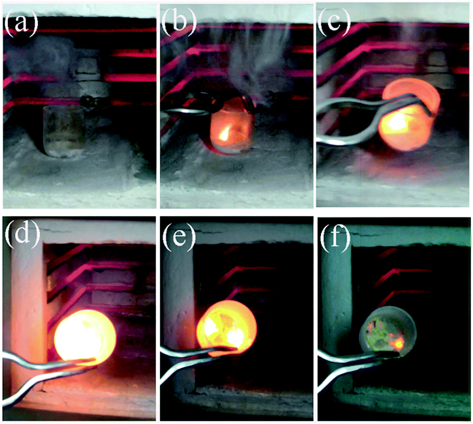 | ||
| Fig. 1 The typical combustion procedure in SCS: (a) after complete dehydration but before combustion, (b) ignition, (c–f) the combustion process after stopping energy input by taking the reactor out of the oven.20 Adopted from ref. 20, Copyright 2013, with permission from Elsevier. | ||
The advantages of SCS can be summarized as follows:15,16,21 (1) time and energy efficient; (2) the equipment is simple and the raw materials are usually less expensive; (3) a molecular level mixing for the raw materials; and (4) the composition of products can be tuned. Thanks to such merits, SCS has been adopted to fabricate various materials for many applications of catalysis,22–30 luminescent materials,31–36 fuel cells,37–39 energy conversion,40–42 and energy storage.43–46 Complicated Garnets are also widely synthesized by SCS.47–50 For example, Huczko et al. synthesized cerium-doped yttrium aluminum garnet by SCS.47 Recently, SCS is also applied to synthesize thin films of metal oxides.51–55 Fabrications of low-cost and high-performance electronics at low temperatures are thus possible with the help of SCS.51–55 A detailed description of SCS and its applications is out of the region of this review and the interested readers can refer to other reviews3–6,21,22 and books.15,16 For example, a book edited by Lackner et al.16 described in detail the characteristics and mechanisms of SCS. The present review focus on the recent progress on SCS to fabricate nanomaterials with more controllable phase and morphology.
3. Phase control in SCS
Most of binary, ternary or even more complicated oxides have been achieved by SCS; on the contrary, reports on nanomaterials other than oxides are relatively rare. Encouragingly, it is reported that many phosphates can be obtained by SCS followed by a subsequent heat treatment, in the presence of additional (NH4)2HPO4 or NH4H2PO4.56–61 Li2SrSiO4 (ref. 62) and Li2FeSiO4/C63 are also prepared by SCS and a subsequent heat treatment, in which SiO2 serves as a silica source. Wang et al. synthesized copper-doped Li2B4O7 by SCS and a subsequent heat treatment, using H3BO3 as a boron source.64 Recently, metal sulfides, pure metals, and alloys have been achieved by SCS via carefully selecting fuels, changing the ratio of fuel to oxidizer, and controlling the reaction atmosphere.3.1 Synthesis of metal sulfides
Tukhtaev et al. used thiourea or thiosemicarbazide as a fuel, which also complexed with metal ions, to prepare various metal sulfides by SCS in an inert atmosphere.65 The particle size and morphology of the products are reported to be dependent on the atmosphere pressure.65 CdS with crystallite size of 10–15 nm was also obtained by a microwave-assisted combustion synthesis using thiourea as a fuel.66 Amutha et al. also obtained CdS nanoparticles by the microwave-assisted combustion synthesis using cadmium thiocyanate complex as a single source precursor.67 The key to achieve metal sulfides instead of the corresponding metal oxides is the selection of appropriate fuel, such as thiourea, which contains abundant sulfur. However, the fabrication of other metal sulfides beside CdS by SCS in an air atmosphere is rarely reported. Further work is needed to clarify the exact formation mechanism of CdS during SCS in an air atmosphere.3.2 Synthesis of metals and alloys
Fuels in SCS act as reducing agents; therefore, it is possible to further reduce the metal oxides produced in SCS by the residual fuel. Rao et al. obtained metallic Cu, Ni, and CuNi alloys by SCS using N-tertiarybutoxy-carbonylpiperazine (C9H18N2O2) as a fuel.68 Later, Jung et al. directly synthesized nickel particles through a microwave-induced SCS with a fuel-rich composition in an air atmosphere without a further reducing calcination process.69 Erri et al. chose an appropriate fuel/oxidizer ratio to control the combustion velocity and thus a nickel foam was obtained.70 The fuel-rich condition was demanded to provide a reducing atmosphere for the metallic Ni formation.70Jiang et al. also used SCS to prepare various metal and alloy nanoparticles of Ni, Co, Cu, Ag, Bi, Ni0.5Co0.5 in an inert atmosphere.71 H2, H2O, CH4, NO, CO2, NH3, and NO2 species were detected near the combustion temperature. Among them, H2 and CH4 have the reducing ability to obtain metals from the corresponding metal oxides. An appropriate fuel/oxidizer ratio is critical for the synthesis of metals by SCS. A low fuel/oxidizer ratio restricts the reduction reaction; however, when the ratio is too high, the combustion temperature decreases, which also inhibits the reduction of metal oxides.71
Mukasyan's group investigated the reaction pathways of metal nanopowders in SCS both in experiment and thermodynamic analysis, taking nickel72 and copper73 as a model, respectively. The formation of nickel oxide appeared at the early stage in the reaction front, followed by a reduction to nickel in the post combustion zone. The reducing environment was achieved in fuel-rich conditions.72 Similar reaction pathways were also observed in a copper nitrate–glycine system.73 Recently, they further used several in situ techniques and electron microscopy to study the mechanism in combustion reaction of a nickel nitrate–glycine system.74 The results further confirmed that metal oxides formed at the early stage by decomposition of metal nitrate, which were then reduced to the corresponding metals by the reducing gases released in the combustion process in fuel-rich conditions.74 In the nickel nitrate–glycine system, the source of energy for self-sustained reaction was the exothermic reaction between N2O and NH3 species from the decomposition of nickel nitrate and glycine.74 The excess NH3 gas produced in fuel-rich conditions reduces nickel oxide to nickel in the reaction front.74 The mechanism of combustion synthesis of Ni in nickel nitrate–glycine system is summarized in Fig. 2. It is not favorable to obtain metallic iron in the iron nitrate–glycine system because iron(II) oxide can not be reduced to iron by NH3 (or H2) even at 1500 °C, as suggested by a thermodynamic calculation.74 Pure iron was recently prepared by combustion of an iron nitrate–citric acid system in a nitrogen atmosphere, using the mixture of ethanol and deionized water as a solvent.75 Interestingly, Fe3C was also obtained by further increasing the amount of citric acid (fuel).75 It is also found that more completed reduction of Ni1−xCox alloys can be achieved by adding appropriate amounts of ethanol, which thus improves the saturation magnetization.76 The additive of a suitable amount of ethanol was supposed to increase the reduction ability of the sol–gel combustion process.75,76 The metals and alloys obtained by SCS, including Fe, Co, Ni, Cu, Ag, Bi, Ni–Co alloys, Ni–Cu alloys, and Ni–Cu–Fe alloys, are summarized in Table 1.
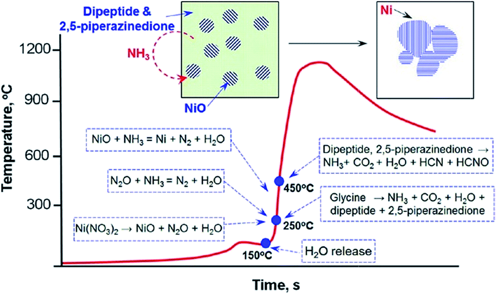 | ||
| Fig. 2 A schematic illustration showing the mechanism of Ni formation during self-sustained combustion reactions of nickel nitrate–glycine gels.74 Adopted from ref. 74, Copyright 2013, with permission from American Chemical Society. | ||
| Metals or alloys | Fuel | Other starting reactants | Fuel to oxidizer molar ratio | Atmosphere | Solvent | pH | Heating temperature/°C | Pre-dried temperature/°C | Ref. |
|---|---|---|---|---|---|---|---|---|---|
| a \ means without treatment.b — means that it was not described in the reference. | |||||||||
| Ni, Cu, and Ni–Cu | N-Tertiarybutoxy-carbonylpiperazine | Hydrated metal nitrates | 1.0 | Air | Water | \a | 350 | \a | 68 |
| Ni | Glycine | Ni(NO3)2·6H2O | 2.44 | Air | Water | \a | Microwave | \a | 69 |
| Ni, Cu, Co, Ni–Cu, and Ni–Co | Glycine | Hydrated metal nitrates | 1.4 for Ni, 2.8 for Cu, and 1.7 for Ni0.9Cu0.1 | Air | Water | \a | —b | \a | 70 |
| Co, Ni, Cu, Ag, Bi, and Ni–Co | Citric acid | Hydrated metal nitrates | 0.8–1.2 for Ni | N2 | Water | 7 | 300 | 95 | 71 |
| Ni | Glycine | Ni(NO3)2·6H2O | 1.4 | Air | Water | \a | —b | —b | 72 |
| Cu and Ni–Cu | Glycine | Hydrated metal nitrates | 3.3 for Cu and 1.9 for Cu–Ni | Air | Water | \a | —b | —b | 73 |
| Fe | Citric acid | Fe(NO3)3·9H2O | 1.25 | N2 | Water + ethanol | 6 | 300, 400, 500, 600, 700 | 95 | 75 |
| Ni–Co | Citric acid | Hydrated metal nitrates | 1.0 | N2 | Water + ethanol | 7 | 300, 400, 500, 600, 700 | 90 | 76 |
| Cu, Ag, and Ni | Glycine | Hydrated metal nitrates | 2.0 for Ni | Air | Water | \a | 250 | \a | 77 |
| Ni–Cu–Fe | Glycine | Metal nitrates | 1.9 | Air | Water | \a | —b | —b | 78 |
4. Morphology control in SCS
Controlling nuclei formation and the subsequent crystal growth is crucial for the synthesis of high-quality crystals with certain morphologies. The rapid combustion reaction and less controllable combustion process make it difficult to control the morphology of products in SCS. The typical morphology of products by SCS is agglomerations of irregular nanoparticles.4.1 Products with regular shapes
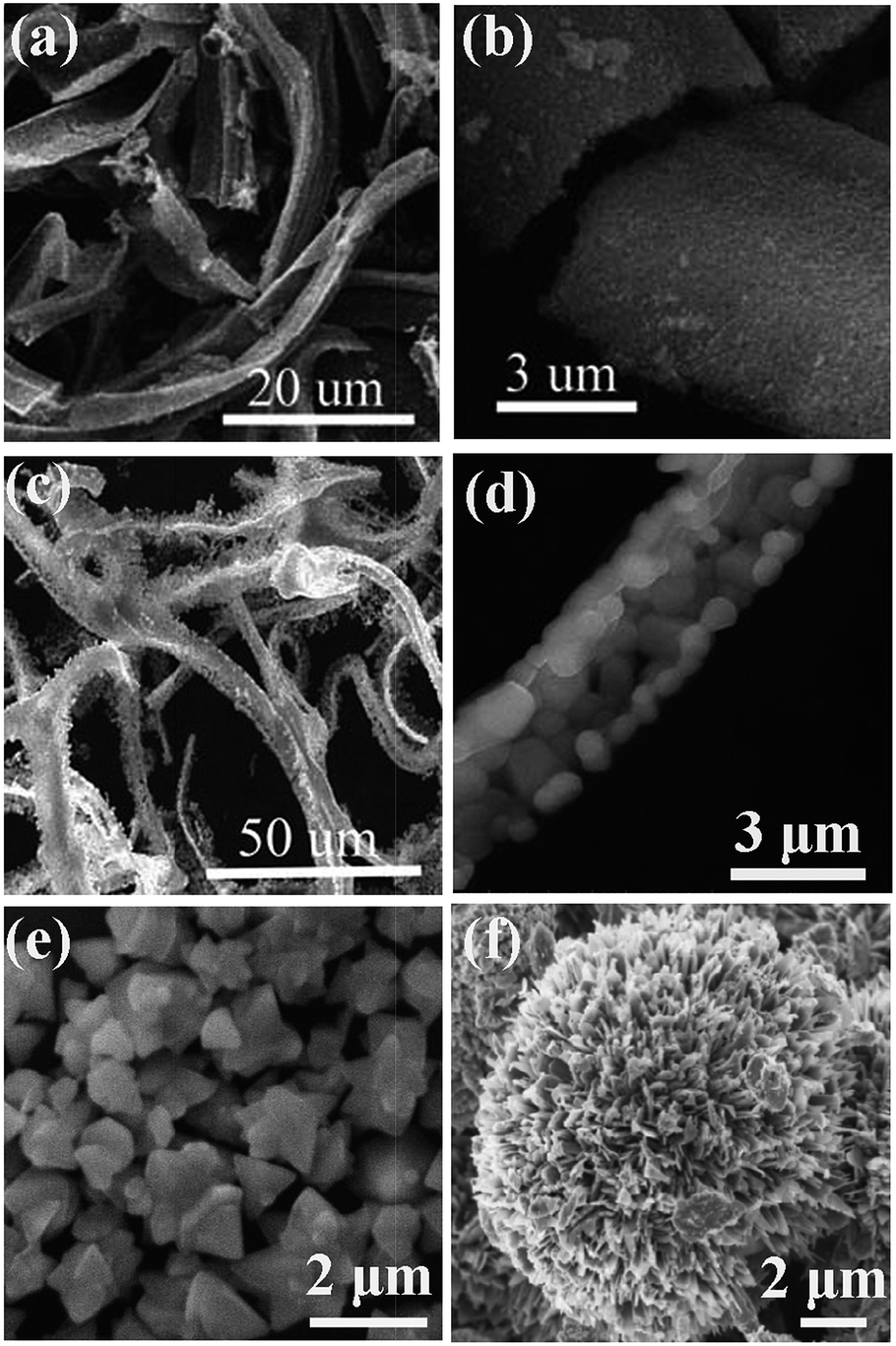
Introducing appropriate templates in SCS results in special nanostructures. For example, hydroxylapatite nanotubes have been obtained by introducing a porous anodic aluminum oxide (AAO) template in SCS.79 After the removal of the AAO template, uniform hydroxylapatite nanotubes with a fiber-brush like shape were obtained, as shown in Fig. 3a–c. The length and diameter of the nanotubes is ca. 60 μm and 100 nm, respectively. The TEM image (Fig. 3c) clearly shows the hollow structure. Just like other template-assisted synthesis methods, the preparation and removal of templates make the synthesis procedure complex and expensive.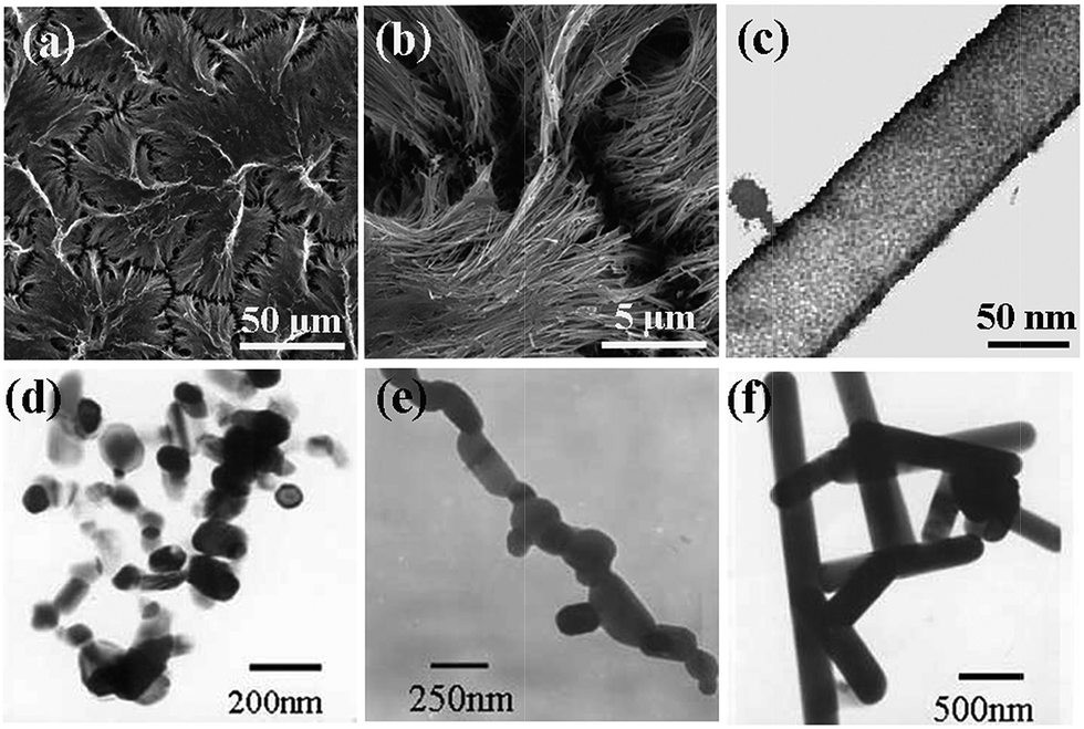 | ||
| Fig. 3 SEM (a, b) and TEM (c) images of hydroxyapatite nanotubes.79 TEM images of CaIn2O4: (d) as-combusted, (e) post-annealed at 1373 K for 2 h and (f) post-annealed at 1373 K for 12 h.80 (a–c) adopted from ref. 79, Copyright 2008, with permission from Elsevier. (d–f) adopted from ref. 80, Copyright 2009, with permission from Springer. | ||
Interestingly, one-dimensional nanostructures can sometimes be obtained by annealing the preformed nanoparticles derived form SCS.80–82 For example, Ding et al. obtained CaIn2O4 nanorods (Fig. 3f) by SCS combined with a high-temperature post-annealing.80 Firstly, CaIn2O4 nanoparticles were formed by SCS (Fig. 3d). Then, the as-combusted CaIn2O4 nanoparticles self-assembled into nanocapsules and subsequently formed the regular rods (Fig. 3e and f). The formation of rods was believed to be related to the asymmetric crystal structure of CaIn2O4 and the instantaneous high temperature involved in the combustion.80 V2O5 rods were also synthesized by SCS combined with a subsequent annealing at 550 °C for 24 h.81 Chen et al. also obtained Sn1−xRExO2−x/2 (RE = Y, La, Gd and Nd) nanorods by annealing the as-synthesized products from a microwave-induced KCl-assisted SCS.82 The diameter and length of the nanorods is 8–12 nm and 100–200 nm, respectively. The preformed nanoparticles by the KCl-assisted SCS transfer to nanorods in the molten salt during annealing.82
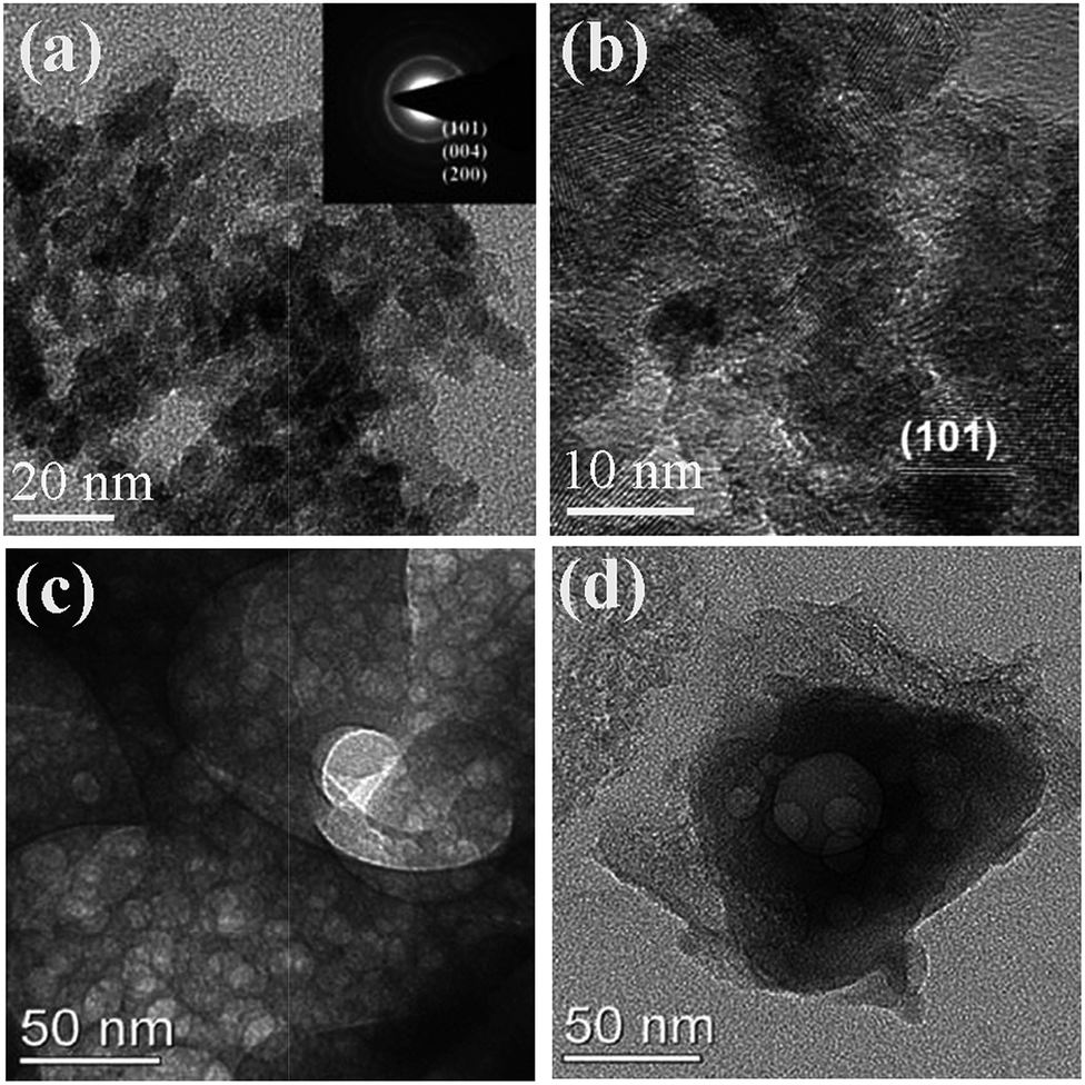
More interestingly, calcium phosphate nanowhiskers were directly prepared by a microwave-assisted auto ignition molten salt synthesis without the subsequent annealing.83 NaNO3 was used as fluxing agent and urea served as the fuel for combustion. The combustion process raises the extent of superheating in the molten-salt bath. Embryonic particles of calcium phosphates are formed through the nucleation and growth procedure. Calcium phosphate nanowhisker growth occurs by a sequential “dissolution–crystallization–whisker growth” process as the molten ionic bath cools down.83 Tao et al. achieved single-crystalline Al4B2O9 (Fig. 4a and b) and Al18B4O33 nanowires (Fig. 4c and d) by the one-step high-temperature calcination at 900 °C and 1050 °C, respectively, in which the combustion were maintained for ca. 6 min and final products were obtain after 2 h annealing.84 The cross-sectional observation reveals that the Al4B2O9 nanowires, which grew along the [100] direction, exhibited four large facets with lower surface energy and four small facets with high surface energy (Fig. 4b). For the Al18B4O33 nanowires, which grew along the [001] direction, the small facets with high surface area disappeared, resulting in a nearly square cross section (Fig. 4d). The anisotropical growth of both nanowires was believed to result from the requirement to minimize the surface energy for a free particle. The single crystalline nature for the nanowires with high purity seems to be the key to achieve the nanowires during the SCS procedure.
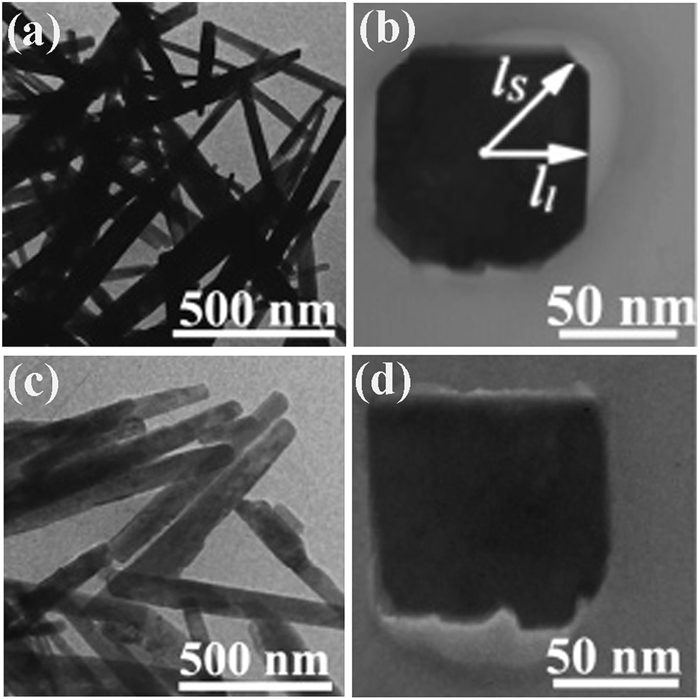 | ||
| Fig. 4 TEM images of (a and b) Al4B2O9 nanowires synthesized at 900 °C for 2 h and (c and d) Al18B4O33 nanowires synthesized at 1050 °C for 2 h.84 Adopted from ref. 84, Copyright 2007, with permission from American Chemical Society. | ||
Cheng et al. used SCS followed by a subsequent high-temperature calcination to synthesize Eu3+ incorporated ZnO belts85 (Fig. 5a and b) and SrAlxOy![[thin space (1/6-em)]](https://www.rsc.org/images/entities/char_2009.gif) :Eu2+, Dy3+ belts (Fig.5c and d).86 The introduction of N(CH2CH2OH)3 (triethanolamine, TEA) is believed to be the key to achieve the final specific morphology, because it is a multifunctional reagent serving simultaneously as a chelating agent to form metal–TEA complexes, a surfactant to control the shape of precursors, and also a fuel that is capable of reducing the reaction rate of the combustion synthesis.85,86 Mapa et al. synthesized N doped ZnO micrometer-sized triangular particles (Fig. 5e) by a combustion reaction between urea and zinc nitrate with a molar ratio of ca. 1.87 The size is relatively less uniform and is large in micro-scale rather than in nano-scale. The authors argued that, when the urea/Zn(NO3)2 molar ratio increased to beyond 3, an increasing exothermicity was achieved for the combustion reaction. As a result, no specific morphology can be observed for the resultant particles.87 The triangular particles are believed to result from the stress-free and well-grown crystals, which is expected from slow crystallization. The exact mechanism for the formation of the triangular-shaped particles by SCS, which is indeed a rapid preparation method, is therefore surprising; however, Mapa's study suggests that, for polycrystalline oxides, a moderate combustion favors the formation of particles with specific morphologies.
:Eu2+, Dy3+ belts (Fig.5c and d).86 The introduction of N(CH2CH2OH)3 (triethanolamine, TEA) is believed to be the key to achieve the final specific morphology, because it is a multifunctional reagent serving simultaneously as a chelating agent to form metal–TEA complexes, a surfactant to control the shape of precursors, and also a fuel that is capable of reducing the reaction rate of the combustion synthesis.85,86 Mapa et al. synthesized N doped ZnO micrometer-sized triangular particles (Fig. 5e) by a combustion reaction between urea and zinc nitrate with a molar ratio of ca. 1.87 The size is relatively less uniform and is large in micro-scale rather than in nano-scale. The authors argued that, when the urea/Zn(NO3)2 molar ratio increased to beyond 3, an increasing exothermicity was achieved for the combustion reaction. As a result, no specific morphology can be observed for the resultant particles.87 The triangular particles are believed to result from the stress-free and well-grown crystals, which is expected from slow crystallization. The exact mechanism for the formation of the triangular-shaped particles by SCS, which is indeed a rapid preparation method, is therefore surprising; however, Mapa's study suggests that, for polycrystalline oxides, a moderate combustion favors the formation of particles with specific morphologies.
 | ||
| Fig. 5 SEM images of the ZnO post-annealing at 600 °C (a and b),85 SrAlxOy post-annealing at 1300 °C (c and d),86 triangular ZnO (e),87 and CuO nanoflowers (f).88 (e) Adopted from ref. 87, Copyright 2009, with permission from American Chemical Society. (f) Adopted from ref. 88, Copyright 2013, with permission from Elsevier. | ||
Recently, copper oxide (CuO) nanoflowers, as shown in Fig. 5f, were prepared by SCS, where glycine was used as a fuel.88 The CuO nanoflowers contain well-crystallized nanopetals/sheets. The flower-like structure was believed to come into being through the local sintering of the preformed nanoparticles during the high temperature combustion.
Although some progresses have been made, most of regular morphologies reported to date are in micro-scale or need a subsequent annealing. For the AAO-assisted SCS to obtain one-dimensional (1D) nanostructures, the penetration of the precursor into the templates is the key point.79 For crystals with asymmetric structures, the subsequent annealing is capable of inducing self-assembly of nanoparticles preformed during the SCS procedure, especially for those in the molten salts, to achieve 1D nanostructures.80–82 It still remains a challenge to directly obtain regular and uniform nanostructures by SCS. The exact mechanism for the formation of the unique nanostructure during SCS is still unclear because of the rapid and unknown combustion process. For asymmetric crystals with high purity, it is possible to achieve directly 1D structures because of the driving force for minimizing the total surface energy.84 For 3D structures of flower-like particles, an appropriate combustion environment favoring the local sintering of the preformed nanoparticles is of importance.88 Further work is needed to clarify the exact formation mechanism of the various morphologies. We believe a deep understanding on the nucleation and crystal growth procedure characteristic of SCS would help clarifying the formation of the specific nanostructure during SCS. In situ electron microscopic observation would be also helpful to understand the mechanism of morphology evolution during SCS.
4.2 Porous materials
Porous materials have promising applications in the various fields of gas sensors, catalysis, separation, energy storage and energy conversion.89–91 Most methods for synthesis of porous materials demand the assistance of templates: hard templates (mesoporous silica, silica sphere, or polystyrene sphere) and soft templates (surfactants or block copolymers).92,93 Because of the advantages of rapid and energy efficient, it is interesting to adopt SCS to synthesize porous materials, which is simple, template-free and low cost. Sometimes porous structures can be obtained as a result of the gas evolution during the combustion reaction; however, the pores are usually inhomogeneous and most of pore size is in tens of micrometers. It is of importance to obtain relatively homogeneous porous materials with pore sizes ranging from nanometers to several micrometers, which is favorable for gas or liquid diffusion and provides a relatively large surface area.Phase and surface area of products in SCS are greatly affected by fuels and fuel/oxidizer ratio. Anatase TiO2 with high specific surface area and disordered mesopores (Fig. 6a and b) was successfully synthesized through SCS by using many kinds of fuels, such as glycine,94–97 urea,98–101 hexamethylenetetramine,95 and oxalyldihydrazide.95 Zhang et al. obtained porous Li3V2(PO4)3/C (as shown in Fig. 6c and d) with a surface area of 25.7 m2 g−1 by annealing sucrose and combustion-driven amorphous precursor at 800 °C for 8 h in a N2 atmosphere, and this material exhibited excellent electrochemical properties.61 Mesoporous MgO with a surface area of 107 m2 g−1 was obtained by SCS, which exhibited excellent fluoride removal capacity.102 Mesoporous alumina with high surface area and narrow pore size distribution was also prepared by SCS in a fuel (urea)-lean condition. The surface area decreased with increasing amounts of urea.103 However, the as-synthesized alumina was amorphous and the surface area greatly decreased upon the subsequent crystallization procedure.103 It is still difficult to extend this procedure for synthesis of other porous oxides with relatively uniform pores because of the unknown and uncontrollable combustion process.16
 | ||
| Fig. 6 (a) TEM image and (b) HRTEM image of TiO2 with wormhole mesopores.98 (c and d) TEM images of porous Li3V2(PO4)3/C.61 (c and d) Adopted from ref. 61, Copyright 2012, with permission from Elsevier. | ||
Chen et al. is the first to introduce salts in SCS, which greatly increases the surface area of products in SCS.104 The role of salts is believed to be two folds: decreasing the reaction temperature because the salt additives absorb reaction heat; salt precipitated in situ coats the newly formed nanoparticles, preventing them from sintering and agglomerating.104–107 The salts are inexpensive and can be easily removed from the products by water washing. For the stoichiometric combustion reaction between nickel nitrate hexahydrate and citric acid, NaF is found to be more effective than NaCl for improving the surface area.108 More interestingly, the additive of appropriate amounts of NaF alters the combustion mode, which results in the appearance of the so-called eruption combustion. In the eruption combustion process, lots of powders were lifted off and naturally fall down around the container, leaving highly fluffy products with a quite big volume, as shown in Fig. 7a. This phenomenon is very similar to a volcano eruption in nature (Fig. 7b). The eruption combustion in nickel nitrate–citric acid system resulted in smaller particles, improved dispersity, and remarkably increased specific surface area, as shown in Fig. 7c and d.108 Moreover, it was shown that introduction of high surface area carriers in SCS also helps to obtain high surface area oxide-based supported catalysts.109
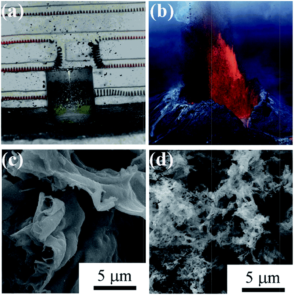 | ||
| Fig. 7 Optical photographs of eruption combustion process (a) and volcanic eruption in nature (b). The optical photograph showing a natural volcanic eruption is from the Internet. SEM images of Ni/NiO powders derived with conventional combustion (c) and eruption combustion (d).108 Adopted from ref. 108, Copyright 2011, with permission from American Chemical Society. | ||
Fuel-rich conditions in SCS usually result in residual organics in the products. Carefully selecting fuels and adopting a high fuel/oxidizer ratio can obtain an organic-rich and amorphous precursor, which further decomposes to form porous metal oxide by the subsequent calcination because of gas evolutions. By using this method, homogeneously macroporous ZnO can be achieved, as shown in Fig. 8a and b.110 The synthesis route can also be extended to the preparation of other porous oxides. For example, porous Co3O4 (Fig. 8c and d) can be also obtained by this method.111 The decomposition temperature of the Co-based precursor is much lower than that of the Zn-based precursor.110,111 The low decomposition temperature of the Co-based precursor is beneficial for the formation of the mesoporous Co3O4 network (Fig. 8c). Increasing the calcination temperature results in a larger particle size and larger pore size of the porous Co3O4, as shown in Fig. 8d, due to the enhanced grain growth.111
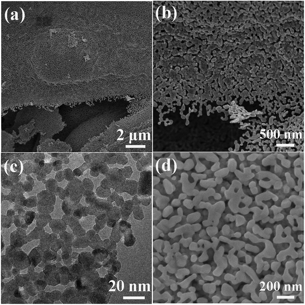 | ||
| Fig. 8 (a and b) SEM images of porous ZnO network.110 (c) TEM image of mesoporous Co3O4 calcined at 355 °C.111 (d) SEM image of macroporous Co3O4 calcined at 550 °C.111 (a and b) Adopted from ref. 110, Copyright 2012, with permission from AIP Publishing. | ||
Hydrazine has a high energy N–N bond and lone electron pairs, which can coordinate with metal ions to form metal complexes.15 Such metal hydrazine complexes can serve as precursors to be decomposed to corresponding oxide materials under low temperatures.112–114 The energetic complexes usually decompose in an exothermal way along with combustion at low temperatures. Moreover, the raw materials for the complexes are water-soluble. Thus, the synthesis route starting from metal hydrazine complexes is very similar to the SCS procedure and can be classified as SCS. Recently we used metal nitrate, metal acetate, hydrazine hydrate, and glycine to synthesize homogeneous macroporous NiO/Ni115 and porous ZnO.116 The morphology of macroporous NiO/Ni can be changed by adjusting the complex composition. For example, macroporous NiO/Ni with three-dimensional (3D) and two-dimensional (2D) architectures can be achieved, as shown in Fig. 9a–d. The content of NiO in the macroporous NiO/Ni can be controlled by a subsequent calcination, with the macroporous structure preserved.117 The obtained ZnO exhibits a coral-like macro-/mesoporous structure (Fig. 9e and f).116 Interestingly, this kind of metal hydrazine complexes can transform to macro-/meso-/microporous nanofoam structures under focused electron beam irradiation during TEM operation. For example, porous ZnO nanofoams with ultrathin walls (Fig. 10a–c) are obtained via focused electron beam irradiation of the zinc hydrazine complex, whose preparation process is the same to that in the ref. 116 As shown in the HRTEM image (Fig. 10c), the measured lattice spacing of 0.25 nm and 0.26 nm represents the (101) and (002) atomic plane of wurtzite ZnO, respectively. The SAED pattern (Fig. 10d) further demonstrates that the product is polycrystalline wurtzite ZnO. This difference of morphology (comparing Fig. 10a–c with Fig. 9e and f) may be attributed to the different heating rates and atmospheric pressures. The much higher heating rate of the focused electron beam and lower atmospheric pressure during TEM operation result in the formation of porous nanofoams with ultrathin walls. This one-step route to porous structures is simple and rapid; however, hydrazine is toxic, and the reaction is relatively violent and hence careful operation and safety protection are required.
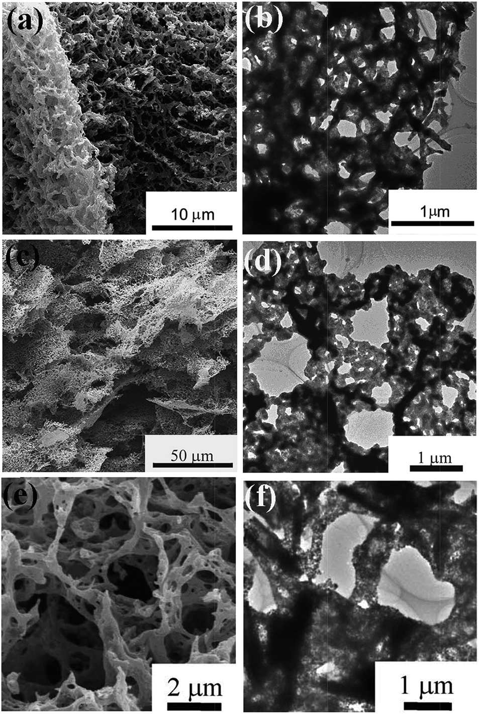 | ||
| Fig. 9 SEM image (a) and TEM image (b) of 3D macroporous NiO/Ni. SEM image (c) and TEM mage (d) of 2D macroporous NiO/Ni.115 SEM image (e) and TEM image (f) of 3D porous ZnO.116 (a–d) Adopted from ref. 115, Copyright 2013, with permission from Elsevier. | ||
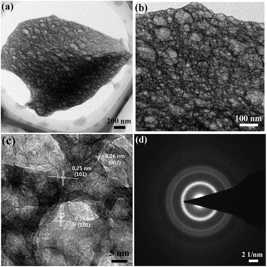 | ||
| Fig. 10 TEM images (a, b), HRTEM image (c), and SAED pattern (d) of porous ZnO nanofoams derived from focused electron beam irradiation of the zinc hydrazine complex under TEM operation. | ||
4.3 Thin films
SCS is more commonly used to produce materials in form of powders. Many precursors employed in SCS have an uncanny resemblance to corresponding compounds utilized in sol–gel routes.21 Thus, it is possible to obtain metal oxide thin films by SCS. Recently, Marks et al. adopt SCS as a new general route to fabricate diverse metal oxide thin films of In2O3, Zn–Sn–O, In–Zn–O, and ITO.51 Taking the synthesis of ZnO films for example, 297.5 mg Zn(NO3)2·6H2O and 100.1 mg urea were dissolved in 5 ml 2-methoxyethanol and aged for 72 h. Then, the films were fabricated by spin coating and annealed at the desired temperature (150–400 °C) for 30 min in air.51 Fig. 11a–c shows the SEM images of SCS-derived In2O3 thin films with controlled thickness.51 Thin films with a thickness of 30 nm or less exhibit smooth surfaces and negligible porosity; on the contrary, those with a thickness over 70 nm exhibit voids and evidence of porosity because of gas release during SCS. Growth of thicker and denser films thus demands multiple depositions.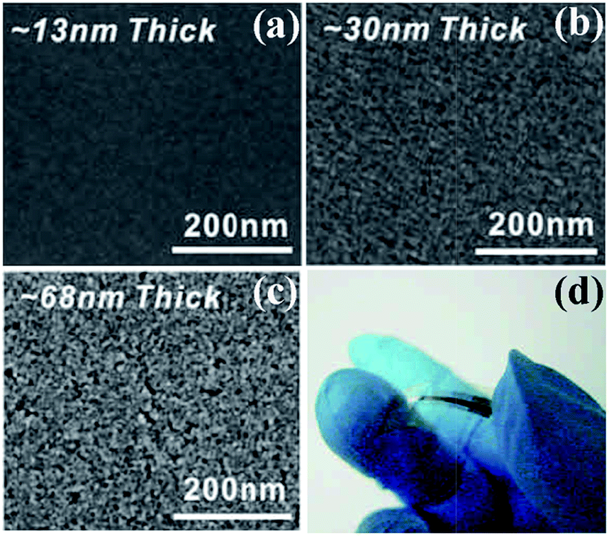 | ||
| Fig. 11 (a–c) SEM images of In2O3 films on n++ Si with controlled thickness. (d) Optical image of a flexible combustion-processed In2O3 device.51 Adopted from ref. 51, Copyright 2011, with permission from Macmillan Publishers Ltd. | ||
The driving force of oxide lattice formations in SCS is from the internal chemical energy; therefore, the required temperature is just for reaction initiation rather than continuous energy input. These unique advantages endow SCS the ability to grow metal oxide films at temperatures as low as 200 °C.51 It is thus convenient to achieve optically transparent transistors on flexible plastic substrates (Fig. 11d).51,52 In a word, SCS enables the fabrication of low-cost and high-performance electronics at low temperatures.51–55
5. Conclusions and perspectives
Solution combustion synthesis has been adopted worldwide to synthesize numerous nanomaterials, especially simple and complex oxides, because of its simplicity, energy- and time-effectiveness, and low cost. The recent progress on controlled synthesis in SCS is described in detail in this review. It is a big challenge to obtain products with well defined phases and morphologies by SCS, which is partially attributed to the rapid and uncontrollable combustion procedure.Besides the various metal oxides, it is now possible to synthesize metal sulfides, metals, and alloys, through careful selections of fuel and appropriate fuel/oxidant ratio. The metals or alloys are believed to result from the further reduction of the pre-formed corresponding metal oxides by the reducing atmosphere, which comes from either the excessive reducing fuel or the gas evolution during the combustion in fuel-rich conditions. The synthesis of other species, such as metal nitrides, metal carbides, and metal borides for a wider application still remains a challenge.
Oxides with regular morphologies of belts, triangles, tubes, wires, and rods can be synthesized by SCS, in the presence of certain templates, or through a self-assembly procedure. Utilizing the driving force for minimizing the total surface energy, SCS is capable of fabricating directly 1D structures when the target products are of asymmetric crystals. To achieve 3D structures of flower-like particles in one-step by SCS, an appropriate combustion environment should be maintained to favor the local sintering of the preformed nanoparticles to the resultants with specific morphologies.
More commonly, products in SCS are aggregates of nanoparticles, with relatively low specific surface area. The salt-assisted SCS favors the synthesis of oxides with small particles and thus high specific surface area. The additive of NaF in certain SCS system induced a novel eruption combustion mode, which further improves the dispersion and specific surface area of the produced oxides. Organic-rich precursor can be obtained by carefully selecting fuels and adopting a high fuel/oxidizer ratio, which further decomposes to form porous metal oxide by the subsequent calcination because of gas evolutions. Decomposition of metal hydrazine complexes is capable of producing oxides with high porosity. By adjusting the complex intensity, the architecture of the products can also be controlled. SCS is also developed to fabricate metal oxide thin films at low temperatures, enabling the fabrication of low-cost and high-performance electronics on flexible plastic substrates.
With the efforts of researchers worldwide, remarkable progresses have been made towards a more controllable SCS. However, the exact mechanism of SCS still remains unclear and it is a big challenge to achieve SCS products with well-defined phase structure and pre-designed morphology. Further work is needed to clarify the phase and microstructure evolution in the combustion process and to effectively control the combustion process.
Acknowledgements
This work is supported by the Natural Science Foundation of Zhejiang Province (Project no. LY13E020001). Dr Wen thanks a scholarship award for Excellent Doctoral Student granted by Ministry of Education, China for the financial support.Notes and references
- M. N. Rahaman, Ceramic Processing and Sintering, Marcel & Dekker, New York, 2nd edn, 1995 Search PubMed.
- Chemical Processing of Ceramics, ed. B. Lee and S. Komarneni, Taylor and Francis, New York, 2005 Search PubMed.
- A. S. Mukasyan, P. Epstein and P. Dinka, Proc. Combust. Inst., 2007, 31, 1789 CrossRef PubMed.
- S. T. Aruna and A. S. Mukasyan, Curr. Opin. Solid State Mater. Sci., 2008, 12, 44 CrossRef CAS PubMed.
- H. Birol, C. R. Rambo, M. Guiotoku and D. Hotza, RSC Adv., 2013, 3, 2873 RSC.
- K. C. Patil, S. T. Aruna and T. Mimani, Curr. Opin. Solid State Mater. Sci., 2002, 6, 507 CrossRef CAS.
- R. Rosa, P. Veronesi and C. Leonelli, Chem. Eng. Process., 2013, 71, 2 CrossRef CAS PubMed.
- J. J. Moore and H. J. Feng, Prog. Mater. Sci., 1995, 39, 243 CrossRef CAS.
- K. C. Patil, S. T. Aruna and S. Ekambaram, Curr. Opin. Solid State Mater. Sci., 1997, 2, 158 CrossRef CAS.
- Z. Du, H. Fu, H. Fu and Q. Xiao, Mater. Lett., 2005, 59, 1583 Search PubMed.
- F. Bernard and E. Gaffet, Int. J. Self-Propag. High-Temp. Synth., 2001, 10, 109 CAS.
- L. Stobierski, Z. Wegrzyn, J. Lis and M. Buck, Int. J. Self-Propag. High-Temp. Synth., 2001, 10, 217 CAS.
- I. P. Borovinskaya, T. I. Ignat'eva, V. I. Vershinnikov, G. G. Khurtina and N. V. Sachkova, Inorg. Mater., 2003, 39, 588 CrossRef CAS.
- J. J. Kingsley and K. C. Patil, Mater. Lett., 1988, 6, 427 CrossRef CAS.
- K. C. Patil, M. S. Hegde, R. Yanu and S. T. Atuna, Chemistry of nanocrystalline oxide materials: combustion synthesis, properties and applications, World Scientific, Singapore, 2008 Search PubMed.
- Combustion synthesis: novel routes to novel materials, ed. M. Lackner, Betham science publishers, 2010 Search PubMed.
- J. Lin, M. Yu, C. Lin and X. Liu, J. Phys. Chem. C, 2007, 111, 5835 CAS.
- S. R. Jain, K. C. Adiga and V. R. Pai Verneker, Combust. Flame, 1981, 40, 71 CrossRef CAS.
- H. Q. Jiang, H. Endo, H. Natori, M. Nagai and K. Kobayashi, J. Eur. Ceram. Soc., 2008, 28, 2955 CrossRef CAS PubMed.
- W. Wen, J. M. Wu and Y. D. Wang, Sens. Actuators, B, 2013, 184, 78 CrossRef CAS PubMed.
- K. Rajeshwar and N. R. de Tacconi, Chem. Soc. Rev., 2009, 38, 1984 RSC.
- M. S. Hegde, G. Madras and K. C. Patil, Acc. Chem. Res., 2009, 42, 704 CrossRef CAS PubMed.
- K. Nagaveni, M. S. Hegde, N. Ravishankar, G. N. Subbanna and G. Madras, Langmuir, 2004, 20, 2900 CrossRef CAS.
- K. R. Priolkar, P. Bera, P. R. Sarode, M. S. Hegde, S. Emura, R. Kumashiro and N. P. Lalla, Chem. Mater., 2002, 14, 2120 CrossRef CAS.
- X. Guo, D. Mao, G. Lu, S. Wang and G. Wu, J. Catal., 2010, 271, 178 CrossRef CAS PubMed.
- J. M. Wu and W. Wen, Environ. Sci. Technol., 2010, 44, 9123 CrossRef CAS PubMed.
- S. Pany, K. M. Parida and B. Naik, RSC Adv., 2013, 3, 4976 RSC.
- W. Morales, M. Cason, O. Aina, N. R. de Tacconi and K. Rajeshwar, J. Am. Chem. Soc., 2008, 130, 6318 CrossRef CAS PubMed.
- S. L. Gonzalez-Cortes and F. E. Imbert, Appl. Catal., A, 2013, 452, 117 CrossRef CAS PubMed.
- A. Zhao, W. Ying, H. Zhang, H. Ma and D. Fang, Catal. Commun., 2012, 17, 34 CrossRef CAS PubMed.
- S. Ekambarama, K. C. Patil and M. Maazac, J. Alloys Compd., 2005, 393, 81 CrossRef PubMed.
- Z. Qiu, Y. Zhou, M. Lu, A. Zhang and Q. Ma, Acta Mater., 2007, 55, 2615 CrossRef CAS PubMed.
- V. Singh, S. Watanabe, T. K. G. Rao, K. Al-Shamery, M. Haase and Y. D. Jho, J. Lumin., 2012, 132, 2036 CrossRef CAS PubMed.
- Z. Qiu, Y. Zhou, M. Lü, A. Zhang and Q. Ma, Solid State Sci., 2008, 10, 629 CrossRef CAS PubMed.
- S. S. Yao, L. H. Xue and Y. W. Yan, J. Alloys Compd., 2011, 509, 1870 CrossRef CAS PubMed.
- S. S. Yao, L. H. Xue, Y. W. Yan and M. F. Yan, J. Am. Ceram. Soc., 2011, 94, 1477 CrossRef CAS PubMed.
- H. Mohebbi, T. Ebadzadeh and F. A. Hesari, J. Power Sources, 2008, 178, 64 CrossRef CAS PubMed.
- M. A. Raza, I. Z. Rahman and S. Beloshapkin, J. Alloys Compd., 2009, 485, 593 CrossRef CAS PubMed.
- B. S. Prakash, V. K. W. Grips and S. T. Aruna, J. Power Sources, 2012, 214, 358 CrossRef PubMed.
- S. L. Chung and C. M. Wang, J. Mater. Sci. Technol., 2012, 28, 713 CAS.
- S. A. Kelkar, P. A. Shaikh, P. Pachfule and S. B. Ogale, Energy Environ. Sci., 2012, 5, 5681 CAS.
- K. Sivaranjani, S. Agarkar, S. B. Ogale and C. S. Gopinath, J. Phys. Chem. C, 2012, 116, 2581 CAS.
- P. Manikandan, M. V. Ananth, T. P. Kumar, M. Raju, P. Periasamy and K. Manimaran, J. Power Sources, 2011, 196, 10148 CrossRef CAS PubMed.
- W. Wen, J. M. Wu and J. P. Tu, J. Alloys Compd., 2012, 513, 592 CrossRef CAS PubMed.
- G. T. K. Fey, Y. D. Cho and T. P. Kumar, Mater. Chem. Phys., 2006, 99, 451 CrossRef CAS PubMed.
- A. S. Prakash, P. Manikandan, K. Ramesha, M. Sathiya, J. M. Tarascon and A. K. Shukla, Chem. Mater., 2010, 22, 2857 CrossRef CAS.
- A. Huczko, M. Kurcz, P. Baranowski, M. Bystrzejewski, A. Bhattarai, S. Dyjak, R. Bhatta, B. Pokhrel and B. P. Kafle, Phys. Status Solidi B, 2013, 250, 2702 CrossRef CAS.
- K. Suresh, N. R. S. Kumar and K. C. Patil, Adv. Mater., 1991, 3, 148 CrossRef CAS.
- K. Laishram, R. Mann and N. Malhan, Ceram. Int., 2011, 37, 3743 CrossRef CAS PubMed.
- M. B. Kakadea, S. Ramanathana and P. V. Ravindran, J. Alloys Compd., 2003, 350, 123 CrossRef.
- M. G. Kim, M. G. Kanatzidis, A. Facchetti and T. J. Marks, Nat. Mater., 2011, 10, 382 CrossRef CAS PubMed.
- Y. S. Rim, H. S. Lim and H. J. Kim, ACS Appl. Mater. Interfaces, 2013, 5, 3565 CAS.
- J. W. Hennek, M. G. Kim, M. G. Kanatzidis, A. Facchetti and T. J. Marks, J. Am. Chem. Soc., 2012, 134, 9593 CrossRef CAS PubMed.
- M. G. Kim, J. W. Hennek, H. S. Kim, M. G. Kanatzidis, A. Facchetti and T. J. Marks, J. Am. Chem. Soc., 2012, 134, 11583 CrossRef CAS PubMed.
- D. Sanchez-Rodriguez, J. Farjas, P. Roura, S. Ricart, N. Mestres, X. Obradors and T. Puig, J. Phys. Chem. C, 2013, 117, 20133 CAS.
- A. Cüneyt Tas, J. Eur. Ceram. Soc., 2000, 20, 2389 CrossRef.
- S. Gallini, J. R. Jurado and M. T. Colomer, Chem. Mater., 2005, 17, 4154 CrossRef CAS.
- M. T. Colomer, S. Gallini and J. R. Jurado, J. Eur. Ceram. Soc., 2007, 27, 4237 CrossRef CAS PubMed.
- I. M. Nagpure, K. N. Shinde, V. Kumar, O. M. Ntwaeaborwa, S. J. Dhoble and H. C. Swart, J. Alloys Compd., 2010, 492, 384 CrossRef CAS PubMed.
- B. Zhao, X. Yu, R. Cai, R. Ran, H. Wang and Z. Shao, J. Mater. Chem., 2012, 22, 2900 RSC.
- L. Zhang, H. Xiang, Z. Li and H. Wang, J. Power Sources, 2012, 203, 121 CrossRef CAS PubMed.
- M. Pardha Saradhi and U. V. Varadaraju, Chem. Mater., 2006, 18, 5267 CrossRef.
- M. Dahbi, S. Urbonaite and T. Gustafsson, J. Power Sources, 2012, 205, 456 CrossRef CAS PubMed.
- D. Wang, B. A. Doull, L. C. Oliveira and E. G. Yukihara, RSC Adv., 2013, 3, 26127 RSC.
- R. K. Tukhtaev, V. V. Boldyrev, A. I. Gavrilov, S. V. Larionov, L. I. Myachina and Z. A. Savel'eva, Inorg. Mater., 2002, 38, 985 CrossRef CAS.
- S. Arora and S. S. Manoharan, J. Phys. Chem. Solids, 2007, 68, 1897 CrossRef CAS PubMed.
- R. Amutha, M. Muruganandham, G. J. Lee and J. J. Wu, J. Nanosci. Nanotechnol., 2011, 11, 7940 CrossRef CAS PubMed.
- G. R. Rao, B. G. Mishra and H. R. Sahu, Mater. Lett., 2004, 58, 3523 CrossRef CAS PubMed.
- C. H. Jung, S. Jalota and S. B. Bhaduri, Mater. Lett., 2005, 59, 2426 CrossRef CAS PubMed.
- P. Erri, J. Nader and A. Varma, Adv. Mater., 2008, 20, 1243 CrossRef CAS.
- Y. Jiang, S. Yang, Z. Hua and H. Huang, Angew. Chem., Int. Ed., 2009, 48, 8529 CrossRef CAS PubMed.
- A. Kumar, E. E. Wolf and A. S. Mukasyan, AIChE J., 2010, 57, 2207 CrossRef.
- A. Kumar, E. E. Wolf and A. S. Mukasyan, AIChE J., 2011, 12, 3473 CrossRef.
- K. V. Manukyan, A. Cross, S. Roslyakov, S. Rouvimov, A. S. Rogachev, E. E. Wolf and A. S. Mukasyan, J. Phys. Chem. C, 2013, 117, 24417 CAS.
- Z. Hua, Y. Deng, K. Li and S. Yang, Nanoscale Res. Lett., 2012, 7, 129 CrossRef PubMed.
- Z. H. Hua, Z. W. Cao, Y. Deng, Y. W. Liang and S. G. Yang, Mater. Chem. Phys., 2011, 126, 542 CrossRef CAS PubMed.
- P. Gómez-Romero, J. Frailec and B. Ballesteros, RSC Adv., 2013, 3, 2351 RSC.
- A. Kumara, J. T. Miller, A. S. Mukasyan and E. E. Wolf, Appl. Catal., A, 2013, 467, 593 CrossRef PubMed.
- Y. Yuan, C. S. Liu, Y. Zhang and X. Q. Shan, Mater. Chem. Phys., 2008, 112, 275 CrossRef CAS PubMed.
- J. Ding, S. Sun, J. Bao, Z. Luo and C. Gao, Catal. Lett., 2009, 130, 147 CrossRef CAS.
- P. A. Deshpande and G. Madras, AIChE J., 2011, 57, 2215 CrossRef CAS.
- W. Chen, M. Liu, Y. Lin, Y. Liu, L. Yu, T. Li and J. Hong, Ceram. Int., 2013, 39, 7545 CrossRef CAS PubMed.
- S. Jalota, A. C. Tas and S. B. Bhaduri, J. Mater. Res., 2004, 19, 1876 CrossRef CAS.
- X. Y. Tao, X. N. Wang and X. D. Li, Nano Lett., 2007, 7, 3172 CrossRef CAS PubMed.
- B. C. Cheng, Z. D. Zhang, H. J. Liu, Z. H. Han, Y. H. Xiao and S. J. Lei, J. Mater. Chem., 2010, 20, 7821 RSC.
- B. C. Cheng, Z. D. Zhang, Z. H. Han, Y. H. Xiao and S. J. Lei, CrystEngComm, 2011, 13, 3545 RSC.
- M. Mapa and C. S. Gopinath, Chem. Mater., 2009, 21, 351 CrossRef CAS.
- M. Umadevi and A. J. Christy, Spectrochim. Acta, Part A, 2013, 109, 133 CrossRef CAS PubMed.
- V. Valtchev and L. Tosheva, Chem. Rev., 2013, 113, 6734 CrossRef CAS PubMed.
- N. D. Petkovich and A. Stein, Chem. Soc. Rev., 2013, 42, 3721 RSC.
- A. Stein, B. E. Wilson and S. G. Rudisill, Chem. Soc. Rev., 2013, 42, 2763 RSC.
- X. Chen, J. Ye, S. Ouyang, T. Kako, Z. Li and Z. Zou, ACS Nano, 2011, 5, 4310 CrossRef CAS PubMed.
- J. M. Wu, M. Antonietti, S. Gross, M. Bauer and B. M. Smarsly, ChemPhysChem, 2008, 9, 748 CrossRef CAS PubMed.
- G. Sivalingam, K. Nagaveni, M. S. Hegde and G. Madras, Appl. Catal., B, 2003, 45, 23 CrossRef CAS.
- K. Nagaveni, M. S. Hegde, N. Ravishankar, G. N. Subbanna and G. Madras, Langmuir, 2004, 20, 2900 CrossRef CAS.
- K. Nagaveni, M. S. Hegde and G. Madras, J. Phys. Chem. B, 2004, 108, 20204 CrossRef CAS.
- A. D. Mani, V. Laporte, P. Ghosal and C. Subrahmanyam, Mater. Res. Bull., 2012, 47, 2415 CrossRef PubMed.
- K. Sivaranjani and C. S. Gopinath, J. Mater. Chem., 2011, 21, 2639 RSC.
- K. Sivaranjani, S. Agarkar, S. B. Ogale and C. S. Gopinath, J. Phys. Chem. C, 2012, 116, 2581 CAS.
- S. S. Negi, K. Sivaranjani, A. P. Singh and C. S. Gopinath, Appl. Catal., A, 2013, 452, 132 CrossRef CAS PubMed.
- S. Pany, K. M. Parida and B. Naik, RSC Adv., 2013, 3, 4976 RSC.
- B. Nagappa and G. T. Chandrappa, Microporous Mesoporous Mater., 2007, 106, 212 CrossRef CAS PubMed.
- M. Pavese and S. Biamino, J. Porous Mater., 2009, 16, 59 CrossRef CAS.
- W. Chen, F. Li, J. Yu and L. Liu, Mater. Sci. Eng., B, 2006, 133, 151 CrossRef CAS PubMed.
- W. Chen, J. Hong and Y. Li, J. Alloys Compd., 2009, 484, 846 CrossRef CAS PubMed.
- X. Zhang, W. Jiang, D. Song, H. Sun, Z. Sun and F. Li, J. Alloys Compd., 2009, 475, L34 CrossRef CAS PubMed.
- Y. Tong, S. Zhao, X. Wang and L. Lu, J. Alloys Compd., 2009, 479, 764 CrossRef PubMed.
- W. Wen and J. M. Wu, ACS Appl. Mater. Interfaces, 2011, 3, 4112 CAS.
- P. Dinka and A. S. Mukasyan, J. Phys. Chem. B, 2005, 109, 21627 CrossRef CAS PubMed.
- W. Wen, J. M. Wu and Y. D. Wang, Appl. Phys. Lett., 2012, 100, 262111 CrossRef PubMed.
- W. Wen, J. M. Wu and M. H. Cao, Nanoscale, 2014, 6, 12476 RSC.
- K. C. Patil, Proc.–Indian Acad. Sci., Chem. Sci., 1986, 96, 459 CrossRef CAS.
- T. T. Srinivasan, P. Ravindranathan, L. E. Cross, R. Roy, R. E. Newnham, S. G. Sankar and K. C. Patil, J. Appl. Phys., 1988, 63, 3789 CrossRef CAS PubMed.
- J. W. Park, E. H. Chae, S. H. Kim, J. H. Lee, J. W. Kim, S. M. Yoon and J. Y. Choi, Mater. Chem. Phys., 2006, 97, 371 CrossRef CAS PubMed.
- W. Wen, J. M. Wu and M. H. Cao, Nano Energy, 2013, 2, 1383 CrossRef CAS PubMed.
- W. Wen, J. M. Wu and Y. D. Wang, RSC Adv., 2013, 3, 12052 RSC.
- W. Wen, J. M. Wu and M. H. Cao, J. Mater. Chem. A, 2013, 1, 3881 CAS.
| This journal is © The Royal Society of Chemistry 2014 |