Enhanced performance of p-type dye sensitized solar cells based on mesoporous Ni1−xMgxO ternary oxide films
Zhanfeng Huang†
a,
Xianwei Zeng†a,
Huan Wanga,
Wenjun Zhanga,
Yanmin Lia,
Mingkui Wang a,
Yi-Bing Chengab and
Wei Chen*a
aMichael Gratzel Centre for Mesoscopic Solar Cells, Wuhan National Laboratory for Optoelectronics, Huazhong University of Science and Technology, Wuhan, China. E-mail: wnlochenwei@mail.hust.edu.cn; Fax: +86 27 8779 3524; Tel: +86 27 8779 3524
bDepartment of Materials Engineering, Monash University, Melbourne, Victoria 3800, Australia
First published on 7th November 2014
Abstract
A series of Ni1−xMgxO (x = 0–0.2) oxide mesoporous films with p-type semi-conductivity prepared by surfactant directed self-assembly method have been successfully applied as photocathodes in a p-type dye sensitized solar cell (DSC) system. By gradually increasing the Mg content from 0 to 20% in the ternary oxides, the effective light harvesting efficiency increases monotonically, which is associated with the increased dye absorbing amount and improved optical transmittance, meanwhile the flat-band potential gradually increases, implying a continuous negative shift of the valance band position of the p-type semiconductors. The latter is closely related to the charge injection from dye to semiconductor and the photovoltage (Voc) of the solar cell. The overall power conversion efficiency is optimized for the Ni0.9Mg0.1O photocathode, which is significantly improved by about 85% from pure NiO. The enhanced performance is attributed to 34.4% increased photocurrent density (Jsc), 22.5% increased Voc, and 13.0% increased fill factor. These improvements can be explained by increased light harvesting, enhanced charge collection, and flat-band potential positive shift. On further increasing the Mg content in the ternary oxide to Ni0.8Mg0.2O, the valance band position is too deep and hinders efficient hole injection. Jsc of the corresponding solar cell decreases largely. This work proves that Ni0.9Mg0.1O is a superior alternative to NiO as a photocathode material in p-type DSCs.
Introduction
The research on dye sensitized p-type semiconductor solar cells (called p-DSCs) has gained increasing attention during recent years, owing to the possibility to fabricate tandem solar cells with n type semiconductor based DSCs (n-DSCs).1–13 This concept of tandem solar cells has been firstly demonstrated as a real cell by Lindquist and co-workers in 1999.14 In such a cell configuration, photoexcitation of the sensitizer in the conventional n-DSC part results in electron injection to the conduction band of the n-type semiconductors (e.g., TiO2, ZnO), while at the same time the sensitizer in the p-DSC part results in hole injection to the valance band of p-type semiconductors.15,16 The photo-oxidized or reduced dye is then regenerated by a commonly used iodide/triiodide electrolyte. According to Kirchhoff's circuit law, the photovoltage of this tandem device is the sum of that of n-DSC part and p-DSC part, while the photocurrent is limited by the smaller one of the two half cells, which is generally the p-DSC part.15,17 Theoretically, the performance of this pn tandem DSC can surpass either of the single junction DSCs.1–3,18 However, p-DSCs up to date have not achieved satisfactory performance. The reported best efficiency was only about 0.5%.9–11 The poor performance of p-DSC is the major obstacle towards the high efficiency pn tandem DSC. Currently, to exploit superior p-type sensitizers and semiconductors are of equal and critical importance to high performance p-DSCs.The development of novel sensitizers (dyes or quantum dots) in p-DSCs has achieved solid progress.6,7,9,19 For example, Hagfeldt and Sun et al. synthesized an anchor functionalized triphenylamine based dye (P1 dye) for p-DSC,6,7 resulting in a record incident photon-to-current efficiency (IPCE) of 35% in 2008. Through optimizing mesoporous NiO film' morphology by surfactant direct self-assembly method, their p-DSC has achieved IPCE up to 64% and overall efficiency up to 0.15%.8
Our group recently has reported many alternative transparent p-type semiconductors, such as CuCrO2, Mg doped CuCrO2, CuGaO2, K doped ZnO nanocrystals, and achieved competitive performance of corresponding p-DSCs.19–23 But the most commonly used NiO due to its good stability and easier control on the component, it is still worthy to further improve the quality of NiO films, in order to achieve improved transparency, charge collection property and especially deeper valance band. The first two parameters are closely associated with the photocurrent density (Jsc) of the solar cell and the last one decides the maximum photovoltage (Voc) of the solar cell.
In this study, a series of Ni1−xMgxO (x = 0–0.2) mesoporous films have been prepared by a common surfactant directed self-assembly method, and have been critically compared as photocathodes in p-DSCs. Judicious design of Mg content in the Ni1−xMgxO ternary oxides plays a critical role in optimizing the solar cells' performance. P1 dye was employed as the sensitizer, in comparison to the later reported p-type dyes,9 its smaller molecular size should benefit for better penetration through the relatively narrow pore channel of the surfactant templated mesoporous films. The Ni0.9Mg0.1O photocathode has achieved an overall efficiency of 0.19%, with Voc of 109 mV, Jsc of 5.16 mA cm−2 and fill factor (FF) of 0.34; whereas the pure NiO reference has achieved 0.10% efficiency, with Voc of 89 mV, Jsc of 3.84 mA cm−2, FF of 0.30. The inherent reasons responsible for such performance change have been discussed and clarified.
Experimental
All chemicals without annotation were purchased from Sigma Aldrich at analytical grade and used without further purification. The series of mesoporous Ni1−xMgxO (x = 0, 0.05, 0.1, 0.2) films were prepared via the same method modified from the literature.8 Briefly, 1.0 g triblock co-polymer F108 and 1.8 g NiCl2·6H2O with a certain Ni/Mg mole ratio were added to 3.0 g water and 6.0 g ethanol mixed solution under stirring for three days. MgCl2·6H2O was used as Mg source. The precursor was deposited on FTO glass by doctor-blade method. The wet film was dried slowly, gradually heat up to 450 °C at the rate of 3 °C min−1 and kept at 450 °C for 30 min. The procedure was repeated by three times to achieve the desired thickness. After the last sintering step and the film cooling down to 80 °C, it was immersed in a P1 dye acetonitrile solution (0.3 mM) and kept at room temperature for 18 h. DSCs were made by sandwiching the Pt counter electrodes and the P1 dye sensitized Ni1−xMgxO photocathodes using Surlyn film (25 μm) as the spacers. The electrolyte containing 1 M LiI/0.1 M I2 in acetonitrile was introduced into the cells via vacuum backfilling.The morphology of the Ni1−xMgxO films was characterized using scanning electron microscopy (SEM, FEI Sirion 200). X-ray diffraction (XRD) patterns were obtained with a PANalytical B.V. X-ray diffraction system. The film thickness was determined by VeecoDektak 150 surface profiler. The UV-Vis spectroscopy was recorded on a Perkin-Elmer UV-Vis spectrophotometer (model Lambda 950). The photocurrent density–voltage (J–V) curves were measured by using a Newport AM1.5G solar simulator (model 91192) at the light intensity of 100 mW cm−2, calibrated by a standard silicon reference cell. The active areas of DSCs were set at 0.16 cm2, determined by a square mask. IPCE was measured on the basis of a Newport Apex Monochromator illuminator (model 70104). Mott–Schottky plots (1/C2 vs. E) were measured on an electrochemical workstation (model CHI760D, Shanghai Chenhua Instruments) at a bias potential sweeping from 0 V to 1 V with a rate of 10 mV s−1 and at 1000 Hz. A saturated calomel electrode (SCE) was used as the reference and connected to the aqueous KOH (0.5 M) solution via a salt bridge. Transient photocurrent/photovoltage decays were performed on a homemade photo-electrochemical system. A white light bias on the sample was generated from an array of diodes. Red light pulse diodes (0.05 s square pulse width, 100 ns rise and fall time) controlled by a fast solid-state switch were used as the perturbation source. The voltage dynamics were recorded on a PC-interfaced Keithley 2602A source meter with a 100 μs response time. The perturbation light source was set to a suitably low level in order for the voltage decay kinetics to be monoexponential. By varying the white light bias intensity, the recombination rate constant and hole diffusion rate constant could be estimated over a range of applied biases.
Results and discussion
It is known that both NiO and MgO are with rock-salt structure. Their lattice mismatch is as small as 0.8%.24 This provides the possibility for the formation of infinite solid solution of Ni1−xMgxO. Fig. 1 shows the XRD patterns of the Ni1−xMgxO (x = 0, 0.05, 0.1, 0.15, 0.2) films coated on FTO glasses. It can be clear identified that the ternary oxides are with the same crystal structure of pure NiO. The monotonous blue-shift of peak position, when x increases from 0 to 0.2 (as shown in the insert of Fig. 1), is consistent with the lattice expending due to gradual substitution of smaller Ni2+ by larger Mg2+.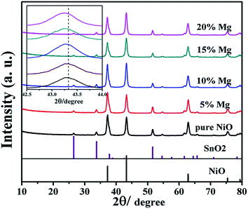 | ||
| Fig. 1 XRD patterns of pure NiO and Ni1−xMgxO (x = 0.05, 0.1, 0.15, 0.2) films coated on FTO glasses. | ||
Fig. 2a and b show the SEM images of the pure NiO, Ni0.9Mg0.1O film respectively. It is clear that the particle size of 10–15 nm and the porosity of the two films keep nearly unchanged. The results reflect that the surfactant directed self-assembly method is commonly valid to control the film morphologies irrelevant to the film composition. The high porosity of the films is generated by the decomposition of the surfactant micelles (block copolymer, Pluronic F108). Such organized porosity can facilitate dye absorption and electrolyte penetration. To analyse the chemical composition of the designed Ni0.9Mg0.1O film, elemental EDX mapping was employed to characterize the sintered film on Si wafer substrate. As shown in Fig. 2c–e, both Mg, and Ni elements are distributed homogeneously and the element percentages of Mg (5.05%), Ni (48.19%), and O (46.76%) are almost consistent with the concentrations of their source materials in the precursor and well consistent with their designed stoichiometric proportions. Ni1−xMgxO is easy to form homogeneous solid solutions, which have been widely reported previously.25,26
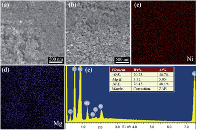 | ||
| Fig. 2 SEM image of (a) pure NiO, (b) Ni0.9Mg0.1O films. (c and d) EDS mapping results of Ni0.9Mg0.1O films of Ni and Mg elements and (e) its corresponding elemental analysis report. | ||
J–V curves of the p-DSCs using the series of mesoporous Ni1−xMgxO (x = 0, 0.05, 0.1, 0.15, 0.2) films as photocathodes are shown in Fig. 3. The resultant photovoltaic parameters are summarized in Table 1. An optimal efficiency of 0.19% was obtained by the Ni0.9Mg0.1O photocathode. It is noteworthy that the Ni0.9Mg0.1O based DSC possesses 85% higher efficiency than the NiO reference, ascribed to much higher Jsc (5.16 mA cm−2 versus 3.84 mA cm−2), decently higher Voc (109 mV versus 89 mV) and FF (0.34 versus 0.30) of the former. For a series of Ni1−xMgxO films, it is observed that by increasing Mg content, Jsc at first increases and reaches a maximum of 5.16 mA cm−2 with x = 0.1, and then gradually decreases; and FF shows the same tendency. While Voc increases from 89 mV to 116 mV monotonically as x increases from 0 to 0.2.
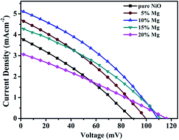 | ||
| Fig. 3 J–V characteristic curves of the p-type DSCs based on pure NiO, and Ni1−xMgxO ternary oxides with x = 0.05, 0.1, 0.15, 0.2 respectively. | ||
| Sample | Voc (mV) | Jsc (mA cm−2) | FF | η (%) |
|---|---|---|---|---|
| Pure NiO | 89 | 3.84 | 0.30 | 0.10 |
| 5% Mg | 100 | 4.72 | 0.32 | 0.15 |
| 10% Mg | 109 | 5.16 | 0.34 | 0.19 |
| 15% Mg | 112 | 4.32 | 0.33 | 0.16 |
| 20% Mg | 116 | 3.10 | 0.28 | 0.10 |
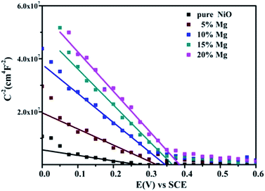
In order to clarify the reasons leading to higher Voc for the solar cells based on ternary oxides films. The Mott–Schottky analysis has been employed to measure the flat band potential (Vfb) of the Ni1−xMgxO films.21,27–30 The approximate Vfb can be obtained by fitting linear in the depletion zone of Mott–Schottky plot to get the intercept on the abscissa; and the concentration of charge carrier can be calculated from the slope of linear fits. From Fig. 4, the fitted linear plots have negative value, confirming that NiO and Ni1−xMgxO films are all with p-type semiconductivity.21,31 The results in Fig. 4 indicate a positive shift of Vfb with increasing Mg content. The Vfb of the pure NiO electrode is about 0.27 V (vs. SCE), whereas the Vfb of the Ni0.8Mg0.2O electrode increases a lot to 0.39 V. This positive shift of Vfb should be associated with the shift of valance band positions of the Ni1−xMgxO ternary oxides, which according to the literature could be explained by the Vegard's law.24 It is known that Voc of the DSC device is determined by the difference between the valance band of Ni1−xMgxO and the redox potential of the I−/I3− couple.21,32 Therefore, it is reasonable that Voc of DSCs increases due to positive shift of Vfb as Mg content increases.
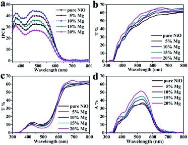
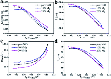
Regarding to the Jsc difference of the DSCs based on the series of Ni1−xMgxO (x = 0–0.2) films, their IPCE differences as shown in Fig. 5a can explain. The maximum IPCE at about 510 nm for the Ni0.9Mg0.1O based DSC is 44%, much higher than that of pure NiO (32%), Ni0.95Mg0.05O (40%), Ni0.85Mg0.15O (36%), and Ni0.8Mg0.2O (27%). It is known that light harvesting efficiency (LHE), injection efficiency from dye to semiconductor (Φinj), and charge collection efficiency (ηcc) all have contribution to the total IPCE, which determines Jsc according to equation, IPCE = LHE × Φinj × ηcc.22,23 The maximum IPCE and therefore Jsc achieved at x = 0.1 among the series of Ni1−xMgxO (x = 0–0.2) photocathodes could be explained as follows by balanced evaluation on those three factors. First, with respect to LHE, the optical transparency of the Ni1−xMgxO films increases as the Mg content increases (as shown in Fig. 5b), which can lead to steadily improvement on LHE. The higher transmittance should due to the partial remove of Ni2+ with intrinsic light absorption due to oscillator strength d–d interband transitions. The gradually increased optical band gap of Ni1−xMgxO compared with NiO could be another reason;24 besides, it is found that the dye adsorbing amount gradually increases as the Mg content increases (as reflected by the transmittance difference between the films before and after dye absorbing, Fig. 5c and d), which should be owing to the enhanced surface basicity of the films with more Mg surface atoms. Therefore, LHEs for the Ni1−xMgxO series photocathodes should monotonously increase as the increasing x from 0 to 0.2. Second, with respect to the charge collection efficiency of the compared photocathodes, as evaluated by the transient photovoltage/photocurrent decay techniques, the Ni0.9Mg0.1O film is found to be improved a little bit than that of pure NiO film in almost the whole applied potential range, which is due to slightly prolonged recombination time (Fig. 6a) and increased hole diffusion coefficient (Fig. 6c). These results can basically explain the improved FF of DSC based on Ni0.9Mg0.1O than that of NiO. Higher ηcc together with the improved LHE can well plain the higher IPCE and Jsc of DSC based on Ni0.9Mg0.1O than that of NiO. Interestingly, the detected charge collection property of Ni0.8Mg0.2O film is comparable to that of Ni0.9Mg0.1O (Fig. 6b and d), however, its measured IPCE and Jsc are much inferior. In view of that LHE of Ni0.8Mg0.2O is even higher than Ni0.9Mg0.1O, this contradiction should be explained by other reason. Plausibly, the driving force for hole injection, determined by the difference between the valance band of Ni1−xMgxO films and the HOMO level of P1 dye, is decreased as Mg content increases. The largely decreased hole injection efficiency from Ni0.9Mg0.1O to Ni0.8Mg0.2O may surpass the other two factors (i.e., LHE and ηcc) and dominate the lowest IPCE and Jsc of the corresponding solar cell.
Furthermore, the transient results in Fig. 6c also reflect that slight increasing the Mg doping level from NiO to Ni0.9Mg0.1O will not affect or even can increase the charge transport property of the film. But further increasing the doping level to Ni0.8Mg0.2O, hole diffusion inside the mesoporous film may be with increased difficulty. The gradually increased lifetime from NiO, Ni0.9Mg0.1O to Ni0.8Mg0.2O (Fig. 6c) is possibly due to the increased adsorbing density of dye molecular on the more basic surface of the semiconductors.
Conclusion
In summary, a series of ternary Ni1−xMgxO mesoporous films have been critically compared as photocathodes in p-DSCs. The surfactant directed self-assembly method for film preparation is facile to control the film's morphology and composition. These allow fair comparisons on physicochemical properties of the Ni1−xMgxO series films associated with Mg content tuning. It is found as x value increases from 0 to 0.2, the ternary film becomes more transparent and tends to adsorb more dye, which both lead to higher LHE of the solar cell. Flat band potential also shifts monotonously as x increases, which has two different impacts on the solar cell performance: first, Voc increases monotonously as x increases which is due to the potential difference between valance band of p-type semiconductor and redox potential of electrolyte becomes larger; second, the hole injection becomes a hindering factor when x = 0.2, because of too small driving force for hole injection, the consequence of which is the limited Jsc of the Ni0.8Mg0.2O based DSC. By balanced optimization of the above mentioned several factors, the maximum overall PCE of 0.19% was finally achieved by the Ni0.9Mg0.1O film, which is improved by 85% in comparison to the NiO based DSC with an efficiency of 0.10%. Transient photovoltage/photocurrent decays measurements reflect that the Ni0.9Mg0.1O film based DSC are superior in both facilitating hole transport and retarding interface recombination. Therefore, through this work, it is found that Ni0.9Mg0.1O film is a promising photocathode material alternative to pure NiO in p-DSCs.Acknowledgements
The authors would like to express sincere thanks for the financial supports by the National Natural Science Foundation (201103058, 201173091), 973 Program of China (2011CBA00703), Basic Scientific Research Funds for Central Colleges (2013TS040) and Beijing Key Laboratory for Sensors of BISTU (KF20131077208). We also thank Analytical and Testing Center of Huazhong University Science & Technology for the sample measurements.Notes and references
- F. Odobel, L. L. Pleux, Y. Pellegrin and E. Blart, Acc. Chem. Res., 2010, 43, 1063 CrossRef CAS PubMed.
- F. Odobel, Y. Pellegrin, E. A. Gibson, A. Hagfeldt, A. L. Smeigh and L. Hammarström, Coord. Chem. Rev., 2012, 256, 2414 CrossRef CAS PubMed.
- F. Odobel and Y. Pellegrin, J. Phys. Chem. Lett., 2013, 4, 2551 CrossRef CAS.
- E. A. Gibson, A. L. Smeigh, L. L. Pleux, L. Hammarström, F. Odobel, G. Boschloo and A. Hagfeldt, J. Phys. Chem. C, 2011, 115, 9772 CAS.
- H. Wang, X. Zeng, Z. Huang, W. Zhang, X. Qiao, B. Hu, X. Zou, M. Wang, Y.-B. Cheng and W. Chen, ACS Appl. Mater. Interfaces, 2014, 6, 12609 CAS.
- P. Qin, H. Zhu, T. Edvinsson, G. Boschloo, A. Hagfeldt and L. Sun, J. Am. Chem. Soc., 2008, 130, 8570 CrossRef CAS PubMed.
- P. Qin, M. Linder, T. Brinck, G. Boschloo, A. Hagfeldt and L. Sun, Adv. Mater., 2009, 21, 2993–2996 CrossRef CAS.
- L. Li, E. A. Gibson, P. Qin, G. Boschloo, M. Gorlov, A. Hagfeldt and L. Sun, Adv. Mater., 2010, 22, 1759 CrossRef CAS PubMed.
- A. Nattestad, A. J. Mozer, M. K. R. Fischer, Y.-B. Cheng, A. Mishra, P. Bäuerle and U. Bach, Nat. Mater., 2010, 9, 31 CrossRef CAS PubMed.
- S. Powar, T. Daeneke, M. T. Ma, D. Fu, N. W. Duffy, G. Götz, M. Weidelener, A. Mishra, P. Buerle, L. Spiccia and U. Bach, Angew. Chem., Int. Ed., 2013, 125, 630 CrossRef.
- S. Powar, Q. Wu, M. Weidelener, A. Nattestad, Z. Hu, A. Mishra, P. Bäuerle, L. Spiccia, Y.-B. Cheng and U. Bach, Energy Environ. Sci., 2012, 5, 8896 CAS.
- Z. Ji, M. He, Z. Huang, U. Ozkan and Y. Wu, J. Am. Chem. Soc., 2013, 135, 11696 CrossRef CAS PubMed.
- L. Li, L. Duan, F. Wen, C. Li, M. Wang, A. Hagfeldt and L. Sun, Chem. Commun., 2012, 48, 988 RSC.
- J. He, H. Lindström, A. Hagfeldt and S.-E. Lindquist, J. Phys. Chem. B, 1999, 103, 8940 CrossRef CAS.
- S. Powar, Q. Wu, M. Weidelener, A. Nattestad, Z. Hu, A. Mishra, P. Bauerle, L. Spiccia, Y.-B. Cheng and U. Bach, Energy Environ. Sci., 2012, 5, 8896 CAS.
- A. Morandeira, G. Boschloo, A. Hagfeldt and L. Hammarström, J. Phys. Chem. B, 2005, 109, 19403 CrossRef CAS PubMed.
- A. Nakasa, H. Usami, S. Sumikura, S. Hasegawa, T. Koyama and E. Suzuki, Chem. Lett., 2005, 34, 500 CrossRef CAS.
- A. Yella, H. W. Lee, H. N. Tsao, C. Yi, A. K. Chandiran, M. K. Nazeeruddin, E. W. G. Diau, C. Y. Yeh, S. M. Zakeeruddin and M. Grätzel, Science, 2011, 334, 629 CrossRef CAS PubMed.
- H. Wang, X. Zeng, Z. Huang, W. Zhang, X. Qiao, B. Hu, X. Zou, M. Wang, Y.-B. Cheng and W. Chen, ACS Appl. Mater. Interfaces, 2014, 6, 12609 CAS.
- D. Xiong, Z. Xu, X. Zeng, W. Zhang, W. Chen, X. Xu, M. Wang and Y.-B. Cheng, J. Mater. Chem., 2012, 22, 24760 RSC.
- D. Xiong, W. Zhang, X. Zeng, Z. Xu, W. Chen, J. Cui, M. Wang, L. Sun and Y.-B. Cheng, ChemSusChem, 2013, 6, 1432 CrossRef CAS PubMed.
- Z. Xu, D. Xiong, H. Wang, W. Zhang, X. Zeng, L. Ming, W. Chen, X. Xu, J. Cui, M. Wang, S. Powar, U. Bach and Y.-B. Cheng, J. Mater. Chem. A, 2014, 2, 2968–2976 CAS.
- J. Bai, X. Xu, L. Xu, J. Cui, D. Huang, W. Chen, Y. Cheng, Y. Shen and M. Wang, ChemSusChem, 2013, 6, 622 CrossRef CAS PubMed.
- J. Deng, M. Mortazavi, N. V. Medhekar and J. Z. Liu, J. Appl. Phys., 2012, 112, 123703 CrossRef PubMed.
- E. Cazzanelli, A. Kuzmin, N. Mironova-Ulmane and G. Mariotto, Phys. Rev. B: Condens. Matter Mater. Phys., 2005, 71, 134415 CrossRef.
- Y. Guo, L. Zhu, J. Jiang, Y. Li, L. Hu, H. Xu and Z. Ye, Thin Solid Films, 2014, 558, 311 CrossRef CAS PubMed.
- X. Feng, K. Shankar, M. Paulose and C. Grimes, Angew. Chem., 2009, 121, 8239 CrossRef.
- X. Lu, X. Mou, J. Wu, D. Zhang, L. Zhang, F. Huang, F. Xu and S. Huang, Adv. Funct. Mater., 2010, 20, 509 CrossRef.
- J. Liu, H. Yang, W. Tan, X. Zhou and Y. Lin, Electrochim. Acta, 2010, 56, 396 CrossRef CAS PubMed.
- K.-P. Wang and H. Teng, Phys. Chem. Chem. Phys., 2009, 11, 9489 RSC.
- G. Natu, P. Hasin, Z. Huang, Z. Ji, M. He and Y. Wu, ACS Appl. Mater. Interfaces, 2012, 4, 5922 CAS.
- A. Usami, S. Seki, Y. Mita, H. Kobayashi, H. Miyashiro and N. Terada, Sol. Energy Mater. Sol. Cells, 2009, 93, 840 CrossRef CAS PubMed.
Footnote |
| † These two authors contribute equally to this paper. |
| This journal is © The Royal Society of Chemistry 2014 |

