
A Raman spectroscopic study of uranyl minerals from Cornwall, UK†
R. J. P. Driscolla,
D. Wolverson*a,
J. M. Mitchelsa,
J. M. Skeltona,
S. C. Parkera,
M. Molinaria,
I. Khanb,
D. Geesonb and
G. C. Allenc
aUniversity of Bath, Claverton Down, Bath, UK. E-mail: D.Wolverson@bath.ac.uk
bAWE, Aldermaston, Reading, UK
cInterface Analysis Center, University of Bristol, Bristol, UK
First published on 31st October 2014
Abstract
In the fields of nuclear forensics, geology and environmental science, it is important to be able to rapidly identify an unknown sample of uranyl mineral. Raman spectroscopy provides a fast, non-destructive and portable strategy for collecting data, which can then be compared against a set of known experimental information. We present a Raman study of a selection of uranyl minerals from Cornwall, UK. This includes the first Raman spectrum published for the uranyl arsenate mineral, nová![[c with combining breve]](https://www.rsc.org/images/entities/char_0063_0306.gif) ekite. These spectra were collected under a standard set of conditions, using three excitation wavelengths, 325, 532 and 785 nm, the latter typically providing spectra with little fluorescence and the best resolution. The vibrational properties of these minerals are characterised by the symmetric stretching mode of the uranyl cation, seen between 750–900 cm−1, though the exact position varies with respect to the local environment. To discriminate between samples, the rest of the spectrum must be considered; the poly-anions in the structure provide a fingerprint set of Raman bands. An added complication occurs when samples of the same mineral from different mines demonstrate variations in their Raman spectra; this emphasises the need for data to be collected from a variety of locations, but also suggests that other experimental techniques could provide complementary information.
ekite. These spectra were collected under a standard set of conditions, using three excitation wavelengths, 325, 532 and 785 nm, the latter typically providing spectra with little fluorescence and the best resolution. The vibrational properties of these minerals are characterised by the symmetric stretching mode of the uranyl cation, seen between 750–900 cm−1, though the exact position varies with respect to the local environment. To discriminate between samples, the rest of the spectrum must be considered; the poly-anions in the structure provide a fingerprint set of Raman bands. An added complication occurs when samples of the same mineral from different mines demonstrate variations in their Raman spectra; this emphasises the need for data to be collected from a variety of locations, but also suggests that other experimental techniques could provide complementary information.
1 Introduction
In the uranium mining industry, the most important and economically valuable mineral is the insoluble uranium oxide uraninite (UO2).1 However, during the mining process or natural weathering, some of the mineral can be exposed to oxidising conditions, forming the soluble uranyl (UO22+) cation.2 The mobility of the uranyl cation allows a wide variety of secondary minerals to crystallise, typically as layered systems with different polyanions and cations, altering the chemistry and structure of the crystal.Due to the dangers associated with radioactivity, along with the widespread presence of uranyl minerals, it is important for governments and international agencies to keep track of nuclear materials, as well as having the capability to identify unknown samples. The field of nuclear forensics has built up a range of strategies designed to answer the questions of chemical composition and history of radioactive samples.3 Therefore, it is of particular interest to maintain an extensive database of information about uranyl minerals from a variety of geographical locations, which can be used to aid forensic scientists in the identification of an unknown sample and its origin. The RRUFF Project4 is a collection of Raman and infrared spectroscopic data, in addition to X-ray diffraction (XRD) and energy dispersive X-ray spectroscopy (EDX) results, gathered for a wide variety of minerals. However, the data available for uranyl minerals, including those from Cornwall, UK, is currently lacking. The information does not have to be limited to Raman spectroscopy; it has been noted that different experimental techniques can provide complementary data, narrowing the identity of an unknown to a smaller selection of possibilities.3 For example, the mass spectrometry techniques of secondary ion mass spectrometry (SIMS), thermal ion mass spectrometry (TIMS) and inductively coupled plasma mass spectrometry (ICPMS) can provide information about the isotopic ratio, while EDX can be used to characterise the chemical composition. A visual inspection of the sample can also provide information about the crystal colour, morphology, and the presence of other associated minerals of interest. Through the use of multiple techniques, it is possible to build up a more complete understanding of the sample.
The use of such a database is not restricted to the field of forensics; it would also be of interest when studying the transport of uranium in the environment or investigating patterns in the formation of minerals at different localities around the world. While the set of minerals in this study originated from Cornwall, there are many other regions where such minerals can be found, including Australia,5 Portugal,6 the Czech Republic,7,8 Germany,9 France10 and the Congo.2,11 The topography of Cornwall is dominated by a backbone of granitic rock, known as a batholith, which intruded into the original sedimentary rock. The largest surface intrusion of the Cornish batholith is the granite mass at Dartmoor, Devon.12 A more detailed examination of the geology in the region shows an extensive variety of igneous and metamorphic rocks, in addition to secondary minerals. These minerals were typically formed after the granite intrusion, which heated the surrounding water, leaching metallic elements from the surrounding rocks and focusing them into fractures or faults. As the area cooled, both minerals and ores were deposited.13 A variety of ores have been mined in the region, most notably tin and copper, but also lead, silver, tungsten, arsenic and uranium.12 It is this wide selection of elements that allows for such a large number of different uranyl minerals to exist; as other countries have their own unique geology, it is likely that compositional or structural differences in the minerals can provide insight in to their origin.
A number of studies have been performed on uranyl minerals, using techniques such as infrared spectroscopy,14 atomic force microscopy (AFM)2 and XRD.6,15–18 Comparatively little work has been done using Raman spectroscopy as an investigative tool, with the exception of Frost et al.10,19–22 Those studies used both Raman and infrared spectroscopy as complementary techniques, also investigating the effects of temperature on the spectra, particularly on the bands corresponding to water.18,23,24
Raman spectroscopy has proven to be valuable for the detection of dangerous and illicit materials. It can analyse very small sample sizes through the use of a microscope25 and it is possible to scan delicate systems as it is usually non-destructive. The mineral samples of interest here often contain up to 12 water molecules per formula unit, with dehydration in some structures beginning at room temperature.24 In addition, the existence of portable Raman devices has allowed data to be collected in the field, providing information on samples that are too fragile or difficult to transport, as well as acting as an initial screening probe for samples of interest.26 The polyanions present in uranyl minerals, e.g. PO43−, CO32− or SO42−, and the uranyl cation itself, produce strong, characteristic bands in Raman spectra, which are ideal for discriminating between the different minerals.
The aim of the present investigation is to address whether Raman spectroscopy can be useful in discriminating between different uranyl minerals and providing insight into their different structural properties. We have begun to measure the vibrational properties of a variety of uranyl minerals from Cornwall, UK, under standard sets of experimental conditions. Whereas previous Raman studies were performed using a visible excitation (e.g. 633 nm),10,19–22 we have collected data using three excitation wavelengths, including visible, near-infrared and ultraviolet lasers, allowing us to compare the spectra from each. We also present the Raman spectrum of the uranyl arsenate mineral, nováekite, which we believe has not been reported before.
We present the minerals studied, in different classes based on their composition and structure, including uranyl phosphate and arsenate minerals, carbonate minerals, sulphate minerals, silicate minerals and uranyl hydrate minerals. For each set of minerals, a representative Raman spectrum is given alongside a comparison with previously published data. A discussion is then given on the main features of the spectra of these minerals, including the uranyl symmetric stretching mode (Section 4.1) and the polyanion peaks (Section 4.2). We conclude with a discussion of the optimum choice of excitation wavelength (Section 4.3).
2 Experimental methodology
2.1 Mineral samples studied
Table 1 lists the mineral samples studied, alongside the expected chemical formulae and provenance. Every mineral was collected from Cornwall, UK, except for the autunite sample from Merrivale Quarry, which is in the neighbouring county of Devon. Fig. 1 shows photographs of the mineral samples.| Mineral name | Literature formula | Provenance |
|---|---|---|
| a A number of possible chemical formulae have been suggested for phosphuranylite; this formula was presented by Ryback and Tandy for a sample of phosphuranylite from Wheal Edward.29 | ||
| Autunite | Ca(UO2)2(PO4)2·11H2O | Merrivale Quarry, Tavistock27 |
| Torbernite | Cu(UO2)2(PO4)2·12H2O | Bunny Mine, Stenalees, St. Austell28 |
| Zeunerite | Cu(UO2)2(AsO4)2·12H2O | Wheal Gorland, Redruth28 |
| Nováekite |
Mg(UO2)2(AsO4)2·10H2O | Wheal Edward, St. Just16,29 |
| Phosphuranylitea | Ca(UO2)3(PO4)2(OH)2·6H2O | Wheal Edward, St. Just29 |
| Andersonite | Na2Ca(UO2)(CO3)3·6H2O | Geevor Mine, Pendeen17,29 |
| Schröckingerite | NaCa3(UO2)(CO3)3(SO4)F·10H2O | Geevor Mine, Pendeen17,29 |
| Johannite | Cu(UO2)2(OH)2(SO4)2·8H2O | Geevor Mine, Pendeen17 |
| Natrozippeite | Na5(UO2)8(SO4)4O5,(OH)3·8H2O | Geevor Mine, Pendeen29 |
| Uranophane | Ca(UO2)2(SiO3OH)2·5H2O | Wheal Edward, St. Just15 |
| Cuprosklodowskite | Cu(UO2)2(SiO3OH)2·6H2O | West Wheal Owles, St. Just15 |
| Kasolite | Pb(UO2)(SiO4)·H2O | Loe Warren Zawn, St. Just30 |
| Compreignacite | K2(UO2)6O4(OH)6·7H2O | West Wheal Owles, St. Just15 |
 | ||
| Fig. 1 Photographs of the mineral samples studied in this investigation: (a) yellow crystals of autunite; (b) green crystals of torbernite; (c) yellow flakes of nováekite; (d) green crystals of zeunerite; (e) yellow crust of phosphuranylite; (f) yellow aggregates of andersonite; (g) pale yellow aggregates of schröckingerite; (h) yellow crust of natrozippeite; (j) yellow crust of uranophane; (k) dark yellow crystals of compreignacite; (m) pale green crystals of cuprosklodowskite; (n) orange-red crust of kasolite and (o) green crystals of johannite. Typically, the full samples are approximately 4–7 cm across. | ||
The majority of uranyl mineral samples are a yellow or green colour; some form distinct crystals or deposits (e.g. torbernite and andersonite), while others instead form a crust on the surface of the primary rock sample (e.g. uranophane and phosphuranylite). More information on the physical appearance of each sample is given in the ESI Section 1.†
Elton and Hooper identified the crystal structure and compositions of several of the mineral samples using a combination of X-ray powder diffraction and energy-dispersive X-ray spectroscopy.15–17 For the remaining minerals, the atomic ratios found in the EDX spectra typically agree with established literature formulae.
Appropriate safety procedures are in place in the laboratory where this research has been carried out, including checking the dose for each sample. The dose for the majority of samples was below 5 μSv h−1, while the highest doses were for uranophane and compreignacite, both of which were below 20 μSv h−1.
2.2 Raman spectroscopy
Raman spectra were recorded with a Renishaw inVia Raman spectrometer, with three lasers for excitation: 325 nm (KIMMON, He–Cd laser, 270 mW at source), 532 nm (Renishaw, diode laser, 380 mW at source) and 785 nm (Renishaw, diode laser, 370 mW at source). The acquisition time for each scan and the number of accumulations were varied to improve the signal-to-noise ratio. Additionally, a large percentage (typically greater than 95%) of the laser power was attenuated in order to prevent damage to the sample. The spectral resolution differed with the laser wavelength used (±5 cm−1 for 325 nm, ±1.2 cm−1 for 532 nm and ±0.2 cm−1 for 785 nm), which resulted from the different diffraction gratings used. Spectra were typically collected using ×5 and ×50 long-focus objectives (LEICA) for the 532 and 785 nm lasers, as well as a ×15 long-focus fused silica objective (THORLABS), designed for the 325 nm laser. Calibration of the spectrometer for the 532 and 785 nm lasers was carried out using the 520 cm−1 line of silicon, while the spectrometer was calibrated for the 325 nm laser using the 1332 cm−1 peak of a cubic diamond. Data acquisition was carried out using the Renishaw WiRE software package.To assist in the analysis of the Raman spectra, we used a custom peak-fitting algorithm to identify and characterise the major spectral features. The fitting routine proceeds in two stages. In the first, the spectrum is divided into 5 equal segments, each of which is fitted to a slope to approximate the average spectral intensity in that region. Bands with intensities above 1.05 times this line are temporarily removed, and the remaining complete spectrum is then smoothed with an 11-point median filter, and the smoothed spectrum fitted to a 10-power polynomial to obtain a background function.
In the second step, the background polynomial is subtracted and the peaks in customisable regions of interest (ROIs) are found. In each ROI, the baseline intensity is again fitted to a slope, with intensities 1.1 times the average within the region being excluded from the fit. An 11-point triangle filter is applied, and candidate peaks are identified from intensity maxima in the smoothed spectrum. Those within 1.5 multiples of the baseline are discarded, and the remaining are fitted to a sum of Lorentzian functions, initialised with one function positioned at the centre of each candidate peak, scaled to match the peak height and with an initial full width at half maximum (FWHM) of 5.0 cm–1. The peaks are optimised against the unsmoothed spectrum with the baseline slope subtracted, using a least-squares algorithm. Finally, functions in the optimised set whose centres fall outside their ROI are discarded.
The algorithm returns the coefficients of the background polynomial and peak functions, the latter of which serve as a peak table providing the position, intensity, and FWHM of major spectral features. By testing a subset of the spectra for each mineral sample and visually comparing the original and fitted spectra, we confirmed that, with these parameters and ROIs set to 100–1200 cm−1 this fitting routine could successfully identify and characterise all the major peaks across a wide variety of spectra.
2.3 Energy dispersive X-ray spectroscopy
Energy-dispersive X-ray spectroscopy (EDX) analyses were performed using a JEOL 6480 LV Scanning Electron Microscope, equipped with an Oxford Instruments INCA X-act silicon drift detector. Both secondary electrons (SE) and backscattered electrons (BSE) were detected. The single crystal samples were fixed to an aluminium sample mount using conductive carbon tape (Agar Scientific), then dried in a dessicator for 24 hours. The samples were studied under low vacuum (45 Pa) to prevent a build up of charge on the surface of the sample, which could result in heating; this also avoided the need to cover the sample in a conductive coating. The EDX spectra were optimised using a copper standard, allowing quantitative data to be collected.There were a number of limitations associated with the use of EDX, particularly in the collection of quantitative data. The percentages of carbon and oxygen were always higher than anticipated from the chemical formula; it is likely that these were present within the microscope or as contaminants on the surface of the sample. An additional difficulty is the close association of the mineral samples with the host rock, resulting in the detection of certain elements, including silicon, aluminium and iron, that would not be expected by the chemical formula. Internally stored empirical standards were used to determine the ratios of atoms in each mineral, accurate to ±1%.31
3 Results
In the following sections, a description of each mineral structure is given and a representative Raman spectrum is presented. The quantity of background noise and fluorescence varied across the different excitation wavelengths, so these Raman spectra are shown with the excitation wavelength that produced the best signal-to-noise ratio for each mineral. The fitted peak positions for each of the spectra in the set have been averaged and tables listing the peaks for each mineral are in the ESI,† a description of the most relevant features is given in the following subsections. Spectra are shown within the 100–1200 cm−1 region for each mineral, as there are few features at higher wavenumbers. The exceptions are typically related to water vibrations, although these bands can be studied more accurately by infrared rather than the Raman. This is illustrated in Section 4.3, where the spectrum of kasolite from 0–4000 cm−1 is shown for all three excitation wavelengths. The EDX spectra collected typically agree with the original assignments.15–17,29 The EDX results are given in the ESI: Table SI14† gives the average atomic percentages across a number of spectra for each mineral and Table SI15† presents the theoretical compositions and compares them to the EDX estimates.3.1 Uranyl phosphates and arsenates
The uranyl phosphates and arsenates are the most common and diverse category of uranyl minerals. There are four major classifications, including the autunite group (Section 3.1.1)19 and the phosphuranylite group (Section 3.1.2).32,33The four autunite mineral samples analysed were identified as autunite (Ca(UO2)2(PO4)2·nH2O), torbernite (Cu(UO2)2(PO4)2·nH2O), nováekite (Mg(UO2)2(AsO4)2·nH2O) and zeunerite (Cu(UO2)2(AsO4)2·nH2O). We are not aware of any previously published Raman spectra for the arsenate mineral nováekite, so this sample is compared against spectra of its phosphate analogue, saléeite. The autunite spectra (Fig. 2) correspond well to those seen in the literature.18,19,24
 | ||
| Fig. 2 Representative Raman spectra of autunite, torbernite, nováekite and zeunerite mineral samples. The 100–700 cm−1 region has been rescaled, to emphasise the bands in this region. The wavelengths displayed correspond to the optimum excitation for each mineral. The major peaks are annotated, while all bands are listed in Tables SI1–4.† | ||
The phosphorus to arsenic ratios for the four autunite minerals have been calculated from EDX as 7.4![[thin space (1/6-em)]](https://www.rsc.org/images/entities/char_2009.gif) :1 for autunite, 38:1 for torbernite, 1:3.7 for nováekite and 1:4.2 for zeunerite (Table SI14†). This demonstrates that, although all four samples contain a mixture of phosphorus and arsenic, autunite and torbernite are primarily phosphate minerals, whereas zeunerite and nováekite are largely arsenates.
:1 for autunite, 38:1 for torbernite, 1:3.7 for nováekite and 1:4.2 for zeunerite (Table SI14†). This demonstrates that, although all four samples contain a mixture of phosphorus and arsenic, autunite and torbernite are primarily phosphate minerals, whereas zeunerite and nováekite are largely arsenates.
For the minerals autunite and nováekite, the 785 nm excitation laser produced spectra with little fluorescence, while the 532 nm spectra typically had a significant amount. In contrast, all three lasers (325, 532 and 785 nm) produced good quality spectra for both torbernite and zeunerite samples; for torbernite, the 532 nm spectra produced better resolved peaks, while there was no difference between the two visible lasers for zeunerite. For all minerals, however, no modes were observed in the bending region (below 600 cm−1) of the 325 nm excitation spectra.
The most intense peak in the Raman spectrum of every autunite mineral is the uranyl symmetric stretching mode (v1(UO2)2+), seen at 830 cm−1 in autunite, 825 cm−1 in torbernite, 817 cm−1 in nováekite and 821 cm−1 in zeunerite; in the 785 nm spectra of autunite and the 532 nm spectra of torbernite, this mode also has a low intensity shoulder. The v2(UO2)2+ bending mode and v3(UO2)2+ antisymmetric stretch are seen between 200 and 300 cm−1 and around 900 cm−1, respectively. The bending modes are not visible in the 325 nm spectra, but in contrast, the uranyl antisymmetric stretch is actually more noticable in the 325 nm spectra of torbernite (Table SI2†).
The phosphate antisymmetric stretching mode (v3(PO4)3−) is seen strongly in autunite and torbernite, as reported in previous studies.19 It is sometimes seen as a single peak about 1000 cm−1, but sometimes splits into two separate bands around 990 cm−1 and 1010 cm−1. This splitting may be due to the anion losing its perfectly tetrahedral symmetry and consequently the degeneracy of its antisymmetric stretches. For the mineral autunite, the splitting was most prominent in the 785 nm spectra, whereas a single, broad band was visible in the 325 nm spectra. In the nováekite spectra, there is a low intensity peak in this region, which can be explained by the presence of some phosphorus, as also indicated by the EDX spectra.
The phosphate symmetric stretching mode (v1(PO4)3−) is expected between 930–950 cm−1, but no peak is visible in this range. This absence has been reported previously,23 although the exact cause is uncertain. The phosphate or arsenate bending modes, seen within the 300–650 cm−1 region, are sometimes visible as very low intensity bands in the 532 and 785 nm spectra, corresponding to similar peaks in the literature.19 Those corresponding to the arsenate group are typically found at a lower wavenumber than the phosphate modes.
The mineral phosphuranylite has been assigned a range of formulae: Demartin et al.40 suggested KCa(H3O)3(UO2)7(PO4)4O4·8H2O, Piret et al. proposed Ca(UO2)7(PO4)4(OH)4·12H2O,41 while Ca(UO2)3(PO4)2(OH)2·6H2O was previously assigned to a sample from Wheal Edward, St. Just.29 The EDX spectrum of this sample gives a composition of approximately K0.7Ca1.3(UO2)3(PO4)1.9, which has a very similar U/P ratio (1.5) to that of the formula given for the published Wheal Edward sample.29 However, the presence of both potassium and calcium indicates there are similarities to the composition given by Demartin et al.40 Since the proportion of cations is higher than expected, it is possible that some of these originate from the host rock.
The strongest band in the Raman spectrum of phosphuranylite (Fig. 3) is the uranyl symmetric stretching mode, seen at 801 cm−1. This is the only distinct peak in the 325 nm spectra, where the signal-to-noise ratio is very low, resulting in a lot of background noise (Fig. SI5†). In an investigation by Frost et al.,5 three individual samples of phosphuranylite were studied, from Minerva Heights and Saddle Ridge Mines, Australia, and Ruggles Mine, USA. The Raman spectra collected for each had four Raman bands in the region expected for the uranyl symmetric stretch: 816, 837, 843 and 847 cm−1 for Saddle Ridge, 812, 817, 832 and 841 cm−1 for Ruggles Mine and 768, 793, 805 and 815 cm−1 for Minerva Heights.5 Whereas the Ruggles Mine and Saddle Ridge samples produced similar spectra, the Raman bands seen in the Minerva Heights sample were closer to those in this investigation. A low intensity band is seen in some spectra at about 216 cm−1, related to the uranyl bending mode. In contrast to the autunite minerals, no low intensity bands are seen around 900 cm−1, corresponding to the uranyl antisymmetric stretch for phosphuranylite.
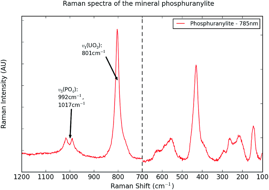 | ||
| Fig. 3 A representative Raman spectrum of the mineral phosphuranylite. The 100–700 cm−1 region has been rescaled, to emphasise the bands in this region. The 785 nm excitation produced the best spectrum, and is shown here. The major peaks are annotated, while all bands are listed in Table SI5.† | ||
The 785 nm laser has proven the best for collecting Raman spectra from the sample of phosphuranylite, as the background fluorescence is minimal and more detail can be seen in the spectra. In a number of these spectra, bands are present around 992 and 1017 cm−1, likely due to the antisymmetric stretching mode (v3(PO4)3−) of the phosphate group.5 In the 532 nm spectra, the phosphate stretch is only visible as a low intensity, broad band around 1000 cm−1. As with the autunite minerals, the phosphate symmetric stretch (v1(PO4)3−) is not clearly visible in these spectra, for which no definitive explanation is known. A strong mode about 435 cm−1 in spectra collected using the visible wavelengths can be identified as the phosphate bending mode (v2(PO4)3−).
3.2 Uranyl carbonates
A large number of publications are available on the uranyl carbonate minerals; they have been studied intensively and many can be readily synthesised.20,42,43 They can be classified according to the number of carbonate anions within each formula unit or the presence of other anions in the system. Both andersonite20 and schröckingerite44 have uranyl tricarbonate clusters, which consist of three bidentate carbonate anions coordinated around the uranyl equatorial plane.The chemical formula of andersonite is Na2Ca(UO2)(CO3)3·6H2O; the uranyl tricarbonate clusters form a complex framework structure with the cation-oxygen polyhedra.20 The mineral schröckingerite has the formula NaCa3(UO2)(CO3)3(SO4)2F·10H2O. The uranyl tricarbonate clusters, the SO4 tetrahedra and the cation-oxygen octahedra form a layered structure.17 For both crystal structures, water molecules are located within the channels and the interlayer space, respectively.
EDX spectroscopy proved unreliable in calculating the proportion of carbon for the two carbonate minerals, as there was a significant percentage in every mineral spectrum. Another issue is seen with andersonite, where the calcium ratio is higher than the expected value and both fluorine and sulphur are present. These inconsistencies may be attributed to a transparent layer of gypsum crystals (CaSO4·2H2O), known to be associated with these samples and to the host rock, which may include fluorspar (CaF2).
When collecting spectra for the two carbonate minerals, all three laser wavelengths produced similar spectra; those with the 532 nm laser had some fluorescence bands, but the peaks remained distinct (Fig. 4). The 325 nm spectra typically displayed the same peaks as the 532 and 785 nm spectra (Fig. SI6 and SI7†).
 | ||
| Fig. 4 Representative Raman spectra of the uranyl carbonate minerals andersonite and schröckingerite. The 100–700 cm−1 region has been rescaled, to emphasise the bands in this region. The wavelengths displayed correspond to the optimum excitation for each mineral. The major peaks are annotated, while all bands are listed in Tables SI6 and SI7.† | ||
The uranyl symmetric stretching bands are seen at 833 cm−1 for andersonite and 815 cm−1 for schröckingerite, which agree closely to the literature values,20,44 but for schröckingerite a low intensity shoulder is also present. No uranyl bending modes are consistently present, but a low intensity band is sometimes seen around 905 cm−1, assigned to the uranyl antisymmetric stretch.
The peaks in andersonite and schröckingerite at 1092 cm−1 are attributed to the carbonate symmetric stretch, which also has a low wavenumber shoulder in the andersonite spectra. The sulphate symmetric stretch is also visible in all spectra of schröckingerite at 984 cm−1; a second sulphate band is also visible at 1009 cm−1 in the 532 and 785 nm spectra. A band is seen in both mineral spectra about 743 cm−1, which may be attributed to the carbonate bending mode.
3.3 Uranyl sulphates
Johannite and natrozippeite are both uranyl sulphate minerals; the uranyl cations in each are coordinated to a combination of SO42−, O2− and OH− anions. However, the sheet structure of each mineral is different. Whereas natrozippeite is part of the zippeite group, consisting of chains of uranyl polyhedra, the johannite sheet contains pairs of uranyl polyhedra. The structures and Raman spectra of johannite and natrozippeite are discussed in Sections 3.3.1 and 3.3.2, respectively.:1.21 In contrast to the other minerals, the cation concentration was higher than the formula would suggest, but many Cornish mines are rich in copper and it is likely that the host rock contains copper ores.All three excitation lasers produced good Raman spectra for the sample of johannite, though there were no bending modes seen in the 325 nm spectra and the stretching modes were less well resolved.
A strong uranyl symmetric stretch is observed at 836 cm−1 (Fig. 5), which is at a significantly higher wavenumber than those assigned previously (756, 788 and 812 cm−1).21 This variation might be due to differences in the mineral composition. Low intensity bands are also seen in some spectra in the region expected for the uranyl bending mode, but none were seen for the antisymmetric stretch.
 | ||
| Fig. 5 Representative Raman spectra of the uranyl sulphate minerals johannite and natrozippeite. The 100–700 cm−1 region has been rescaled, to emphasise the bands in this region. The wavelengths displayed correspond to the optimum excitation for each mineral. The major peaks are annotated, while all bands are listed in Tables SI8 and SI9.† | ||
Sulphate stretching modes are present in the spectra between 1000 and 1100 cm−1; peaks are seen at 1045 and 1095 cm−1 in the 532 and 785 nm spectra, the latter very similar to the mode seen for the sample of schröckingerite. In the 532 nm spectra, the 1095 cm−1 peak has a shoulder, while a low intensity mode is also present in a small number of spectra at 1012 cm−1. Additionally, some low intensity bands are also present within the 350 to 500 cm−1 region, assigned to sulphate bending modes (v2(SO4)2−); these are better resolved in the 532 nm spectra, though most are visible in the 785 nm spectra as well.
:1 ratio of uranium to sulphur. They can be distinguished by the monovalent or divalent cations located between the sheets. The uranyl cation is found in a pentagonal bipyramid environment, composed of sulphate and oxygen (or hydroxide) ions; these uranyl polyhedra are arranged in chains, two polyhedra wide and connected by sulphate tetrahedra. Natrozippeite is the most common member of the zippeite group, with a formula of Na5(UO2)8(SO4)4O5,(OH)3·8H2O.8,45–47 Synthetic samples of natrozippeite have also been given the formula Na4(UO2)6(SO4)3(O,OH)10·4H2O.48,49 The exact quantity of cations (e.g. Na+, K+) is also uncertain and a number of authors have mentioned that the ratio of cation to uranium in natural samples is lower than expected from the stoichiometry.47,49,50 The EDX spectrum for natrozippeite from Geevor mine also displays a sodium deficiency, as well as confirming the 2:1 ratio of uranium to sulphur in the system.For the sample of natrozippeite, the 532 nm excitation produced spectra with high background fluorescence, preventing peak identification. The 785 nm excitation wavelength produced the best spectra (Fig. 5), while those collected using the 325 nm laser had a poor signal-to-noise ratio.
The uranyl symmetric stretching mode was seen as an asymmetric peak around 840 cm−1 in this sample of natrozippeite, indicating the presence of multiple bands, which agrees well with the literature spectra (813, 823, 834, 840 and 841 cm−1).47 This was the only mode seen in the 325 nm spectra. A low intensity mode was occasionally visible around 250 cm−1, relating to the uranyl bending mode, while no bands were present for the antisymmetric stretch.
Sulphate modes were seen at 1013 cm−1, corresponding to the symmetric stretch and at 397 cm−1, assigned to the bending mode (v2(SO4)2−).
3.4 Uranyl silicates
Uranophane, kasolite and cuprosklodowskite are members of the uranophane group of uranyl silicates. They each adopt a layered structure with an equal ratio of UO2 to SiO4; the uranyl cations are located in a pentagonal bipyramidal environment, with three corner-sharing and one edge-sharing silicate tetrahedra.22 Uranophane has the chemical formula Ca(UO2)2(SiO3OH)2·5H2O, cuprosklodowskite is Cu(UO2)2(SiO3OH)2·6H2O and kasolite is Pb(UO2)(SiO4)·H2O. The EDX spectra collected for these minerals agrees with the original assignments given in the literature. The only notable difference is the proportion of silicon to uranium in the composition, which should be 1:1.22 The ratios seen in the EDX indicates a higher level of silicon than uranium, which may be attributed to the host rock.
For the mineral uranophane, the 785 nm excitation laser produced the best spectra, but despite high fluorescence in the 532 nm and low signal strength in the 325 nm spectra, some peaks are seen consistently. For cuprosklodowskite and kasolite, there are few differences between the 532 and 785 nm spectra, though the 532 nm laser produces a stronger signal for cuprosklodowskite. As with the other minerals, there is some loss of resolution in the 325 nm spectra and no bending modes are visible.
The uranyl symmetric stretch (v1(UO2)2+) for each member of the uranophane group tends to be at a lower wavenumber than other uranyl minerals (Fig. 6); it is seen as a sharp peak about 800 cm−1 for uranophane, a broader, asymmetric peak about 792 cm−1 for cuprosklodowskite and a sharp peak at 760 cm−1 for kasolite. Low intensity bands are sometimes visible between 200 and 300 cm−1, which are also visible in some literature spectra, corresponding to the uranyl bending mode.22 Low intensity bands were also detected between 850 and 920 cm−1, assigned to the uranyl antisymmetric stretching mode.
 | ||
| Fig. 6 Representative Raman spectra of the uranyl silicate minerals uranophane, kasolite and cuprosklodowskite. The 100–700 cm−1 region has been rescaled, to emphasise the bands in this region. The wavelengths displayed correspond to the optimum excitation for each mineral. The major peaks are annotated, while all bands are listed in Tables SI10–12.† | ||
Peaks seen in the region of 939 to 974 cm−1 for the uranophane minerals correspond well to the silicate antisymmetric stretching modes seen in the literature spectra.22 These are stronger and more distinct in the 532 and 785 nm spectra, with two bands seen for kasolite; this distinction is lost in the 325 nm spectra, where only a single, broad band is visible. Low intensity bands have also been noted in some spectra, between about 350 and 550 cm−1, where the silicate bending modes may be expected.22 No obvious peaks are present for the silicate symmetric stretch, similar to the phosphate symmetric stretching mode in the autunite phosphates.
3.5 Uranyl hydrates
The uranyl oxide hydrate mineral compreignacite (K2(UO2)6O4(OH)6·7H2O) adopts a sheet structure consisting of edge- and corner-shared uranyl pentagonal bipyramids, formed from both oxygen and hydroxide anions. The other cations are coordinated to water molecules in the interlayer space.10,51 As the mineral composition is primarily oxygen and hydrogen, very little accurate information could be gained from EDX. It was noted, however, that the ratio of uranium to potassium is higher than expected, indicating a significant cation deficiency. This ratio may have been further distorted by the presence of associated uranium minerals present on the sample, particularly the sample of cuprosklodowskite, or by uranium in the host rock.For the compreignacite samples, the 785 nm excitation laser typically produced spectra with the least fluorescence. The 532 nm spectra often contained a flourescence band over the region under investigation, however, this was typically weak, allowing detailed Raman bands to be seen. In contrast, the 325 nm excitation spectra tended to be much weaker.
The most significant Raman peak seen for the compreignacite sample (Fig. 7) is the uranyl symmetric stretching mode at 834 cm−1. An additional smaller peak, or shoulder, is sometimes seen around 804 cm−1 in 785 nm spectra or 858 cm−1 in 325 nm spectra. Other bands are seen in both 532 and 785 nm spectra, though the latter wavelength provided a higher signal-to-noise ratio. The most consistent bands are seen at 549, 460, 402, 329 and 204 cm−1; the majority may be linked to the bending and stretching of equatorial uranium–oxygen interactions, while the 204 cm−1 band can be assigned to the uranyl bending mode.
 | ||
| Fig. 7 A representative Raman spectrum of the uranyl hydrate mineral compreignacite. The 100–700 cm−1 region has been rescaled, to emphasise the bands in this region. The 785 nm excitation produced the best spectrum, which is shown here. The major peaks are annotated, while all bands are listed in Table SI13.† | ||
4 Discussion
4.1 The uranyl symmetric stretching mode
We have collected Raman spectra from a selection of uranyl minerals, each with a unique set of vibrational modes, but each mineral has a prominent uranyl symmetric stretching mode (v1(UO2)2+). The exact position of this peak has varies the range of minerals and may be used to discriminate between them. Table 2 summarises the measured v1(UO2)2+ modes, together with literature values. For all minerals, the v1(UO2)2+ mode was found to depend upon the poly-anions coordinated to the equatorial plane of the uranyl group. A distinct trend is seen between the uranyl silicate (SiO44−), uranyl phosphate (PO43−) and uranyl sulphate (SO42−) minerals, where an increase in the poly-anion charge leads to a decrease in the Raman shift of the uranyl symmetric stretch. Within each class of minerals there are also small differences, which may be explained by the charge and location of cations in the interlayer space, possibly coordinated to the axial uranyl oxygen atoms. In the majority of samples, the v1(UO2)2+ mode is in a similar position to the corresponding peak in published spectra; the main discrepancies appear in the spectra of johannite and compreignacite. There are no obvious differences in the peak positions of the uranyl antisymmetric stretch (v3(UO2)2+) or bending mode (v2(UO2)2+). These two peaks have a typically low intensity in the Raman spectra, while the corresponding bands in infrared spectra are also broad.| Mineral name | Poly-anion(s) | This study (cm−1) | Standard error | Literature (cm−1) |
|---|---|---|---|---|
| Kasolite | SiO44− | 760.4 | 0.2 | 759 (ref. 22) |
| Cuprosklodowskite | SiO3OH3− | 791.8 | 0.4 | 787 (ref. 22) |
| Uranophane | SiO3OH3− | 800.0 | 0.3 | 797; (ref. 22) 796; 797; 794 (ref. 52) |
| Phosphuranylite | PO43− and O2−/OH− | 801.1 | 0.9 | 805; 847; 844 (ref. 5) |
| Schröckingerite | CO32− | 815.3 | 0.2 | 815 (ref. 44) |
| Saléeite | PO43− | — | — | 833; (ref. 19) 827 (ref. 24) |
| Nováekite |
AsO43− | 817.5 | 0.3 | — |
| Zeunerite | AsO43− | 821.0 | 0.6 | 818 (ref. 18) |
| Torbernite | PO43− | 826.0 | 0.3 | 826 (ref. 19) |
| Autunite | PO43− | 829.6 | 0.5 | 833 (ref. 19) |
| Andersonite | CO32− | 833.5 | 0.1 | 830 (ref. 20) |
| Compreignacite | O2− and OH− | 834.0 | 0.7 | 848 (ref. 10) |
| Johannite | SO42− and OH− | 835.6 | 0.2 | 812 (ref. 21) |
| Natrozippeite | SO42− and O2−/OH− | 840.1 | 0.7 | 841 (ref. 47) |
For the autunite group of uranyl phosphates and arsenates, the uranyl symmetric stretching mode appears between 817–830 cm−1, although the arsenate members of this group have a v1(UO2)2+ peak that is typically at a lower Raman shift than the phosphate members. In some cases, for example torbernite and zeunerite, the difference is small, meaning there could be some overlap, whereas for saléeite and nováekite there is a larger difference, allowing the minerals to be distinguished. The mineral phosphuranylite is also based on phosphate poly-anions, but the v1(UO2)2+ mode is seen at a significantly lower Raman shift in this study (801 cm−1). This difference can be attributed to the local environment around the uranyl group; there are three distinct uranyl equatorial coordination environments in phosphuranylite, with four, five or six anions around the uranyl group. While the majority of these anions are PO43− groups, there are also a number of O2− or OH− anions in some environments. This increases the charge density around the uranyl group, resulting in a lower Raman shift. However, this is not observed for all published spectra of phosphuranylite, as noted by Frost et al., who collected Raman spectra for three individual samples of phosphuranylite.5 A sample from Minerva Heights, Australia has a similar Raman spectrum to our sample from Wheal Edward, Cornwall, with a v1(UO2)2+ mode at 805 cm−1. In constrast, samples from Saddle Ridge Mine, Australia and Ruggles Mine, USA produced a v1(UO2)2+ mode at 847 and 844 cm−1, respectively, highlighting the importance of studying samples from different locations.
The three uranyl silicate minerals are all members of the uranophane group, where each uranyl group is coordinated to four silicate ions, with an equatorial coordination number of five. The uranyl symmetric stretch is seen between 790 and 800 cm−1 for uranophane and cuprosklodowskite, but the position is much lower for kasolite. A possible explanation is that the silicate anions in uranophane and cuprosklodowskite are SiO3OH3−, while those in kasolite are SiO44−, which provides an overall higher charge density around the uranyl cation in the latter, resulting in a significantly lower Raman shift. A similar trend is seen in the published spectra.22,52
The minerals johannite and natrozippeite are uranyl sulphates and both contain uranyl groups coordinated to five oxygens in the equatorial plane. In both structures, these oxygen atoms come partly from sulphate groups, but some are oxide or hydroxide anions. Similarly, the environment around the uranyl cation in compreignacite, the uranyl hydrate, consists of a combination of five O2− and OH− anions. These anions are all of lower charge than the other poly-anions in this study, resulting in uranyl symmetric stretching bands that are located at higher Raman shifts. However, the published spectra for the minerals compreignacite and johannite are notably different to those seen in this study (834 cm−1 and 836 cm−1, respectively): the v1(UO2)2+ mode is higher in the literature spectrum of compreignacite (848 cm−1),10 whereas it is significantly lower in the published spectrum of johannite (812 cm−1).21 Although the exact reason for this difference is unknown, it is possible that it results from a significant variation in the mineral composition, similar to that seen in phosphuranylite.
The uranyl tricarbonate minerals andersonite and schröckingerite do not follow the trends seen for the other minerals. Here though, there are three carbonate anions coordinated to the uranium through two oxygens each, resulting in an equatorial coordination of six. Despite the similar equatorial environments in both carbonates, there is also a large difference in uranyl symmetric stretching mode position. This can be partly explained by the difference in structure, as andersonite is not layered like the other minerals, whereas the axial oxygens of the uranyl group in schröckingerite are close to the interlayer SO42− and F− anions.
4.2 The poly-anion peaks
While the position of the uranyl symmetric stretching mode can provide clues to the identity of an unknown mineral sample, it is also important to consider the other peaks in the Raman spectrum. These bands can be considered as a fingerprint, allowing the identification of other ions in the structure and, potentially, the mineral structure itself.For the uranyl phosphate minerals, the phosphate antisymmetric stretching mode (v3) is seen as a strong peak, or sometimes a pair of peaks, between 990–1020 cm−1. The phosphate v2 and v4 bending modes are often seen as low intensity bands between 370–480 cm−1 and 560–660 cm−1, respectively. The phosphate symmetric stretching mode (v1) was not visible in any Raman spectra collected for these minerals, as observed in previous studies,23 despite the expectation that it would occur between 930–950 cm−1; the exact cause of this absence is still unknown.
As with the phosphate symmetric stretching mode, neither the arsenate symmetric (v1) nor antisymmetric (v3) stretching modes are visible in the Raman spectra. The expected position for these peaks is in the 810–840 cm−1 region, suggesting they overlap with the uranyl symmetric stretching mode. The arsenate v2 and v4 bending modes are typically seen as low intensity bands in the 320–380 cm−1 and 380–470 cm−1 regions, respectively. The major difference between the phosphate and arsenate minerals is the poly-anion antisymmetric stretch; the phosphate anti-symmetric stretching mode is visible as a strong band about 1000 cm−1, whereas the corresponding arsenate mode is not seen.
The silicate vibrational modes form a different fingerprint to those for the phosphate and arsenate poly-anions. The silicate symmetric stretching mode (v1) is absent, but it may coincide with the uranyl symmetric stretching mode. The silicate antisymmetric stretching mode (v3) is present as a significant band between 930–980 cm−1, while the v2 and v4 bending modes are often seen as low intensity bands in the 390–480 cm−1 and 500–580 cm−1 regions, respectively.
The sulphate vibrational modes often have a wider distribution than the other poly-anion bands, but all vibrations are typically visible in the uranyl minerals, as there is no overlap with uranyl modes. The sulphate symmetric (v1) and antisymmetric (v3) stretching modes are present as significant peaks around 980–1050 cm−1 and 1080–1150 cm−1, respectively. The sulphate v2 and v4 bending modes are often seen as low intensity bands in the 370–500 cm−1 and 480–670 cm−1 regions, respectively. These broad variations in peak position are likely due to the differences in sulphate environment in each mineral, as two samples (johannite and natrozippeite) contain sulphate anions that coordinate to the equatorial plane of uranyl groups, but in schröckingerite the sulphate groups are closer to the axial oxygens in the uranyl cation.
For both carbonate minerals, andersonite and schröckingerite, the carbonate vibrational modes are seen in very similar positions. The carbonate symmetric stretching mode (v1) is visible in the 1080–1100 cm−1 region. The antisymmetric stretch (v3) was not visible in this investigation, but it has been seen in literature spectra between 1370–1410 cm−1. The carbonate v2 bending mode is expected but not observed within the same region as the uranyl symmetric stretch, suggesting that these bands overlap, but, the v4 bending mode is visible in the 690–750 cm−1 region.
4.3 Choice of excitation wavelength
A number of issues were encountered when collecting the Raman spectra of these minerals, including the choice of laser wavelength. Particular wavelengths may excite fluroescence bands, which can mask the Raman signal. This may be a problem when using a portable device, as only a single laser is typically available. Generally, spectra produced using the 785 nm laser had little fluorescence, while the corresponding grating allowed for high resolution spectra to be obtained (±0.2 cm−1). All mineral samples produced reasonable spectra using the 785 nm wavelength. Spectra collected using the 325 nm excitation wavelength often avoid problems with strong fluorescence, which was sometimes present at frequencies above about 1200 cm−1, though the resolution of these spectra were limited to ±5 cm−1, which means some low intensity bands may not be visible in the spectrum. This particularly affected the bending modes, as no significant and regular peaks were seen in the 100 to 600 cm−1 region. The uranyl cation produces strong fluorescence bands between 450 and 600 nm, which can overwhelm the spectra collected using the 532 nm excitation.53 The 532 nm Raman spectra for kasolite (Fig. 9, right) demonstrates this fluorescence, whereas the 325 and 785 nm spectra have no appreciable background. However, some mineral samples produced good spectra with all lasers and, since the resolution was high for the 532 nm laser (±1.2 cm−1), detailed information could be collected. | ||
| Fig. 8 A comparison of the spectra obtained using the three excitation wavelengths for the uranyl sulphate mineral natrozippeite (left) and the uranyl silicate mineral uranophane (right). The 100–700 cm−1 region has been rescaled, to emphasise the bands in this region. | ||
 | ||
| Fig. 9 A comparison of the results obtained using the three excitation wavelengths for the uranyl phosphate mineral torbernite (left) and the uranyl silicate mineral kasolite (right). The spectrum for kasolite displays a range from 0–4000 cm−1, to show there are few peaks of interest above 1200 cm−1. The 100–700 cm−1 region in the torbernite spectrum has been rescaled, to emphasise the bands in this region. | ||
The minerals natrozippeite, compreignacite and phosphuranylite all suffered from fluorescence in the 532 nm spectra; in the case of natrozippeite, the fluorescence completely overwhelmed the Raman bands (Fig. 8, left). These minerals produced the best spectra with the 785 nm excitation laser, while the 325 nm spectra were always weak, only displaying the uranyl symmetric stretch as a broad band. Where bands were visible in the 532 nm spectra, these were typically weaker and less well resolved than those in the 785 nm spectra.
The minerals autunite, nováekite (Fig. 8, right) and uranophane also suffered from significant fluorescence in the 532 nm spectra, but no loss of peak resolution was observed. The 325 nm spectra also had a characteristically low signal-to-noise ratio, but for these minerals the stretching modes were visible. Once again, the 785 nm spectra were best resolved.
The remaining seven mineral samples produced good Raman spectra with all three laser wavelengths. There was often little difference between the 532 and 785 nm spectra, although some bands in cuprosklodowskite (Fig. 9, right), torbernite (Fig. 9, left) and johannite were better resolved in the 532 nm spectra. For the 325 nm spectra of andersonite, schröckingerite, johannite, cuprosklodowskite and kasolite, there was a loss of resolution in some stretching modes, though they were still present as low intensity, broad bands. In the spectra of torbernite and zeunerite, a low intensity band was present about 900 cm−1, assigned to the uranyl antisymmetric stretch; in contrast to most peaks in other minerals, this band is most visible in torbernite with the 325 nm laser.
While it is generally possible to avoid fluorescence in a Raman spectrum by switching to a different excitation wavelength, this may be a practical limitation when using a portable device, as only a single laser is typically available. However, our results indicate that 785 nm would be the most suitable choice of excitation wavelength for these minerals.
5 Conclusions
Thirteen uranyl minerals from Cornwall, UK, have been studied using Raman spectroscopy, including the uranyl arsenate mineral nováekite, for the first time. Raman spectroscopy is an excellent technique for studying these minerals, as it is fast, non-destructive and portable, allowing samples to be studied in situ. Three excitation wavelengths have been used in this study: 325, 532 and 785 nm. The 532 nm spectra for the minerals autunite, nováekite, phosphuranylite, natrozippeite, uranophane and compreignacite suffered from a high fluorescence background, while the 325 nm spectra were typically weak and noisy. Therefore, the 785 nm excitation wavelength was considered best for studying these samples. In contrast, the minerals torbernite, zeunerite, andersonite, schröckingerite, johannite, cuprosklodowskite and kasolite provided good spectra with all three excitation wavelengths. The major limitation of the 325 nm spectra was the low resolution, resulting in a loss of detail in the lower wavenumber region.
The peaks seen in the Raman spectra of the uranyl minerals are distinct and characteristic of the ions that produce them. When used in conjunction with EDX spectroscopy, the identity of the mineral group can be determined, but the quantity of water remains unknown, preventing the exact identity of the sample from being ascertained in some cases. Of particular interest is identifying the uranyl (UO2)2+ cation, which produces a strong band between 750–900 cm−1 in the Raman spectrum, originating from the uranyl symmetric stretch. The exact position of this peak varies across the range of minerals; for nováekite, this peak is seen at 817 cm−1, which is lower than the one seen for its phosphate analogue, saléeite (827 or 833 cm−1).19,24 Differences have been seen between the spectra of some of these samples and those published previously, potentially caused by variations in the chemical composition, but highlighting the importance of gathering data on samples from a wide range of geographical locations. It is evident that a variety of factors have an effect on the position of the uranyl symmetric stretching mode, including the electronegativity of equatorial anions and the nature of interlayer cations. This suggests that a more systematic study, including atomistic simulation of these minerals, might provide greater insight into the effect of composition on the vibrational properties.
Acknowledgements
We acknowledge the University of Bath, AWE and EPSRC for funding (EP/I03601X/1 and EP/K004956/1). We thank the Microscopy Analysis Suite at the University of Bath for the use of the Raman spectrometer and Scanning Electron Microscope. We also thank N. J. Elton and J. J. Hooper, who originally collected the majority of mineral samples in this study. ©British Crown Copyright 2014/MOD. Published with permission of the controller of Her Britannic Majesty's Stationary Office.References
- D. Merritts, A. D. Wet and K. Menkig, Environmental Geology: An Earth System Science Approach, W H Freeman and Company, 1998 Search PubMed
.
- J. M. Astilleros, A. J. Pinto, M. A. Goncalves, N. Sanchez-Pastor and L. Fernandez-Diaz, Environ. Sci. Technol., 2013, 47, 2636–2644 CrossRef CAS PubMed
- K. Mayer, M. Wallenius, I. Ray and K.-R. Lutzenkirchen, Nuclear Forensics sleuths trace the origin of trafficked material, Nuclear Forensics: a new branch of science, Actinide Research Quarterly, 2007, vol. 4, p. 1 Search PubMed.
- R. T. Downs, Program and Abstracts of the 19th General Meeting of the International Mineralogical Association in Kobe, Japan, 2006 Search PubMed
- R. L. Frost, J. Cejka and G. Ayoko, J. Raman Spectrosc., 2008, 39, 495 CrossRef CAS
- A. J. Pinto, M. A. Goncalves, C. Prazeres, J. M. Astilleros and M. J. Batista, Chem. Geol., 2012, 312–313, 18–26 CrossRef CAS PubMed
- J. Plasil, J. Cejka, J. Sejkora, J. Hlousek and U. Golias, J. Geosci., 2009, 54, 373 CAS
- R. L. Frost, J. Plasil, J. Cejka, J. Sejkora, E. C. Keeffe and S. Bahfenne, J. Raman Spectrosc., 2009, 40, 1816 CrossRef CAS
- R. L. Frost, J. Cejka, G. A. Ayoko and M. Weier, Spectrochim. Acta, Part A, 2007, 66, 979 CrossRef PubMed
- R. L. Frost, M. J. Dickfos and J. Cejka, J. Raman Spectrosc., 2008, 39, 1158 CrossRef CAS
- R. L. Frost and J. Cejka, J. Raman Spectrosc., 2009, 40, 591 CrossRef CAS
- P. G. Embrey and R. F. Symes, Minerals of Cornwall and Devon, British Museum Natural History, London, 1987 Search PubMed
- S. Camm, Cornish Rocks and Minerals, ed. Alison Hodge, 2 Clarence Place, Penzance, Cornwall, 2010 Search PubMed
- R. L. Frost, O. Carmody, K. L. Erickson and M. L. Weier, Spectrochim. Acta, Part A, 2005, 61, 1923 CrossRef PubMed
- N. J. Elton, J. J. Hooper and G. Ryback, Mineral. Mag., 1994, 58, 339–341 CAS
- N. J. Elton, J. J. Hooper and A. E. Jeal, Mineral. Mag., 1994, 58, 513 CAS
- N. J. Elton and J. J. Hooper, Mineralogical Notes, 1999, p. 124 Search PubMed
- R. L. Frost, M. L. Weier and M. O. Adebajo, Thermochim. Acta, 2004, 419, 119 CrossRef CAS PubMed
- R. L. Frost, Spectrochim. Acta, Part A, 2004, 60, 1469 CrossRef PubMed
- R. L. Frost, O. Carmody, K. L. Erickson, M. L. Weier and J. Cejka, J. Mol. Struct., 2004, 703, 47–53 CrossRef CAS PubMed
- R. L. Frost, K. L. Erickson, J. Cejka and B. J. Reddy, Spectrochim. Acta, Part A, 2005, 61, 2702 CrossRef PubMed
- R. L. Frost, J. Cejka, M. L. Weier and W. Martens, J. Raman Spectrosc., 2006, 37, 538 CrossRef CAS
- R. L. Frost and M. L. Weier, Spectrochim. Acta, Part A, 2004, 60, 2399 CrossRef PubMed
- R. L. Frost and M. L. Weier, J. Raman Spectrosc., 2004, 35, 299 CrossRef CAS
- R. L. Frost and J. Cejka, J. Raman Spectrosc., 2007, 38, 1488 CrossRef CAS
- P. Vandenabeele, H. G. M. Edwards and J. Jehlicka, Chem. Soc. Rev., 2014, 43, 2628 RSC
- R. S. W. Braithwaite, B. V. Cooper, W. H. Paar and J. E. Chisholm, Mineral. Mag., 1989, 583–589 CAS
- P. Golley and R. Williams, Cornish Mineral Reference Manual, Endsleigh Publishing, 1995 Search PubMed
- G. Ryback and P. C. Tandy, Mineral. Mag., 1992, 56, 261–275 CAS
- N. J. Elton and J. J. Hooper, Mineral. Mag., 1995, 59, 745–749 CAS
- S. R. Burgess, P. Statham, J. Holland and Y. Chou, Microsc. Microanal., 2007, 13, 1432–1433 Search PubMed
- P. C. Burns, Rev. Mineral., 1999, 38, 23 CAS
- A. J. Locock, P. C. Burns and T. M. Flynn, Am. Mineral., 2005, 90, 240 CrossRef CAS
- J. Cejka Jr, A. Muck and J. Cejka, Phys. Chem. Miner., 1984, 11, 172 CrossRef
- J. Cejka, J. Cejka Jr and A. Muck, Thermochim. Acta, 1985, 86, 387 CrossRef CAS
- J. Cejka Jr, A. Muck and J. Cejka, Neues Jahrb. Mineral., Monatsh., 1985, 115 Search PubMed
- A. J. Locock and P. C. Burns, Am. Mineral., 2003, 88, 240 CAS
- A. F. Hallimond, Mineral. Mag., 1920, 19, 43 CAS
- K. Walenta, Jahrest. Geol. Landesamtes Baden-Wuerttemberg, 1963, 6, 113 CAS
- F. Demartin, V. Diella, S. Donzelli, C. M. Gramaccioli and T. Pilati, Acta Crystallogr., Sect. B: Struct. Sci., 1991, 47, 439 CrossRef
- P. Piret and J. Piret-Meunier, Eur. J. Mineral., 1991, 3, 69 CrossRef CAS
- A. Anderson, C. Chieh, D. E. Irish and J. P. K. Tong, Can. J. Chem., 1980, 58, 1651 CrossRef CAS
- V. Baran, F. Skvor and V. Vosecek, Inorg. Chim. Acta, 1984, 81, 83 CrossRef CAS
- R. L. Frost, J. Cejka, G. A. Ayoko and M. J. Dickfos, J. Raman Spectrosc., 2007, 38, 1609 CrossRef CAS
- P. C. Burns, Can. Mineral., 2005, 43, 1839 CrossRef CAS
- C. Frondel, J. Ito, R. M. Honea and A. M. Weeks, Can. Mineral., 1976, 14, 429 CAS
- R. L. Frost, J. Cejka, G. Ayoko and M. L. Weier, J. Raman Spectrosc., 2007, 38, 1311 CrossRef CAS
- P. C. Burns, K. M. Deely and L. A. Hayden, Can. Mineral., 2003, 41, 687 CrossRef CAS
- J. Plasil, E. Buixaderas, J. Cejka, J. Sejkora, J. Jehlicka and M. Novak, Anal. Bioanal. Chem., 2010, 397, 2703 CrossRef CAS PubMed
- B. E. McCollam, PhD thesis, University of Notre Dame, Indiana, 2004
- R. L. Frost, J. Cejka and M. L. Weier, J. Raman Spectrosc., 2007, 38, 460 CrossRef CAS
- R. L. Frost, J. Cejka, M. L. Weier and W. N. Martens, J. Mol. Struct., 2006, 788, 115–125 CrossRef CAS PubMed
- W. Jinhai, Y. Zhengan, L. Jinquan, Z. Chuanzuo and R. Lihua, J. Environ. Sci., 1994, 6, 93–98 Search PubMed
Footnote |
| † Electronic supplementary information (ESI) available. See DOI: 10.1039/c4ra09361e |
| This journal is © The Royal Society of Chemistry 2014 |