An overview: synthesis of thin films/membranes of metal organic frameworks and its gas separation performances

Zee Ying Yeo a, Siang-Piao Chai *a, Peng Wei Zhu ab and Abdul Rahman Mohamed c
aLow Carbon Economy Group, Chemical Engineering Discipline, School of Engineering, Monash University, 46150 Bandar Sunway, Selangor, Malaysia. E-mail: chai.siang.piao@monash.edu; Fax: +603-55146207; Tel: +603-55146234
bDepartment of Materials Engineering, Monash University, Clayton, Victoria 3800, Australia
cLow Carbon Economy Group, School of Chemical Engineering, Engineering Campus, Universiti Sains Malaysia, Seri Ampangan, 14300 Nibong Tebal, Penang, Malaysia

Received 19th August 2014 , Accepted 2nd October 2014

First published on 2nd October 2014


Abstract

Metal organic frameworks (MOFs), an emerging class of porous solid materials, have developed into a constructive research field with intense research interests mainly in the field of materials science and chemistry. Now in the early stages of its development, research progress in MOFs membranes has exhibited promising results despite several challenges associated with its fabrications. In this review, we introduced the methods in the fabrication of MOF membranes (in situ and secondary growth) and challenges associated with MOFs membrane fabrication such as poor interaction with its substrates, moisture instability and easily induced macroscopic cracks, followed by strategies of researchers adopted in overcoming these difficulties. Moreover, the gas separation performances of these MOFs membranes were discussed and compared.
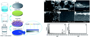

image file: c4ra08884k-p1.tif

Zee Ying Yeo

Zee Ying Yeo obtained first class honors in chemical engineering from Monash University, Malaysia, in 2009. Her inquisitiveness on membranes for gas separations has led her to further pursuing a Ph.D. in the synthesis of inorganic membranes. She is currently working on her doctoral thesis under the supervision of Dr Siang-Piao Chai on both zeolite and metal organic framework membranes for carbon dioxide and methane gas separations.

image file: c4ra08884k-p2.tif

Siang-Piao Chai

Dr Siang-Piao Chai obtained his bachelor of chemical engineering and Ph.D. from Universiti Sains, Malaysia, in 2008. He is currently a senior lecturer at the School of Chemical Engineering, Monash University, Malaysia. His main research interests focus on catalysis and reaction engineering, separation processes, nanoscience and nanotechnology.

image file: c4ra08884k-p3.tif

Peng Wei Zhu

Dr Peng-Wei Zhu obtained his bachelor of chemical engineering from Zhejiang University, China, in 1982 and his Ph.D. in chemistry from the Research School of Chemistry (Solid Molecular Chemistry), Australian National University, in 1994. His main research interests focus on functional colloids, surfactants and emulsions, stimuli responsive/functional materials, interfacial conformations and relevant phenomena, non-equilibrium and relaxations at surfaces/interfaces.

image file: c4ra08884k-p4.tif

Abdul Rahman Mohamed

Prof. Dr Abdul Rahman Mohamed obtained his bachelor of chemical engineering at the University of Southern California, USA, and his Ph.D. at the University of New Hampshire, USA. He is currently a professor at the School of Chemical Engineering and director at the Centre of Engineering Excellence, Universiti Sains, Malaysia. His research interests focus on reaction engineering and catalysis, air pollution and wastewater control engineering, fuel technology, and nanotechnology.


1. Introduction

In the past two decades, the synthesis of metal organic frameworks (MOFs) has attracted tremendous attention due to its plausible potential to obtain exceptionally interesting structures for applications in various fields related to porous materials, including carbon capture and storage,1–5 separation applications,6–11 and catalysis,12–17 depending on the pore size and shape as well as the host–guest interactions involved.18 Several excellent reviews published on MOFs could be found in the literature.19–25 Membrane gas separation is principally based on the differences in the diffusion rates of gas molecules within the membrane materials, where its separation performance was determined by the sizes of the gas molecules and microstructure of the membrane. The separation performance of a membrane is usually described by both permeability and selectivity. The permeability approximates the transport rate of species through the membrane, whereas selectivity assesses the capability of the membrane to separate the components of a mixture.

Membrane-based separations offer great potential in terms of their energy efficiency, resulting in less investment expense as compared to other competing technologies such as pressure swing adsorption and cryogenic distillation.26 The current market for membrane gas separation largely depends on polymeric membranes due to the fact that they have distinct advantages such as low production costs and high permeation fluxes.27,28 Permeation technologies based on conventional polymeric membranes have also been developed in the industry, including nitrogen production and hydrogen recovery.29 Nonetheless, the inherent challenges of polymeric membranes have generally limited them to the separation of non-condensable gases (such as CO2/CH4, H2/N2), where the harsh operating conditions to which these polymeric membranes will be exposed often result in a plasticization effect.30 On the other hand, zeolite molecular sieves have been investigated in terms of their application in membrane separations due to their well-defined regular pore structure with high thermal and chemical stability. The uniform pore size determined by their crystallographic structure makes zeolite membranes attractive for achieving high selectivity due to the molecular sieving effect. Regardless of these advantages, inorganic membranes have not found major industrial applications in gas separation except in the de-watering of bio-ethanol by steam permeation using supported zeolite LTA (Linde-type-A) membranes.31 Apart from its high production costs, the formation of nonstructural pores in real zeolite membranes is another issue that leads to difficulties in scaling up.30,31 Nonetheless, these zeolite membranes continue to attract a great deal of attention due to their excellent separation performance. Several zeolite membranes (such as DDR and T-type) have demonstrated very high CO2/CH4 selectivity, as observed in selected publications.32–34 Mixed-matrix membranes with porous or nonporous fillers deposited into polymeric membranes could enhance their permeability and selectivity. These hybrid membranes could combine the advantages of both phases: the superior gas transport properties of molecular sieves (high selectivity of the filler phase) with desirable mechanical properties, together with the low cost and good processability of the base polymers.35,36 Although mixed-matrix membranes have shown to be successful and promising,37–40 the main challenges often encountered are the void spaces between the inorganic filler (such as zeolites) and the polymer base, which allows gas molecules to channel through and results in a deteriorated selectivity. However, with MOFs (metal ions/clusters and organic ligands) appearing as inorganic–organic solids, they are expected to demonstrate better compatibility with polymers, due to the improved affinity of the MOF linkers with the polymer chains, resulting in mixed-matrix membranes with lower degrees of defects.37,41 For instance, Sorribas et al.42 prepared mixed-matrix membranes that were composed of silica-ZIF-8 core shell spheres in a polysulfone matrix for CO2 and CH4 separation. In addition, Hsieh et al.43 synthesized “breathing” MIL-53 into Matrimid®, forming mixed-matrix membranes. Interestingly, they found that the reversible change of an open-pore to closed-pore framework (breathing effect) of the MIL-53 was stabilized when embedded into the polymer matrix, suggesting that the breathing framework can be controlled with the restrictive effect in the polymer matrix.

Despite the devoted efforts and research progress made with different materials such as membranes for gas separation, challenges still remain, including inadequate selectivity and low permeability. MOF, distinguished by their high potential for specific functionalization allowing for the tuning of adsorptive interaction and the control of pore size via functional groups, are seen as an exciting candidate for gas separation as membrane materials.44,45 Obviously, membranes fabricated by materials with uniform pore sizes are much more preferable due to pore-size distribution, which plays a crucial role in separation performance. Despite being the subject of research for many years, the applications of zeolite membranes are still impeded by a limited choice of structure types (pore sizes) and difficulty in scaling up due to the formation of defects. MOFs, similar to zeolites, possess properties such as well-defined pore sizes and shapes that seem promising for advanced membranes. In the context of this review, we will discuss the continuous film of MOFs membranes and significant advances on the fabrication methods on these membranes, as well as their gas transport properties.

2. Fabrication of MOF membranes via in situ and secondary growth

Continuous and inter-grown MOF membranes are potential candidates for practical gas separation applications. Several techniques have been described in the literature to synthesize MOF membranes, including in situ synthesis and secondary (seeded) growth. There are several other techniques that have been reported for the synthesis of MOFs thin films, including self-assembled monolayers (SAMS),46–48 layer-by-layer deposition,49–52 colloidal deposition approach,53 and electrochemical deposition of MOF films.54–57 The attention of interested readers in these MOF thin films' syntheses could be directed to these articles.24,46–60

In situ involves only one step synthesis for fabricating membranes but does not offer the microstructure control and substrate independence of secondary (seeded) growth. This technique relies on the direct immersion of supports in precursor solutions containing both metal salts and linkers. Implementation of conventional or microwave heating will generate nucleation sites on the supports, leading to the growth of crystals on the substrate. This method has been observed to be difficult for the preparation of continuous films on bare substrates due to poor heterogeneous nucleation. Therefore, some researchers have reported chemical modifications on the supports in order to obtain high quality MOF membranes. The most important step of secondary (seeded) growth is the seed crystals' attachment to the support, followed by the immersion of the seeded support in the precursor solution of the particular MOF, in which membranes are produced in a procedure similar to in situ growth. With the existence of nuclei on the support surface, the influence of the support's surface chemistry is mostly eliminated. In many cases, secondary growth is preferably adopted to prepare membranes because the limitation of in situ growth will lead to poor coverage of crystallites on bare substrates.

2.1. In situ synthesis

In situ synthesis of MOFs membranes could be further branched into non-modified and modified substrates. Surface-modified substrates for the synthesis of MOFs membranes are further discussed and elaborated upon in Section 3.1. On the other hand, only several MOFs membranes have demonstrated in situ growth using non-modified substrates.61–63 ZIF-8, under the family of ZIFs, possesses high chemical and thermal stability with a sodalite-type structure with a narrow pore aperture of 0.34 nm, is thus highly attractive for membrane-based applications. For instance, Bux et al.61 employed titania disc support for the preparation of a ZIF-8 membrane with a thickness of ∼30 nm, achieving H2–CH4 selectivity of 11.2, thereby proving the ZIF-8 membrane fabricated was dense and free of cracking.

Another popular MOF, known as MOF-5, was prepared by Liu et al.63 on porous α-alumina substrate via in situ synthesis. The permeation data for H2, CH4, N2, CO2, and SF6 gases exhibited gas transport behaviour consistent with a Knudsen-type diffusion mechanism. This gas transport behaviour observed was specifically derived from the structural features of the framework with their MOF-5 pore size distribution centred around 1.56 nm. Herein, their large channel dimensions within the MOF-5 membrane were postulated to lead to lower contributions of gas molecule collisions with the pore walls, resulting in the Knudsen behaviour mechanism. However, it is also important to note that inter-crystalline boundary defects will contribute significantly to the overall transport mechanism via diffusion of the gas molecules, although such macroscopic defects were not observed in their scanning electron microscopy images.

Furthermore, Cao et al.64 prepared a Cu-BTC membrane on a novel potassium hexatitanate (K2Ti6O13) support where this support can adsorb Cu2+ in a moderate acid environment, which is more suitable for the growth of Cu2+ containing MOF membranes. The supports were treated in KOH solution to increase the concentration of free hydroxyl groups on the support surface, leading to more connection nodes for Cu-BTC growth. The Cu-BTC membrane displayed He/CO2 selectivity of 3.4 with He permeance of 1.4 × 10⁻⁶ mol m−2 s−1 Pa−1.

The adherence of both the MOF layer and substrate plays an important role for the growth of MOFs membranes. It is generally easier for the growth of MOFs on the polymer surface as their organic linkers have higher affinity towards the polymer surface. For example, Ben et al.65 prepared a free standing HKUST-1 membrane for gas separations, initially utilizing a polymer substrate. As shown in Fig. 1, their procedure involves spin coating of PMMA(poly(methyl-methacrylate)) onto a silica wafer, followed by reaction with sulfuric acid to hydrolyze the external PMMA into PMAA(poly(methacrylic-acid)). Then, the PMMA–PMAA–silica substrate was introduced into the HKUST-1 precursor at 120 °C for three days for membrane formation. Further immersion of the resultant membrane in chloroform could dissolve the PMMA–PMAA thin film and render the HKUST-1 membrane to be free standing. Their H2/N2, H2–CH4, and H2–CO2 equimolar gas permeation achieved a separation factor of 8.9, 11.2, and 9.3, respectively, at 25 °C and 1 bar.


image file: c4ra08884k-f1.tif
Fig. 1 Left side: Schematic illustration of the preparation of a free-standing HKUST-1 membrane. Right side: SEM images of the free-standing HKUST-1 microporous membrane: (a) top surface, (b) bottom surface, (c) cross-section; and SEM images of the PMMA–PMAA-supported HKUST-1 microporous membrane: (d) top surface, (e) bottom surface, and (f) cross-section. EDS of a cross-section of PMMA–PMAA-supported HKUST-1 membrane: (g) MOF layer and (h) polymer layer.

Consequently, Yao et al.62 developed a contra-diffusion method to prepare ZIF-8 films on both sides of a nylon substrate separating both zinc nitrate and 2-methylimidazole solutions, in which crystallization occurs on the membrane surfaces through solution contra-diffusion, as shown in Fig. 2. Continuous film of ZIF-8 was successfully fabricated on the zinc nitrate side of the nylon substrate with a thickness of up to ∼16 μm. Their sample exhibited H2/N2 selectivity of ∼4.3 with H2 permeance of 1.97 × 10⁻⁶ mol m−2 s−1 Pa−1, which further confirmed that the ZIF-8 films were continuous and compact. On the other hand, Hara et al.66 demonstrated that inter-crystalline defects can be reduced by applying a counter-diffusion method for the preparation of the Cu-BTC membrane. Based on the concept of reactant solutions supplied from the opposing sides of the support, reaction will occur within the pores until the MOF layer is “plugged,” which eliminates inter-crystalline defects. Their Cu-BTC membrane shows increased H2 selectivity and lower permeance with increasing preparation times, leading to an ideal H2–CH4 selectivity of 153. Recently, the same group of researchers67 synthesized ZIF-8 by applying the counter-diffusion method, displayed ideal separation factors for H2/C3H8 and C3H6/C3H8 of 2000 and 59, respectively, with H2 and C3H6 permeances of 9.1 × 10⁻⁸ and 2.5 × 10⁻⁹ mol m−2 s−1 Pa−1, respectively. The large separation factor of H2/C3H8 clearly evidenced the potential separation ability of ZIF-8.


image file: c4ra08884k-f2.tif
Fig. 2 (a) Diffusion cell for ZIF-8 film preparation and (b) the schematic illustration of ZIF-8 films preparation on both sides of the nylon support via contra-diffusion of Zn2+ and 2-methyl-imidazole through the pores of the nylon support (Left). SEM image of the cross-section ZIF-8 film prepared at room temperature for 72 h at the zinc nitrate solution side (Right).62

Interestingly, Shah et al.68 developed a new synthesis protocol called “rapid thermal deposition (RTD)” based on the concept of evaporation-induced crystallization performed at elevated temperature. In this method, α-alumina porous supports are initially soaked with MOF precursor solution and subjected to 180 °C, in which solvent evaporation will drive the flow of the precursor solution from inside the supports to outside where crystallization occurs. RTD was applied to both HKUST-1 and ZIF-8 membranes. The prepared HKUST-1 membranes showed very high (∼600) H2/SF6 ideal selectivity, whereas ZIF-8 membranes exhibited an average C3H6/C3H8 selectivity of ∼30.

2.2. Secondary (seeded) growth

Despite several new strategies that have been employed to deposit seed layers on the substrate prior to secondary growth, Venna et al.69 synthesized ZIF-8 membranes by the conventional method of rubbing seeding on tubular α-alumina supports. Their ZIF-8 membranes (∼5–9 μm thickness) exhibited unprecedented CO2 permeances of ∼2.4 × 10⁻⁵ mol m−2 s−1 Pa−1 with CO2/CH4 selectivities in the range of 4–7. It was unexpected to see the ZIF-8 membrane displaying a moderate selectivity for CO2 over CH4 despite the pore diameter of ZIF-8 (0.34 nm) falling in between the kinetic diameter of CO2 (0.33 nm) and CH4 (0.38 nm). In spite of the fact that the pore window of ZIF-8 is estimated to be 0.34 nm from crystallographic data, several literatures70–72 have reported that the ZIF-8 framework structure is in fact more flexible and even large molecules like CH4 (with a critical diameter of 0.38 nm) can easily permeate through the pore network. In line with their moderate selectivity, it is important that high CO2 selectivity at this stage of MOFs research could be achieved for any potential industrial applicability.

Nan et al.73 applied a step-by-step seeding procedure to obtain a uniform seed layer on the alumina support, followed by secondary growth to the formation of the HKUST-1 membrane. The single gas permeation of the step-by-step HKUST-1 membranes has resulted in ideal selectivities of 2.9, 3.7, and 5.1 for H2–CH4, H2/N2, and H2–CO2, respectively, approaching the corresponding Knudsen selectivities. Initially, an in situ hydrothermal growth experiment for the formation of HKUST-1 membrane has been constructed; however, the discontinuous HKUST-1 membranes indicated that HKUST-1 crystals were prone to grow in the solution rather than on the bare support.

On the other hand, reactive seeding involves bonding the membrane support with its required precursor to form the seed layer for further secondary hydrothermal synthesis of MOFs membrane synthesis. It can also be carried out using in situ growth to generate seeds on the substrate. As reported by Hu et al.,74 preparation of the MIL-53 membrane on the alumina support was performed (Fig. 3). In this procedure, α-alumina support was seeded with 1,4-benzenedicarboxylic acid (H2BDC) under a mild hydrothermal method (Fig. 3a), followed by secondary growth with a precursor containing both Al(NO3)3·9H2O and H2BDC. Fig. 3c and d show the surface of a highly inter-grown MIL-53 membrane synthesized and cross-sectional area of well-bonded MIL-53 membrane on the support, respectively. In a similar manner, Nan et al.75 also developed reactive seeding method for the synthesis of MIL-53 and MIL-96 membranes. They investigated the interactions between the support and organic precursor in which a two-step mechanism of a reactive seeding method was proposed. Based on the mechanism, the alpha alumina support was initially reacted with H2O at 210 °C to produce γ-AlO(OH), then with γ-AlO(OH) interacted with H3(btc) to form MIL-96 seeds.


image file: c4ra08884k-f3.tif
Fig. 3 Schematic showing the preparation of MIL-53 membrane on alumina support via the reactive seeding method (Left). SEM images of (a) MIL-53 seed layer (b), MIL-53 powders, (c) MIL-53 membrane surface and (d) cross-section (Right).74

Herein, a counter-diffusion method involving the seeding process has been demonstrated by Kwon et al.76 for the synthesis of a ZIF-8 membrane, shown in Fig. 4, in which the porous α-alumina support is soaked in a metal precursor followed by rapid solvothermal reaction in a ligand solution. During the reaction, the concentration gradients facilitate metal ions and ligands to diffuse from the support into the solution and vice versa. The authors claimed that their shorter reaction time method is better than the typical counter-diffusion, which involves longer diffusion rates, where they revealed ZIF-8 membrane thickness of only 1.5 μm. It is inspiring that their propylene/propane (C3H6/C3H8) separation of ZIF-8 demonstrated an excellent separation factor of ∼55, even only synthesized for 30 minutes. The author concluded that the counter-diffusion method enabled the defective membranes to be identified and healed without disassembling the membrane modules.


image file: c4ra08884k-f4.tif
Fig. 4 Schematic illustration of ZIF-8 membrane synthesized via the counter-diffusion method: (1) porous alumina support saturated with metal precursor solution (Zn2+) placed in a ligand solution (m-Im) containing sodium formate; (2) diffusion of metal ions and ligand molecules causing the formation of a “reaction zone” at the interface; and (3) the rapid heterogeneous nucleation/crystal growth at the interface leads to well inter-grown ZIF-8 membrane.76

3. Challenges associated with MOFs membrane fabrication

The successful synthesis of MOFs with sufficient quality for gas separation remain as a challenging task due to the inherent weak coordination bonds of MOFs and its unfavourable heterogeneous nucleation. These weak properties of MOFs have called for more research efforts in order to successfully synthesize better quality MOFs membranes. With MOFs emerging as a new nanoporous material, expectations arise on whether MOFs could overcome all of the challenges and barriers characterized by other membrane materials. The general challenges associated with the fabrication of MOFs membrane generally include (1) poor interaction with the substrate, (2) moisture instability (water replacing carboxylates), and (3) easily induced macroscopic cracks. Although these challenges represent a common difficulty in MOFs membrane fabrication, they do not say the same for all kinds of MOFs membranes.

3.1. Poor interaction of MOFs with substrate

Several MOFs such as MOF-5[thin space (1/6-em)]77 have been reported to have insufficient interfacial interaction with substrates for the synthesis of MOFs membranes.77–83 Researchers have reported various techniques to improve the MOFs crystal adhesion to the membrane support for membrane fabrication. They include support modification with chemicals to enhance the covalent linking between MOFs and support, the use of polymer binders and graphite coatings to improve the secondary binding via hydrogen bonding, or by having pre-attached seed crystals to the support so that crystallization growth will be more substrate independent.

For instance, Xie et al.81 deposited APTES-functionalized α-Al2O3 particles onto coarse macroporous support for the formation of the ZIF-8 membrane. Apart from pore-structure modification of the coarse macroporous support, the APTES-modified α-Al2O3 served to promote the high density of heterogeneous nucleation sites to produce thin and defect-free ZIF-8 membrane. Inspired by Huang et al.,80,84 APTES grafted on TiO2 or Al2O3 support can promote the heterogeneous nucleation of ZIF-22 (pore size of 0.30 nm) and ZIF-90 (pore size of 0.35 nm) to form dense membranes. As evaluated in gas permeation experiments, the ZIF-8 membrane of Xie et al.81 exhibited remarkably high H2 permeance of 5.73 × 10⁵ mol m−2 s−1 Pa−1 with H2/N2 and H2–CO2 selectivities of 15.4 and 17.0, respectively. Moreover, Huang et al.80 reasoned that the 3-aminopropylsilyl groups of APTES can coordinate to the free Zn2+ centers and bind the growing nanocrystals to form the covalent linker between the growing ZIF-22 layer and the support. The ideal separation performance of ZIF-22, determined by the ratio of single component permeances, displayed H2–CO2, H2/O2, H2/N2, and H2–CH4 selectivities of 8.5, 7.2, 7.1, and 6.7, respectively. In addition, the binary separation of H2–CO2, H2/O2, H2/N2, and H2–CH4 also displayed selectivities of 7.2, 6.4, 6.4 and 5.2, respectively, which exceed the corresponding Knudsen constants.

Moreover, in a recent paper reported by Huang et al.,85 they reported the preparation of a highly permselective ZIF-8 membrane supported on polydopamine (PDA)-functionalized stainless steel nets (SSN). The high void volume of the SSN with thread woven of 25 μm thick and an aperture of 30 × 30 μm is expected to boost the gas permeances through the membrane. With similar ideology, they promote the nucleation and growth of well inter-grown ZIF-8 membranes on SSN by functionalization with PDA due to its strong adhesive ability via the formation of strong noncovalent and covalent bonds with surface hydroxy groups. The schematic diagram for the preparation of PDA-modified SSN supported the ZIF-8 layer was shown in Fig. 5. Due to the adhesive ability of PDA, a well inter-grown and highly selective ZIF-8 membrane was prepared and strongly anchored to the SSN support (Fig. 5c and d) as compared to the poorly inter-grown ZIF-8 layer with obvious intercrystalline gaps as observed in a non-modified SSM (Fig. 5a and b). Their binary separation at 100 °C and 1 bar demonstrated H2–CO2, H2/N2, H2–CH4 and H2/C3H8 separation factors of 8.1, 15.0, 23.2 and 329.7, respectively, far beyond Knudsen coefficients. Their displayed H2 permeance of >2.1 × 10⁻⁵ mol m−2 s−1 Pa−1 is by far the highest H2 permeance in ZIF-8 membranes to date. These results demonstrated the ZIF-8 capabilities of separating H2 from other gases, especially C3H8.


image file: c4ra08884k-f5.tif
Fig. 5 Schematic illustration of the ZIF-8 membrane preparation on PDA-functionalized SSN (Top). FESEM images of the upper side (a) and down side (b) of the ZIF-8 layer prepared for 24 h on non-modified SSN, FESEM images of upper side (c) and down side (d) of the of ZIF-8 membrane prepared for 24 h on PDA-functionalized SSN (Bottom).85

Guo et al.86 introduced the “twin copper source” growth method for the preparation of the Cu3(BTC)2 membrane. A copper net support of 400 mesh was oxidised, followed by placing it into the reaction solution for Cu3(BTC)2 film growth in a teflon-lined autoclave. By oxidizing the copper net before the hydrothermal synthesis, homogeneous nucleation sites are formed for continuous film growth. The ions of Cu2+ both on the copper net and in the reaction solution acted as a metal source for crystal growth. Subjected to gas permeation tests, their Cu3(BTC)2 membrane displayed binary separation factors of 7.04, 6.84, and 5.92 for H2/N2, H2–CO2, and H2–CH4, respectively, with H2 permeance of 1.07 × 10⁻¹ mol m−2 s−1 Pa−1; and ideal separation factors of 4.60, 4.52, and 7.8 for H2/N2, H2–CO2, and H2–CH4, respectively, with H2 permeance of 1.27 × 10⁻¹ mol m−2 s−1 Pa−1. This separation performance is far beyond the Knudsen diffusion behaviour, with H2 permeance higher than other gases, indicating that this membrane has a high preference for the selectivity of H2. In addition, the binary separation factors of H2/N2 and H2–CO2 are both higher than its ideal separation factor, whereas ideal separation factor for H2–CH4 is higher than its binary separation factor. This could be due to the fact that the slower diffusing CH4 with stronger sorption will prohibit the diffusion of faster diffusing H2 in the mixture. Although it sounds interesting for the copper net to represent both as physical supports, as well as the copper source for the membrane crystallization, its inherent free-standing characteristics may induce mechanical stability in long-term practical applications.

The thermal seeding technique, by introducing the seed crystals together with both organic ligands and species in the seed suspensions for seeding at elevated temperatures, was found to be an interesting approach to strongly bind the seed crystals to the porous supports. Guerrero et al.79 reported the fabrication of continuous HKUST-1 membranes via the thermal seeding technique. It was hypothesized that the un-reacted ligands and Cu complexes served as binders for the binding between the HKUST-1 seed crystals and alumina support.79 The maximum ideal selectivity of the HKUST-1 membrane attained H2/N2, H2–CH4 and H2–CO2 selectivities of 7.5, 5.7, and 5.1, respectively. On the other hand, McCarthy et al.78 employed a support modification process for the synthesis of the ZIF-8 membrane. Although similar to the thermal seeding technique reported by Guerrero et al.,79 the significant difference is the usage of the organic linker solution instead of the seed crystal solution. They observed that solvothermal synthesis without surface modification of the support does not produce ZIF-8 films. Firstly, this phenomenon indicated that heterogeneous nucleation is not favoured on unmodified α-alumina due to a lack of interaction between ZIF-8 and porous α-alumina support. Secondly, the high-temperature surface modification process was expected to ensure that linkers are attached to the support surface via an activated process, which forms covalent bonding of Al–N. Their ZIF-8 membrane exhibited molecular sieving behaviour with ideal selectivities of 11.6 and 13 for H2/N2 and H2–CH4, respectively.

Because continuous films are difficult to form directly on bare alumina supports, anchoring seed crystals to the surface of the support by the treatment of the substrate with polyethyleneimine coating or chitosan binder has been recommended. Ranjan et al.87 synthesized MMOF membranes via seeded growth on a surface-modified α-alumina support. The α-alumina support was modified using polyethyleneimine (PEI) for the enhanced attachment of seeds via hydrogen bonding. The membrane exhibits moderate selectivity of H2/N2 and H2–CO2 both around ∼4.0 at room temperature. However, increasing the temperature to around 190 °C, the ideal selectivity of H2/N2 reaches to ∼23. Li et al.88 also performed secondary seeded growth in synthesizing ZIF-7 membranes using PEI as a binder, as shown in Fig. 6. It could be clearly seen in Fig. 6b and c that the ZIF-7 layer was deposited on the support with a thickness of just ∼1.5 μm, representing one of the thinnest MOF-based membranes reported to date. PEI was expected not only to stabilize the seed particles in the suspension but also to enhance the linkage between the seeds and the support through hydrogen bonding interactions. The ZIF-7 membrane exhibits a pore diameter of approximately 0.3 nm, achieving H2–CO2 ideal selectivity and separation factors of 6.7 and 6.5, respectively, whereas for 1[thin space (1/6-em)]:[thin space (1/6-em)]1 binary mixtures, their H2/N2 and H2–CH4 separation factors were found to be 7.7 and 5.9, respectively (at 200 °C and 1 bar). Similarly, Zhou et al.89 used chitosan as a binder to improve the binding force between Cu3(BTC)2 seeds and hollow ceramic fiber (HCF) porous support due to its abundance in amino and hydroxyl groups. Chitosan played a key role in strengthening the mutual interaction between the support and Cu3(BTC)2 crystals in the preparation of the membrane. The as-prepared membrane shows high H2 single gas permeance of 7.25 × 10⁻⁸ mol m−2 s−1 Pa−1 and binary permeances in the range of 3.23–4.10 × 10⁻⁸ mol m−2 s−1 Pa−1. Moreover, their membrane shows separation factors of 8.66, 13.56, and 6.19 for H2/N2, H2–CO2, and H2–CH4 gas mixtures, respectively.


image file: c4ra08884k-f6.tif
Fig. 6 (a) Surface and (b) cross-section SEM images of ZIF-7 membrane. (c) Cross-section SEM image of the ZIF-7 membrane (left) and the same image overlaid with an EDX mapping (right). In the EDX mapping, light orange and cyan represent Zn and Ti, respectively, the results clearly show the clean formation of the ZIF-7 layer on the alumina support.88

The coatings of membrane substrates could also be performed in order to enhance the overall formation of the MOFs membranes. Yoo et al.90 reported a microwave-induced thermal deposition method to prepare MOF-5 crystals on different porous substrates. MOF-5 were grown on three different substrates (bare anodized Al2O3, carbon coated Al2O3, and graphite coated Al2O3) prepared under 30 seconds of microwave irradiation. The kinetics of heterogeneous nucleation and the growth of MOF-5 crystals are enhanced when thin conductive layers such as carbon or graphite are coated as compared to bare substrates. Upon close examination of the morphology of the film, graphite-coated MOF-5 membranes show more densely packed MOF-5 crystals as compared to carbon-coated and bare substrate membranes. The smaller size and higher density of MOF-5 crystals formation on the graphite-coated substrate was explained by rapid formation of more nuclei on the graphite surface under microwaves, followed by their mass transfer-limited growth.

H. K. Jeong's group78 initially prepared the ZIF-8 membrane through in situ synthesis using 2-methylimidazole modified support with the resultant 20 μm membrane thickness exhibiting a H2 permeance of ∼1.8 × 10⁻⁷ mol m−2 s−1 Pa−1. Furthermore, they have innovated new methods for preparing ZIF-8 membranes, which include rapid thermal deposition68 and an in situ counter-diffusion method.76 The rapid thermal deposition preparation method resulted in 5–20 μm membrane thicknesses with the highest propylene binary permeance of 8.1 × 10⁻⁹ mol m−2 s−1 Pa−1 with a propylene/propane binary selectivity of 41. On the other hand, the in situ counter-diffusion method has produced ZIF-8 membrane with a thickness of ∼2 μm, demonstrating binary propylene permeance of 2.3 × 10⁻⁸ mol m−2 s−1 Pa−1 with separation factor of 50. Although the rapid thermal deposition method can prepare the ZIF-8 membrane in a short period of time (∼10 minutes), one of the disadvantages as compared to the counter-diffusion method is that it is often difficult to identify and heal the defect of the membrane. On the other hand, the counter-diffusion method enables the defect of the membranes to be identified and healed without disassembling the membrane modules.

J. Caro's group61,85,91 has prepared ZIF-8 membranes utilizing different approaches, some as previously mentioned in this manuscript. For example, in situ preparation on titania support,61 secondary (seeded) growth using polyethyleneimine as the coupling agent,91 and the synthesis of ZIF-8 on support-modified poly-dopamine-functionalized stainless steel nets.85 Although these ZIF-8 membranes have been successfully prepared using conventional supports and show promising separation selectivity, they have not resulted in high permeability when compared to modified supports such as stainless steel nets. This is most probably due to the large flow resistance of gas transport through the conventional thick ceramic supports (∼1 to 2 mm). As reported, both membranes synthesized on conventional supports exhibited H2 permeance of ∼10−8 mol m−2 s−1 Pa−1, whereas stainless steel net support demonstrated H2 permeance of ∼10−5 mol m−2 s−1 Pa−1.

3.2. Moisture instability and easily induced cracks

Generally, metal–ligand coordination bonds of MOFs are not as strong as the Si–O covalent bonds in zeolite membranes; thus, moisture instability and cracks are more likely to form. One of the reasons for crack formation is attributed to the stress on the film due to the mismatch between both the thermal expansion coefficient of the support and the MOFs membrane. Guerrero et al.79 prevented cracking in their HKUST-1 membrane by slowly cooling down the autoclaves from 120 °C to 60 °C at 1 °C min−1 and then naturally to room temperature. The membranes need to be dried in order for the activation of its channels. However, attempted drying (activation of pores) at room temperature or at elevated temperatures clearly revealed cracking. Because the magnitude of the capillary stress in the membranes is proportional to the rate of evaporation, they evaporated the water at 40 °C under nearly saturated conditions, thereby completely eliminating the cracks.

Several attempts have been performed by Dong et al.92 to eliminate the micro-cracks of their ZIF-78 membrane. For instance, despite immersing the membrane in fresh methanol for 12 hours followed by drying at 60 °C under vacuum, micro-cracks were still observed, which were likely due to the rapid methanol drying process. They have also performed drying at 40 °C under a saturated methanol environment for three days, which does not result in optimistic molecular sieve behaviour. The author discussed that with pure methanol used for solvent exchange for DMF removal, diffusion of DMF will be too rapid due to the high concentration gradient. Therefore, they prepared a series of methanol–DMF mixtures with 25%, 50%, 75% and 100% of methanol concentrations. As shown in Fig. 7, they immerse the ZIF-78 membrane in these solutions in turn for solvent exchange followed by a slow evaporation through the methanol drying process. The as-prepared ZIF-78 membrane for further gas separation has achieved H2–CO2 ideal and binary selectivity of 11.0 and 9.5, respectively.


image file: c4ra08884k-f7.tif
Fig. 7 Schematic diagram of the activating process of the ZIF-78 membrane.92

Post-synthetic modifications (PSM) can also be implemented to improve MOFs moisture stability. Nguyen and Cohen93 have demonstrated that hydrophobic properties can be incorporated within a MOF. Amine-containing MOFs can readily undergo PSM to form amide-functionalized MOFs. The hypothesis was that the introduction of hydrophobic alkyl chains could improve moisture resistance and change the physical properties (i.e. hydrophobicity) of the MOFs. Through the integration of medium-to-long hydrophobic alkyl groups within IRMOF-3, the moisture-sensitive IRMOF-3 could be shielded from moisture by changing its property to hydrophobic. Within the same study, a more chemically robust MOF, MIL-53(Al)-NH2, was examined to check how the same functional groups would affect its properties. It was found that MIL-53(Al) modified with longer alkyl substituents appear to possess super-hydrophobic properties with contact angles greater than 150°.

Conversely, Yoo et al.94 improved the crack resistance and moisture stability of IRMOF-3 via surfactant-assisted drying and post-synthetic modifying method. As illustrated in Fig. 8, IRMOF-1 seeds were initially prepared on graphite-coated alumina via a microwave-assisted seeding, followed by the formation of IRMOF-3 membranes. IRMOF-3-AM6 membranes were prepared by post-synthetically modifying the IRMOF-3 membranes with heptanoic anhydride (AM6). First, they studied two different non-ionic surfactants, P123 and Span 80, for the elimination of cracks. Cracks are substantially reduced when P123 was added to the final drying stage, whereas the addition of Span 80 exhibited no macroscopic crack. It was hypothesized that smaller hydrophilic head groups of Span 80 can interact favourably with the surface of IRMOF-3 as compared to bulkier hydrophilic groups of P123, resulting in the improved performance of Span 80 as compared to P123. IRMOF-3 has switched from hydrophilic to hydrophobic after being dried in the presence of Span 80. Hydrophobic MOFs with better moisture stability will repel water molecules, subsequently preventing water molecules from displacing its carboxylic groups. Following the study of surfactant-assisted drying, IRMOF-3 was post-synthetically modified with AM6 to change its pore size and property of the membrane. The effective pore size has decreased, and the surface property of the post-synthetically modified IRMOF-3-AM6 was changed with ∼91% of amine groups converted to amides based on TGA characterizations. After modification with hydrophobic anhydrides, the moisture stability of IRMOF-3 was drastically improved.


image file: c4ra08884k-f8.tif
Fig. 8 Schematic illustration of the fabrication of crack-free MOF membranes (IRMOF-3 and IRMOF-3-AM6 membranes) using a surfactant-assisted drying process (Left). SEM images of IRMOF-3 membranes after drying (a) without surfactant, (b) with a triblock copolymer, P-123, and (c) Span 80. The cross-sectional view (d) is from the membrane dried in the presence of Span 80 with a thickness of ∼10 μm (Right).94

Layer-by-layer (LBL) growth of MOFs thin films involves repeated cycles of immersion of a membrane substrate in solutions with both metal salts and organic linkers. The substrate will be rinsed with solvent to remove the un-reacted components in between their deposition steps. Herein, Lee et al.95 synthesized Ni-MOF-74 membranes via a combined layer-by-layer seeding and secondary growth technique and described their procedure in preventing crack formation of MOF membranes. They showed that an optimum concentration of solution (8.0 mmol Ni(CH3COO)2 and 4.0 mmol 2,5-dihydroxyterephthalic acid) was needed in order to obtain a crack-free Ni-MOF-74 membrane together with four alternating immersion cycles. They concluded that a more concentrated solution provides sufficient nutrition for the growth of crystals to help achieve crack-free Ni-MOF-74 membranes; however, a solution with excessively high concentration would also lead to the degradation of membrane performance. The single gas permeation test on the Ni-MOF-74 has resulted in H2/N2, H2–CO2, and H2–CH4 ideal selectivities of 3.1, 9.1, and 2.9, respectively. With CO2 permeance deviating from the linear relation, it can be ascribed to surface diffusion due to strong adsorption affinity of CO2 to the Ni-MOF-74 membrane. The detailed explanation for its adsorption affinity could be found in detail in the literature.95

4. Outlook and perspective

Due to the recentness of MOFs materials, their real potential for membrane gas separation, such as H2 separation, natural gas purification (CO2 separation over CH4), and CO2 reduction from flue gas, has not been fully explored. In order to evaluate these potential MOFs membranes for CO2 separation, numerous properties such as CO2 adsorption affinity, pore size and framework structure, and thermal and humidity stability need to be thoroughly investigated. ZIFs, a subclass of MOFs, with their proven unusual stability coupled with various ranges of pore sizes seem to have great potential for CO2 separation.96 However, the separation of gas molecules based on appropriate pore size is not as simple as it seems due to its framework structure flexibility, which is against the molecular sieving mechanism.22,61,88 For example, recent reported results of ZIF-7[thin space (1/6-em)]88 with a pore aperture of 0.30 nm designated that even large molecules such as CH4 (0.38 nm) are able to permeate through the membrane, indicating that it may be useful to pursue ZIFs with smaller apertures. On the other hand, Bux et al.91 stated that a sharp cut-off permeance has not been observed for ZIF membranes, due to the flexible nature of its framework. The author demonstrated only a sharp cut-off permeance of H2 and C3H8 with a ZIF-8 pore aperture of 0.34 nm, indicating that the large derivations of the experimental separation factors as compared to those predicted from rigid framework structure models were not all attributed to mass transfer through grain boundaries or defects. This is in contrast to those of zeolite membranes that exhibit “molecular sieving properties,” with substantial reduction in permeance for molecules with a kinetic diameter greater than its pore size.

MOFs membranes are still capped within research at the current stage, and the large scales of their applications are not yet ready to be envisioned with the existing commercial technology. Nonetheless, there are researchers working on the scalability of MOFs membranes.97–99 In particular, Brown et al.97 reported a route that could mainly overcome the limitation of the current synthesis process, a notable step towards accomplishing scalable MOF membranes. Their method involves combining two solvent interfacial approaches for positional control over ZIF-8 membrane formation on the polymeric hollow fibres, a micro-fluidic approach, for replenishing and recycling the reactants for membrane fabrication. Their continuous ZIF-8 membranes fabricated on poly(amine-imide) hollow fibres achieved the highest H2/C3H8 and C3H6/C3H8 separation factors of 370 and 12, respectively. Mao et al.98 prepared continuous HKUST-1 membranes by filtering copper nitrate through the PVDF hollow fibres, followed by immersing the PVDF hollow fibre in a container filled with trimesic acid with a regulating pump. A continuous HKUST-1 membrane with a thickness of 3 μm was obtained typically after ∼40 minutes. Their HKUST-1 membrane achieved H2–CO2, H2/N2, and H2–CH4 separation factors of 8.1, 6.5, and 5.4, respectively. On the other hand, Fan et al.99 adopted the electrospinning technology for seeding purposes. A high voltage will be applied to the metallic tip to draw the viscous solution into the fibres in which the macroporous SiO2 support will serve as the collector. With the advantage of this electrospinning technology, this method could be applied to various kinds of supports with potential for large-area processing. Despite the fact that researchers are working on the scalability of MOFs membranes, no firm conclusion on the scalability of MOFs membranes could be drawn until now. Therefore, more open ideas and promising results are needed in order to enable the research community to resolve this issue.

Furthermore, despite the development of MOFs membranes made over several years, MOFs still have further potential for improvement. Nonetheless, it is constructive to compare different types of MOFs membranes in terms of their gas separation performances. Tables 1 and 2 present the single gas permeation and selectivities of several gases on different MOFs membranes, respectively, showing attractively high permeances, although their permselectivity is still only relatively moderate.

Table 1 Summary of single gas permeances of MOFs membranes
MOF T (°C) Pore aperture (nm) Permeances (108 mol m−2 s−1 Pa−1) at 1 bar Ref.
H2 CO2 N2 O2 CO CH4 SF6 He C2H6 C3H6 C3H8
a Refers to ZIF-8 synthesized for 4 hours via a counter diffusion-based in situ method.b Refers to CO2 permeances dropped with time from 9.8 × 10⁻⁸ mol m−2 s−1 Pa−1 at 0.1 hour to 1.7 × 10⁻⁸ mol m−2 s−1 Pa−1, reaching equilibrium at 12 hours.c Refers to binary gas permeation measurement with 1[thin space (1/6-em)]:[thin space (1/6-em)]1 H2–CO2 mixture.d Refers to post-functionalized ZIF-90 with ethanolamine.e Refers to post-functionalized ZIF-90 with APTES ((3-Aminopropyl)triethoxysilane).f Refers to HKUST-1 thin film displaying permeances with a unit of 100 mol m−2 s−1 Pa−1 at 1 bar.
MOF-5 25 1.4 280 65 80 105 42 63
MOF-5 25 1.4 130 33 40 55 22 63
MOF-5 25 1.4 80 25 30 39 77
MOF-5 25 1.4 44 10 13 13 4.2 30 107
ZIF-8 25 0.34 2430 472 69
ZIF-8 25 0.34 1690 242 69
ZIF-8a 20 0.34 1.85 0.02 76
ZIF-8a 150 0.34 1.10 0.06 76
ZIF-8 25 0.34 17.5 4.5 2 5.5 2 78
ZIF-8 100 0.34 2660 302 173 108 6.01 85
ZIF-8b 25 0.34 99 1.7–9.8b 31 25 108
ZIF-8 25 0.34 35 15 9 8 7 1 0.07 109
ZIF-8 25 0.34 110 22 17.5 18 110
ZIF-8 25 0.34 17 3 111
ZIF-8 25 0.34 154 40 14 12 9 0.14 112
ZIF-8 25 0.34 2.0788 0.0546 113
ZIF-8 35 0.34 47.2 12.2 4.46 4.17 0.0291 19.1 114
ZIF-7 200 0.29 7.4 1.1 1.1 1.2   88
ZIF-7 220 0.29 4.55 0.35 0.22 0.31 115
ZIF-7c 25 0.29 45.7 4.77 116
ZIF-7c 150 0.29 30.5 1.67 116
ZIF-22 50 0.29 20 2.4 2.8 2.8 3 80
ZIF-69 25 0.44 6.5 2.5 1.1 1.7 0.5 117
ZIF-69 25 0.44 2.36 1.06 0.82 0.86 118
ZIF-90 200 0.35 25 3.5 2 1.7 84
ZIF-90 200 0.35 25 3 2 1.5 119
ZIF-90d 200 0.35 21 1.5 1.2 1.2 119
ZIF-90 225 0.35 31 3.75 2.0 1.0 ∼0.9 120
ZIF-90e 225 0.35 29.5 1.75 0.8 ∼0.3 ∼0.2 120
ZIF-95 325 0.37 246 7.04 22.7 16.1 3.69 106
HKUST-1 25 0.9 74.8 14.8 20 25.7 73
HKUST-1 25 0.9 200 50 50 80 79
HKUST-1 190 0.9 110 20 15 20 79
HKUST-1f 25 0.9 0.127 0.0281 0.0276 0.0163 86
HKUST-1 25 0.9 18 4 4 4 6 121
MMOF 25 0.32 1.8 0.4 0.4 1.4 87
MMOF 190 0.32 0.2 0.04 0.01 0.3 87
Bio-MOF-1 25 NA 119 46 122
Bio-MOF-13 22 0.32–0.64 310–406 82–131 123
Bio-MOF-14 22 0.16–0.40 416–455 118–141 123


Table 2 Summary of single gas selectivities of MOFs membranes
MOF T (°C) Pore aperture (nm) Permeances (108 mol m−2 s−1 Pa−1) at 1 bar Ref.
H2–CO2 H2/N2 H2/O2 H2/CO H2–CH4 H2/SF6 H2/He H2/C2H6 H2/C3H8 CO2/CH4 C3H6/C3H8
MOF-5 25 1.4 4.3 3.5 2.7 6.7 0.6 63
MOF-5 25 1.4 3.9 3.3 2.4 5.9 0.6 63
MOF-5 25 1.4 3.2 2.7 2.1 0.6 77
MOF-5 25 1.4 4.4 3.4 3.4 10.5 1.5 107
ZIF-8 25 0.34 5.1 69
ZIF-8 25 0.34 7.0 69
ZIF-8 20 0.34 92.5 76
ZIF-8 150 0.34 18.3 76
ZIF-8 25 0.34 3.9 8.8 3.2 8.8 2.3 78
ZIF-8 100 0.34 8.8 15.4 24.6 442.6 2.8 85
ZIF-8 25 0.34 10.1-58.2 3.2 4.0 108
ZIF-8 25 0.34 2.3 3.9 4.4 5.0 500.0 1.9 14.3 109
ZIF-8 25 0.34 5.0 6.3 6.1 1.2 110
ZIF-8 25 0.34 5.7 111
ZIF-8 25 0.34 3.9 11.0 12.8 17.1 1100.0 3.3 112
ZIF-8 25 0.34 38.1 113
ZIF-8 35 0.34 3.9 10.6 11.3 1622.0 2.5 2.9 114
ZIF-7 200 0.29 6.7 6.7 6.2 0.9 88
ZIF-7 220 0.29 13.0 20.7 14.7 1.1 115
ZIF-7 25 0.29 9.6   116
ZIF-7 150 0.29 18.3 116
ZIF-22 50 0.29 8.3 7.1 7.1 6.7 0.8 80
ZIF-69 25 0.44 2.6 5.9 3.8 13.0 1.5 117
ZIF-69 25 0.44 2.7 118
ZIF-90 200 0.35 7.1 12.5 14.7 2.1 84
ZIF-90 200 0.35 8.3 12.5 16.7 2.0 119
ZIF-90 200 0.35 14.0 17.5 17.5 1.3 119
ZIF-90 225 0.35 8.3 15.5 31.0 34.4 1.9 120
ZIF-90 225 0.35 16.9 36.9 98.3 147.5 2.2 120
ZIF-95 325 0.37 34.9 10.8 15.3 66.7 0.4 106
HKUST-1 25 0.9 5.1 3.7 2.9 0.6 73
HKUST-1 25 0.9 4.0 4.0 2.5 0.6 79
HKUST-1 190 0.9 5.5 7.3 5.5 1.0 79
HKUST-1 25 0.9 4.5 4.6 7.8 1.7 86
HKUST-1 25 0.9 4.5 4.5 4.5 3.0 0.7 121
MMOF 25 0.32 4.5 4.5 1.3 87
MMOF 190 0.32 5.0 20.0 0.7 87
Bio-MOF-1 25 NA 2.6 122
Bio-MOF-13 22 0.32–0.64 3.1–3.8 123
Bio-MOF-14 22 0.16–0.40 3.2–3.5 123


5. Conclusions

MOFs, the offspring of porous materials, are considered to be relatively new despite the research made over the past decade. Although several MOFs membranes have been synthesized by researchers,91,100–106 the permeability and selectivity of these membranes were not found to be outstandingly attractive. This could be due to the nature of MOFs with moderate selectivity, membrane defects caused by handling issues and the unfavourable orientation of crystals in the membrane. There is still considerable potential for improvement in the preparation of MOFs membranes, and the main concerns involve overcoming its easily cracked formation and improving its separation performance. Great care must be taken not only in the synthesis of MOFs membranes but also in the activation and characterization for having fair and unbiased membrane comparison. In the case of membrane separations, the development of MOFs membranes that are reproducible for scaling up is still a major issue in future research. Furthermore, the final curtain for MOFs membranes should not be a calculated selectivity using single-component gas permeances, but rather selectively capturing one component from the other contaminants in harsh and real operating environments (such as a hot flue gas stream). Further research would lead to stronger optimism that MOFs can overcome its intrinsic limitations.

Acknowledgements

We would like to thank the Ministry of Higher Education, Malaysia for the financial support through the Long term Research Grant Scheme (LRGS) (A/C number 2110226-113-00).

Notes and references

  1. A. M. Fracaroli, H. Furukawa, M. Suzuki, M. Dodd, S. Okajima, F. Gándara, J. A. Reimer and O. M. Yaghi, J. Am. Chem. Soc., 2014, 136, 8863–8866 CrossRef CAS PubMed.
  2. F. Gándara, H. Furukawa, S. Lee and O. M. Yaghi, J. Am. Chem. Soc., 2014, 136, 5271–5274 CrossRef PubMed.
  3. B. Li, H.-M. Wen, H. Wang, H. Wu, M. Tyagi, T. Yildirim, W. Zhou and B. Chen, J. Am. Chem. Soc., 2014, 136, 6207–6210 CrossRef CAS PubMed.
  4. Z. Zhang, Z.-Z. Yao, S. Xiang and B. Chen, Energy Environ. Sci., 2014, 7, 2868–2899 CAS.
  5. Z.-H. Xuan, D.-S. Zhang, Z. Chang, T.-L. Hu and X.-H. Bu, Inorg. Chem., 2014, 53, 8985–8990 CrossRef CAS PubMed.
  6. H. Oh, I. Savchenko, A. Mavrandonakis, T. Heine and M. Hirscher, ACS Nano, 2013, 8, 761–770 CrossRef PubMed.
  7. T. Rodenas, M. van Dalen, E. García-Pérez, P. Serra-Crespo, B. Zornoza, F. Kapteijn and J. Gascon, Adv. Funct. Mater., 2014, 24, 268 CrossRef.
  8. A. Huang, Y. Chen, Q. Liu, N. Wang, J. Jiang and J. Caro, J. Membr. Sci., 2014, 454, 126–132 CrossRef CAS.
  9. D. Wang, T. Zhao, Y. Cao, S. Yao, G. Li, Q. Huo and Y. Liu, Chem. Commun., 2014, 50, 8648–8650 RSC.
  10. H. Alawisi, B. Li, Y. He, H. D. Arman, A. M. Asiri, H. Wang and B. Chen, Cryst. Growth Des., 2014, 14, 2522–2526 CAS.
  11. X. Duan, Q. Zhang, J. Cai, Y. Yang, Y. Cui, Y. He, C. Wu, R. Krishna, B. Chen and G. Qian, J. Mater. Chem. A, 2014, 2, 2628–2633 CAS.
  12. M. J. Katz, J. E. Mondloch, R. K. Totten, J. K. Park, S. T. Nguyen, O. K. Farha and J. T. Hupp, Angew. Chem., Int. Ed., 2014, 53, 497–501 CrossRef CAS PubMed.
  13. A. M. Rasero-Almansa, A. Corma, M. Iglesias and F. Sánchez, ChemCatChem, 2014, 6, 1794–1800 CrossRef CAS.
  14. K. Mo, Y. Yang and Y. Cui, J. Am. Chem. Soc., 2014, 136, 1746–1749 CrossRef CAS PubMed.
  15. J. L. Harding and M. M. Reynolds, J. Mater. Chem. B, 2014, 2, 2530–2536 RSC.
  16. A. Dhakshinamoorthy and H. Garcia, Chem. Soc. Rev., 2014, 43, 5750–5765 RSC.
  17. J. Liu, L. Chen, H. Cui, J. Zhang, L. Zhang and C.-Y. Su, Chem. Soc. Rev., 2014, 43, 6011–6061 RSC.
  18. N. Stock and S. Biswas, Chem. Rev., 2011, 112, 933–969 CrossRef PubMed.
  19. S. Kitagawa, R. Kitaura and S. i. Noro, Angew. Chem., Int. Ed., 2004, 43, 2334–2375 CrossRef CAS PubMed.
  20. G. Férey, Chem. Soc. Rev., 2008, 37, 191–214 RSC.
  21. D. Zacher, O. Shekhah, C. Wöll and R. A. Fischer, Chem. Soc. Rev., 2009, 38, 1418–1429 RSC.
  22. J.-R. Li, R. J. Kuppler and H.-C. Zhou, Chem. Soc. Rev., 2009, 38, 1477–1504 RSC.
  23. J. R. Long and O. M. Yaghi, Chem. Soc. Rev., 2009, 38, 1213–1214 RSC.
  24. M. Shah, M. C. McCarthy, S. Sachdeva, A. K. Lee and H.-K. Jeong, Ind. Eng. Chem. Res., 2012, 51, 2179–2199 CrossRef CAS.
  25. H.-C. J. Z. a. S. Kitagawa, Chem. Soc. Rev., 2014, 43, 5415–5418 RSC.
  26. Z. Y. Yeo, T. L. Chew, P. W. Zhu, A. R. Mohamed and S.-P. Chai, J. Nat. Gas Chem., 2012, 21, 282–298 CrossRef CAS.
  27. D. F. Sanders, Z. P. Smith, R. Guo, L. M. Robeson, J. E. McGrath, D. R. Paul and B. D. Freeman, Polymer, 2013, 54, 4729–4761 CrossRef CAS.
  28. Y. Zhang, J. Sunarso, S. Liu and R. Wang, Int. J. Greenhouse Gas Control, 2013, 12, 84–107 CrossRef CAS.
  29. P. Bernardo and E. Drioli, Pet. Chem., 2010, 50, 271–282 CrossRef.
  30. J. Caro, Curr. Opin. Chem. Eng., 2011, 1, 77–83 CrossRef CAS.
  31. J. Caro and M. Noack, in Advances in Nanoporous Materials, ed. E. Stefan, Elsevier, 2010, vol. 1, pp. 1–96 Search PubMed.
  32. T. Tomita, K. Nakayama and H. Sakai, Microporous Mesoporous Mater., 2004, 68, 71–75 CrossRef CAS.
  33. Y. Cui, H. Kita and K. Okamoto, Chem. Commun., 2003, 2154–2155 RSC.
  34. S. Himeno, T. Tomita, K. Suzuki, K. Nakayama, K. Yajima and S. Yoshida, Ind. Eng. Chem. Res., 2007, 46, 6989–6997 CrossRef CAS.
  35. H. Vinh-Thang and S. Kaliaguine, Chem. Rev., 2013, 113, 4980–5028 CrossRef CAS PubMed.
  36. M. Rezakazemi, A. Ebadi Amooghin, M. M. Montazer-Rahmati, A. F. Ismail and T. Matsuura, Prog. Polym. Sci., 2014, 39, 817–861 CrossRef CAS.
  37. C. Duan, X. Jie, D. Liu, Y. Cao and Q. Yuan, J. Membr. Sci., 2014, 466, 92–102 CrossRef CAS.
  38. E. V. Perez, K. J. Balkus Jr, J. P. Ferraris and I. H. Musselman, J. Membr. Sci., 2014, 463, 82–93 CrossRef CAS.
  39. Y. Liu, S. Li, X. Zhang, H. Liu, J. Qiu, Y. Li and K. L. Yeung, Inorg. Chem. Commun., 2014, 48, 77–80 CrossRef CAS.
  40. J. Campbell, G. Szekely, R. P. Davies, D. C. Braddock and A. G. Livingston, J. Mater. Chem. A, 2014, 2, 9260–9271 CAS.
  41. D. Wu, G. Maurin, Q. Yang, C. Serre, H. Jobic and C. Zhong, J. Mater. Chem. A, 2014, 2, 1657–1661 CAS.
  42. S. Sorribas, B. Zornoza, C. Téllez and J. Coronas, J. Membr. Sci., 2014, 452, 184–192 CrossRef CAS.
  43. J. O. Hsieh, K. J. Balkus Jr, J. P. Ferraris and I. H. Musselman, Microporous Mesoporous Mater., 2014, 196, 165–174 CrossRef CAS.
  44. J. Jiang, Curr. Opin. Chem. Eng., 2012, 1, 138–144 CrossRef CAS.
  45. J. Gascon and F. Kapteijn, Angew. Chem., Int. Ed., 2010, 49, 1530–1532 CrossRef CAS PubMed.
  46. C. Cui, Y. Liu, H. Xu, S. Li, W. Zhang, P. Cui and F. Huo, Small, 2014, 10, 3672–3676 CrossRef CAS PubMed.
  47. G. Lu, C. Cui, W. Zhang, Y. Liu and F. Huo, Chem.–Asian J., 2013, 8, 69–72 CrossRef CAS PubMed.
  48. M. E. Silvestre, M. Franzreb, P. G. Weidler, O. Shekhah and C. Wöll, Adv. Funct. Mater., 2013, 23, 1210–1213 CrossRef CAS.
  49. M. C. So, S. Jin, H.-J. Son, G. P. Wiederrecht, O. K. Farha and J. T. Hupp, J. Am. Chem. Soc., 2013, 135, 15698–15701 CrossRef CAS PubMed.
  50. D. Witters, S. Vermeir, R. Puers, B. F. Sels, D. E. De Vos, J. Lammertyn and R. Ameloot, Chem. Mater., 2013, 25, 1021–1023 CrossRef CAS.
  51. J. T. Joyce, F. R. Laffir and C. Silien, J. Phys. Chem. C, 2013, 117, 12502–12509 CAS.
  52. D. Y. Lee, E.-K. Kim, C. Y. Shin, D. V. Shinde, W. Lee, N. K. Shrestha, J. K. Lee and S.-H. Han, RSC Adv., 2014, 4, 12037–12042 RSC.
  53. P. Horcajada, C. Serre, D. Grosso, C. Boissière, S. Perruchas, C. Sanchez and G. Férey, Adv. Mater., 2009, 21, 1931–1935 CrossRef CAS.
  54. M. Li and M. Dinca, Chem. Sci., 2014, 5, 107–111 RSC.
  55. I. Hod, W. Bury, D. M. Karlin, P. Deria, C.-W. Kung, M. J. Katz, M. So, B. Klahr, D. Jin, Y.-W. Chung, T. W. Odom, O. K. Farha and J. T. Hupp, Adv. Mater., 2014, 26(36), 6295–6300,  DOI:10.1002/adma.201401940.
  56. N. Campagnol, E. R. Souza, D. E. De Vos, K. Binnemans and J. Fransaer, Chem. Commun., 2014, 50, 12545–12547,  10.1039/c4cc05742b.
  57. N. Campagnol, T. Van Assche, T. Boudewijns, J. Denayer, K. Binnemans, D. De Vos and J. Fransaer, J. Mater. Chem. A, 2013, 1, 5827–5830 CAS.
  58. O. Shekhah, J. Liu, R. A. Fischer and C. Woll, Chem. Soc. Rev., 2011, 40, 1081–1106 RSC.
  59. D. Zacher, O. Shekhah, C. Woll and R. A. Fischer, Chem. Soc. Rev., 2009, 38, 1418–1429 RSC.
  60. J. Yao and H. Wang, Chem. Soc. Rev., 2014, 43, 4470–4493 RSC.
  61. H. Bux, F. Liang, Y. Li, J. Cravillon, M. Wiebcke and J. Caro, J. Am. Chem. Soc., 2009, 131, 16000–16001 CrossRef CAS PubMed.
  62. J. Yao, D. Dong, D. Li, L. He, G. Xu and H. Wang, Chem. Commun., 2011, 47, 2559–2561 RSC.
  63. Y. Liu, Z. Ng, E. A. Khan, H.-K. Jeong, C.-b. Ching and Z. Lai, Microporous Mesoporous Mater., 2009, 118, 296–301 CrossRef CAS.
  64. F. Cao, C. Zhang, Y. Xiao, H. Huang, W. Zhang, D. Liu, C. Zhong, Q. Yang, Z. Yang and X. Lu, Ind. Eng. Chem. Res., 2012, 51, 11274–11278 CrossRef CAS.
  65. T. Ben, C. Lu, C. Pei, S. Xu and S. Qiu, Chem.–Eur. J., 2012, 18, 10250–10253 CrossRef CAS PubMed.
  66. N. Hara, M. Yoshimune, H. Negishi, K. Haraya, S. Hara and T. Yamaguchi, RSC Adv., 2013, 3, 14233–14236 RSC.
  67. N. Hara, M. Yoshimune, H. Negishi, K. Haraya, S. Hara and T. Yamaguchi, J. Membr. Sci., 2014, 450, 215–223 CrossRef CAS.
  68. M. N. Shah, M. A. Gonzalez, M. C. McCarthy and H.-K. Jeong, Langmuir, 2013, 29, 7896–7902 CrossRef CAS PubMed.
  69. S. R. Venna and M. A. Carreon, J. Am. Chem. Soc., 2010, 132, 76–78 CrossRef CAS PubMed.
  70. K. Li, D. H. Olson, J. Seidel, T. J. Emge, H. Gong, H. Zeng and J. Li, J. Am. Chem. Soc., 2009, 131, 10368–10369 CrossRef CAS PubMed.
  71. W. Zhou, H. Wu, T. J. Udovic, J. J. Rush and T. Yildirim, J. Phys. Chem. A, 2008, 112, 12602–12606 CrossRef CAS PubMed.
  72. D. Fairen-Jimenez, S. A. Moggach, M. T. Wharmby, P. A. Wright, S. Parsons and T. Düren, J. Am. Chem. Soc., 2011, 133, 8900–8902 CrossRef CAS PubMed.
  73. J. Nan, X. Dong, W. Wang, W. Jin and N. Xu, Langmuir, 2011, 27, 4309–4312 CrossRef CAS PubMed.
  74. Y. Hu, X. Dong, J. Nan, W. Jin, X. Ren, N. Xu and Y. M. Lee, Chem. Commun., 2011, 47, 737–739 RSC.
  75. J. Nan, X. Dong, W. Wang and W. Jin, Microporous Mesoporous Mater., 2012, 155, 90–98 CrossRef CAS.
  76. H. T. Kwon and H.-K. Jeong, J. Am. Chem. Soc., 2013, 135, 10763–10768 CrossRef CAS PubMed.
  77. Y. Yoo, Z. Lai and H.-K. Jeong, Microporous Mesoporous Mater., 2009, 123, 100–106 CrossRef CAS.
  78. M. C. McCarthy, V. Varela-Guerrero, G. V. Barnett and H.-K. Jeong, Langmuir, 2010, 26, 14636–14641 CrossRef CAS PubMed.
  79. V. V. Guerrero, Y. Yoo, M. C. McCarthy and H.-K. Jeong, J. Mater. Chem., 2010, 20, 3938–3943 RSC.
  80. A. Huang, H. Bux, F. Steinbach and J. Caro, Angew. Chem., 2010, 122, 5078–5081 CrossRef.
  81. Z. Xie, J. Yang, J. Wang, J. Bai, H. Yin, B. Yuan, J. Lu, Y. Zhang, L. Zhou and C. Duan, Chem. Commun., 2012, 48, 5977–5979 RSC.
  82. S. Hermes, F. Schröder, R. Chelmowski, C. Wöll and R. A. Fischer, J. Am. Chem. Soc., 2005, 127, 13744–13745 CrossRef CAS PubMed.
  83. E. Biemmi, C. Scherb and T. Bein, J. Am. Chem. Soc., 2007, 129, 8054–8055 CrossRef CAS PubMed.
  84. A. Huang, W. Dou and J. Caro, J. Am. Chem. Soc., 2010, 132, 15562–15564 CrossRef CAS PubMed.
  85. A. Huang, Q. Liu, N. Wang and J. Caro, J. Mater. Chem. A, 2014, 2, 8246–8251,  10.1039/c4ta00299g.
  86. H. Guo, G. Zhu, I. J. Hewitt and S. Qiu, J. Am. Chem. Soc., 2009, 131, 1646–1647 CrossRef CAS PubMed.
  87. R. Ranjan and M. Tsapatsis, Chem. Mater., 2009, 21, 4920–4924 CrossRef CAS.
  88. Y. S. Li, F. Y. Liang, H. Bux, A. Feldhoff, W. S. Yang and J. Caro, Angew. Chem., 2010, 122, 558–561 CrossRef.
  89. S. Zhou, X. Zou, F. Sun, F. Zhang, S. Fan, H. Zhao, T. Schiestel and G. Zhu, J. Mater. Chem., 2012, 22, 10322–10328 RSC.
  90. Y. Yoo and H.-K. Jeong, Chem. Commun., 2008, 2441–2443 RSC.
  91. H. Bux, A. Feldhoff, J. Cravillon, M. Wiebcke, Y.-S. Li and J. Caro, Chem. Mater., 2011, 23, 2262–2269 CrossRef CAS.
  92. X. Dong, K. Huang, S. Liu, R. Ren, W. Jin and Y. S. Lin, J. Mater. Chem., 2012, 22, 19222–19227 RSC.
  93. J. G. Nguyen and S. M. Cohen, J. Am. Chem. Soc., 2010, 132, 4560–4561 CrossRef CAS PubMed.
  94. Y. Yoo, V. Varela-Guerrero and H.-K. Jeong, Langmuir, 2011, 27, 2652–2657 CrossRef CAS PubMed.
  95. D.-J. Lee, Q. Li, H. Kim and K. Lee, Microporous Mesoporous Mater., 2012, 163, 169–177 CrossRef CAS.
  96. K. S. Park, Z. Ni, A. P. Côté, J. Y. Choi, R. Huang, F. J. Uribe-Romo, H. K. Chae, M. O'Keeffe and O. M. Yaghi, Proc. Natl. Acad. Sci. U. S. A., 2006, 103, 10186–10191 CrossRef CAS PubMed.
  97. A. J. Brown, N. A. Brunelli, K. Eum, F. Rashidi, J. R. Johnson, W. J. Koros, C. W. Jones and S. Nair, Science, 2014, 345, 72–75 CrossRef CAS PubMed.
  98. Y. Mao, J. Li, W. Cao, Y. Ying, L. Sun and X. Peng, ACS Appl. Mater. Interfaces, 2014, 6, 4473–4479 CAS.
  99. L. Fan, M. Xue, Z. Kang, H. Li and S. Qiu, J. Mater. Chem., 2012, 22, 25272–25276 RSC.
  100. T.-H. Bae, J. S. Lee, W. Qiu, W. J. Koros, C. W. Jones and S. Nair, Angew. Chem., Int. Ed., 2010, 49, 9863–9866 CrossRef CAS PubMed.
  101. Y. Li, F. Liang, H. Bux, W. Yang and J. Caro, J. Membr. Sci., 2010, 354, 48–54 CrossRef CAS.
  102. A. Huang, W. Dou and J. r. Caro, J. Am. Chem. Soc., 2010, 132, 15562–15564 CrossRef CAS PubMed.
  103. Y. Pan, B. Wang and Z. Lai, J. Membr. Sci., 2012, 421-422, 292–298,  DOI:10.1016/j.memsci.2012.07.028.
  104. H. Bux, C. Chmelik, R. Krishna and J. Caro, J. Membr. Sci., 2011, 369, 284–289 CrossRef CAS.
  105. A. Huang, N. Wang, C. Kong and J. Caro, Angew. Chem., Int. Ed., 2012, 51, 10551–10555 CrossRef PubMed.
  106. A. Huang, Y. Chen, N. Wang, Z. Hu, J. Jiang and J. Caro, Chem. Commun., 2012, 48, 10981–10983 RSC.
  107. Z. Zhao, X. Ma, Z. Li and Y. S. Lin, J. Membr. Sci., 2011, 382, 82–90 CrossRef CAS.
  108. G. Xu, J. Yao, K. Wang, L. He, P. A. Webley, C.-s. Chen and H. Wang, J. Membr. Sci., 2011, 385–386, 187–193 CrossRef CAS.
  109. Y. Pan and Z. Lai, Chem. Commun., 2011, 47, 10275–10277 RSC.
  110. K. Tao, C. Kong and L. Chen, Chem. Eng. J., 2013, 220, 1–5 CrossRef CAS.
  111. L. Li, J. Yao, R. Chen, L. He, K. Wang and H. Wang, Microporous Mesoporous Mater., 2013, 168, 15–18 CrossRef CAS.
  112. Y. Pan, B. Wang and Z. Lai, J. Membr. Sci., 2012, 421–422, 292–298 CrossRef CAS.
  113. H. T. Kwon and H.-K. Jeong, Chem. Commun., 2013, 49, 3854–3856 RSC.
  114. D. Liu, X. Ma, H. Xi and Y. S. Lin, J. Membr. Sci., 2014, 451, 85–93 CrossRef CAS.
  115. Y. Li, F. Liang, H. Bux, W. Yang and J. Caro, J. Membr. Sci., 2010, 354, 48–54 CrossRef CAS.
  116. V. M. Aceituno Melgar, H. T. Kwon and J. Kim, J. Membr. Sci., 2014, 459, 190–196 CrossRef CAS.
  117. Y. Liu, E. Hu, E. A. Khan and Z. Lai, J. Membr. Sci., 2010, 353, 36–40 CrossRef CAS.
  118. Y. Liu, G. Zeng, Y. Pan and Z. Lai, J. Membr. Sci., 2011, 379, 46–51 CrossRef CAS.
  119. A. Huang and J. Caro, Angew. Chem., Int. Ed., 2011, 50, 4979–4982 CrossRef CAS PubMed.
  120. A. Huang, N. Wang, C. Kong and J. Caro, Angew. Chem., Int. Ed., 2012, 51, 10551–10555 CrossRef PubMed.
  121. Y. Mao, W. Cao, J. Li, L. Sun and X. Peng, Chem.–Eur. J., 2013, 19, 11883–11886 CrossRef CAS PubMed.
  122. J. A. Bohrman and M. A. Carreon, Chem. Commun., 2012, 48, 5130–5132 RSC.
  123. Z. Xie, T. Li, N. L. Rosi and M. A. Carreon, J. Mater. Chem. A, 2014, 2, 1239–1241 CAS.

This journal is © The Royal Society of Chemistry 2014
Click here to see how this site uses Cookies. View our privacy policy here.