Jung-Hwan Kima,
Jeong-Hoon Kima,
Eun-Sun Choib,
Jong Hun Kimb and
Sang-Young Lee*a
aDepartment of Energy Engineering, School of Energy and Chemical Engineering, Ulsan National Institute of Science and Technology (UNIST), Ulsan, 689-798, Korea. E-mail: syleek@unist.ac.kr; Fax: +82-52-217-2019; Tel: +82-52-217-2948
bBatteries R&D, LG Chem, Yusong-gu, Daejon, 305-380, Korea
First published on 7th October 2014
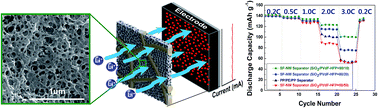
The never-ceasing pursuit of high-energy/high-power lithium-ion batteries, which have garnered a great deal of attention particularly in (hybrid) electric vehicle and grid-scale energy storage system applications, is having with serious issues related to the performance deterioration and safety failures of cells. Herein, to overcome these challenges, we demonstrate a new class of three-dimensionally interconnected, nanoporous poly(vinylidene fluoride–hexafluoropropylene) (PVdF–HFP) scaffold-embedded polyethylene terephthalate (PET) nonwoven composite separators (referred to as “SF-NW separators”) as a microporous membrane-based approach. Motivated by unique porous structure based on inverse replicas of densely-packed nanoparticle arrays, sacrificial colloidal silica (SiO2) template-mediated nanoarchitecturing is exploited to fabricate SF-NW separators. The selective removal of SiO2 nanoparticles dispersed in PVdF–HFP matrix allows for the formation of a nanoporous PVdF–HFP scaffold in a PET nonwoven, where the PET nonwoven acts as a compliant porous substrate providing mechanical/thermal stability. The nanoporous structure of SF-NW separators is fine-tuned by varying the SiO2/PVdF-HFP composition ratio. Owing to the highly-developed nanoporous PVdF–HFP scaffold, the SF-NW separator shows facile ionic transport and excellent electrolyte wettability; thus, contributing to the superior cell performance (particularly at high charge/discharge current densities) in comparison to conventional polyolefin separators.
Another critical challenge in high-energy/high-power density cells is safety failures.17–19 Notably, among various safety issues, internal short-circuit problems are known to be the most critical threat in securing cell safety, in which a separator is considered as a key component to suppress this failure, because its primary role is to maintain electrical isolation between the cathode and anode.14–16,20,21
Currently, the most widely used separators in commercial lithium-ion batteries are manufactured from polyolefins, predominantly polyethylene (PE) or polypropylene (PP). These polyolefin separators have many advantageous attributes suitable for practical use in lithium-ion batteries; however, their poor thermal stability, low porosity, and insufficient electrolyte wettability13–16,20 often results in serious concerns about the basic functions to ensure electrical isolation (related to cell safety) and ionic transport (cell performance) between electrodes.
Numerous attempts have been undertaken to overcome these shortcomings of conventional polyolefin separators. In particular, the use of porous nonwoven fabrics comprising multi-fibrous layers has attracted increasing attention because of their excellent thermal properties, high porosity, polarity, and cost competitiveness.22–30 However, the excessively large pore size and non-uniform pore size distribution of nonwoven fabrics may provoke the self-discharge and possibly internal short-circuit failure of the cells, which hinder their successful application as separators for lithium-ion batteries. To resolve these drawbacks of the nonwoven separators, several structure-tuning attempts have been reported, including the coating of inorganic powders/binders to nonwovens,22–24 fabrication of electrospun nanofiber nonwovens,25–27 and impregnation of gel polymer electrolytes into nonwovens.28–30
In the present study, we present a sacrificial colloidal silica (SiO2) template-mediated nanoarchitecturing strategy as a facile and scalable approach to fabricate advanced nonwoven separators with well-tailored porous structure and optimized attributes for use in high-performance/high-safety lithium-ion batteries. This new structural engineering concept is motivated by the inverse replicas of densely-packed nanoparticle arrays, which are used as an effective starting building block for the preparation of versatile-shaped micro- and nanoporous materials.31–36 To fabricate the nonwoven separators suggested herein, sacrificial SiO2 nanoparticles/polyvinylidene fluoride–hexafluoropropylene (PVdF–HFP) composites are combined with a polyethylene terephthalate (PET) nonwoven substrate. Subsequent removal of the sacrificial SiO2 nanoparticles dispersed in the PVdF–HFP matrix allows the formation of nanoporous PVdF–HFP scaffold (the nanopores correspond to the original locations of sacrificial SiO2 nanoparticles)-embedded PET nonwoven composite separator (hereinafter, referred to as “SF-NW separator”), in which the PET nonwoven acts as a compliant thermo-mechanical substrate that prevents the thermal shrinkage of the SF-NW separator. A salient benefit of the SF-NW separators is the provision of a simple and efficient strategy to fabricate separator membranes with a three dimensional (3D)-interconnected/highly-porous structure, which could allow for fast and facile ion transport via the separators. Moreover, the nanoporous structure of SF-NW separators can be fine-tuned by varying the SiO2/PVdF-HFP composition ratio.
Another important objective of this study is to quantitatively investigate the SiO2/PVdF-HFP composition ratio-dependent structural variation of the SF-NW separators. Membrane properties of the SF-NW separators, including porous structure (pore size, pore size distribution, and porosity), thermal shrinkage, electrolyte wettability, and ionic conductivity, are characterized as a function of SiO2/PVdF-HFP composition ratio and compared with those of a commercial tri-layer (polypropylene (PP)/polyethylene (PE)/polypropylene (PP)) separator, which is one of the most commonly used separators in large-sized cells aimed at (hybrid) electric vehicle and grid-scale energy storage system applications. On the basis of the comprehensive understanding of the membrane characteristics of SF-NW separators, their effects on the cell performance (in particular, under high-current density conditions) are scrutinized and discussed with an in-depth consideration of the structural uniqueness (i.e., nanoporous PVdF–HFP scaffolds) of SF-NW separators.
Φp (%) = {1 − [(WC/ρC + WN/ρN)/VS]} × 100 |
The subsequent removal of sacrificial SiO2 nanoparticles by HF (as an etching agent) leads to the construction of nanoporous PVdF–HFP scaffolds in the PET nonwovens (Fig. 2). The PVdF–HFP scaffolds that surround pores left in the original locations of sacrificial SiO2 nanoparticles are formed in the PET nonwovens, wherein average pore size appears to be 100 nm (corresponding to the initial SiO2 particle size). Furthermore, possibly due to an insufficient ordered-packing of SiO2 nanoparticles in the SiO2/PVdF-HFP precursors, perfectly uniform and well-defined pore structures have not yet been achieved in the SF-NW separators. Further work to enhance the morphological uniformity of the SF-NW separators will be undertaken in our future studies.
Consistent with the morphological results of the SiO2/PVdF-HFP precursors (Fig. 1), the nanoporous structure of the SF-NW separators is also dependent on the SiO2/PVdF-HFP composition ratio. At the SiO2/PVdF-HFP ratio of 50/50, sparsely scattered pores, which are poorly-interconnected because of the low concentration of sacrificial SiO2 nanoparticles, are formed inside the PVdF–HFP matrix (Fig. 2a). In comparison, the high SiO2/PVdF-HFP ratio (90/10) makes it possible to produce a well-developed nanoporous structure in the SF-NW separator (Fig. 2b). More specifically, 3D-networked, a large numbers of spherical nanopores besieged by the PVdF–HFP are generated, owing to the close-packed arrangement of sacrificial SiO2 nanoparticles in the SiO2/PVdF-HFP precursors.
The nanoporous structure of SF-NW separators was further analyzed by examining their cross-sectional morphology. Fig. 2c shows that the highly-reticulated PVdF–HFP scaffolds surrounding the nanopores are formed in the SF-NW separator (SiO2/PVdF-HFP = 90/10), verifying the successful evolution of 3D-interconnected porous channels in the thickness direction of the SF-NW separator. The nanopores of the SF-NW separators will be filled with liquid electrolytes during cell assembly, and thereupon act as ion-conducting routes. A comparison with the commercial PP/PE/PP separator, which has the less populated, slit-like pores formed between PP lamellar crystallines15 (here, the PP outer layer is observed in Fig. 2d), underscores the structural uniqueness of the SF-NW separators.
The nanoporous structure of SF-NW separators was quantitatively characterized by measuring their air permeability (i.e., Gurley values) and porosity. A low Gurley value of a separator represents high air permeability, i.e. short tortuous path for air transport.14–16 Table 1 shows that, as the SiO2 content is increased, the porous structure of SF-NW separators tends to be more developed (i.e., lower Gurley values and higher porosity). For example, the Gurley value and porosity of the SF-NW separator (fabricated from SiO2/PVdF-HFP = 50/50) are observed to be 300 s 100 cc−1 and 54.5%, respectively. On the other hand, the SF-NW separator (fabricated from SiO2/PVdF-HFP = 90/10) yields a lower Gurley value (35 s 100 cc−1) and higher porosity (60%), verifying the successful formation of a highly-interconnected porous structure in the SF-NW separator. This noticeable change in the Gurley values and porosity of SF-NW separators can be reasonably explained by considering their morphological results (Fig. 2).
Gurley value Sec 100 cc−1 air | Ionic conductivity mS cm−1 | Porosity% | McMullin number | Electrolyte uptake g cm−3 | |
---|---|---|---|---|---|
a Electrolyte: 1 M LiPF6 in EC/DEC = 1/1 v/v (σ = 7.552 mS cm−1 at 25 °C). | |||||
SF-NW separator (SiO2/PVdF-HFP = 50/50 w/w) | 300 | 0.55 | 54.5 | 13.7 | 0.96 |
SF-NW separator (SiO2/PVdF-HFP = 80/20 w/w) | 75 | 0.80 | 56.1 | 9.5 | 0.99 |
SF-NW separator (SiO2/PVdF-HFP = 90/10 w/w) | 35 | 0.93 | 60.0 | 8.2 | 1.06 |
PP/PE/PP separator | 500 | 0.60 | 40.0 | 12.5 | 0.73 |
The ionic conductivity of SF-NW separators was measured and discussed in terms of their nanoporous structure. Table 1 shows that the ionic conductivity of SF-NW separators increases from 0.55 to 0.93 mS cm−1 with an increase of sacrificial SiO2 content (50 → 90 wt%), which appears to be inversely proportional to the change in Gurley value. It has been reported in previous studies14–16,28–30 that air permeability, as represented by Gurley value, can be a useful parameter to possibly predict the ionic conductivity of separators; low Gurley value may indicate high ionic conductivity, although some inconsistencies are inevitably encountered. The high ionic conductivity (predicted from the low Gurley value and high porosity) of the SF-NW separator (SiO2/PVdF-HFP = 90/10) is a good evidence to show that the close-packed array of sacrificial SiO2 nanoparticles in the SiO2/PVdF-HFP precursor is an effective building block to enable the construction of the 3D-reticulated, highly porous PVdF–HFP scaffold in the SF-NW separator.
In addition, from these ionic conductivity results, the MacMullin number15,16 (NM = σo/σs, wherein σo = ionic conductivity of liquid electrolyte itself, σs = ionic conductivity of liquid electrolyte-filled separator) of SF-NW separators was estimated. The NM is known to reflect the loss of ionic conductivity because of the presence of an ionically-inert porous substrate (herein, a separator). Table 1 shows that the NM of SF-NW separators is decreased at higher SiO2 content (NM = 13.7 at SiO2/PVdF-HFP = 50/50 → 8.2 at SiO2/PVdF-HFP = 90/10), indicating that the SF-NW separator (SiO2/PVdF-HFP = 90/10) facilitates ionic transport owing to the highly-interconnected nanoporous PVdF–HFP scaffolds (filled with liquid electrolytes). This strong dependence of ionic conduction on the morphological variation of SF-NW separators is also conceptually illustrated (Fig. S2, ESI†). Moreover, the NM (8.2) of the SF-NW separator (SiO2/PVdF-HFP = 90/10) is found to be lower than that (12.5) of the PP/PE/PP separator. This result confirms the successful formation of highly-developed nanoporous structure, which facilitates ionic transport via the SF-NW separator (SiO2/PVdF-HFP = 90/10).
In order to explore the potential application of the SF-NW separator (here, SiO2/PVdF-HFP = 90/10 was chosen as a representative example) to cells with various sizes and shapes, its mechanical flexibility was investigated. Fig. 3a shows that the SF-NW separator can be folded at a bending angle of almost 180°. In addition, the dimensional stability of the SF-NW separator is preserved after being wound around a glass rod (diameter = 5 mm, Fig. 3b). Another notable finding is that the unique nanoporous PVdF–HFP scaffolds of the SF-NW separator are not impaired after being mechanically deformed (Fig. 3c). This result demonstrates that the SF-NW separator is highly flexible and structurally robust, and therefore can be readily applied to lithium-ion batteries with aesthetic diversity.
As lithium-ion batteries rapidly are extending to new application fields such as electric vehicles and energy storage systems that require large-sized cells, fast and uniform wetting of liquid electrolytes in cells is indispensably needed. Among major cell components, in particular, polyolefin separators are intrinsically hydrophobic, which thus often gives rise to electrolyte wetting problems.13–16,20 In comparison to the PP/PE/PP separator, the SF-NW separators are quickly wetted by the liquid electrolyte (1 M LiPF6 in EC/DEC = 1/1 v/v), in which the electrolyte droplets easily spread over a wide area of the SF-NW separators (Fig. S3a, ESI†). The electrolyte wettability of the SF-NW separators is also quantitatively evaluated by comparing the electrolyte immersion-height of the separators (Fig. 4a). After an elapsed time of 60 min, the SF-NW separators show higher electrolyte immersion-height than the PP/PE/PP separator. This improvement in the electrolyte wettability of the SF-NW separators can be explained by considering its relatively polar (i.e., electrolyte-philic) constituents and the well-interconnected nanoporous structure, both of which may facilitate capillary intrusion of the liquid electrolyte into the electrolyte-philic pores.24,29 Moreover, it should be noted that, as the content of the sacrificial SiO2 nanoparticles is increased, the electrolyte immersion-height of SF-NW separators becomes considerably higher (∼0.3 cm at SiO2/PVdF-HFP = 50/50 vs. ∼0.8 cm at SiO2/PVdF-HFP = 90/10). This result indicates that the more-developed nanoporous structure (generated from the larger SiO2 content) is advantageous in absorbing liquid electrolyte compared to the less-porous structure.
The thermal shrinkage of SF-NW separators (after exposure to 150 °C for 0.5 h), which is believed to strongly affect the internal short-circuit problems occurring between electrodes, was compared with that of the PP/PE/PP separator (Fig. 4b). The SF-NW separators, irrespective of the SiO2/PVdF-HFP composition ratio (Fig. S3b, ESI†), exhibit better thermal resistance (thermal shrinkage ∼ 0%) compared to the PP/PE/PP separator (thermal shrinkage ∼ 37%), indicating that the SF-NW separators could effectively prevent electrical contact, which triggers internal short-circuit failures, between electrodes. This remarkably suppressed thermal shrinkage of the SF-NW separators is attributed to the presence of thermally stable PET nonwoven substrates having a high melting temperature above 250 °C.24,28–30 In addition, the SF-NW separators were not subjected to stretching processes that are essentially used for manufacturing polyolefin separators,14–16 thereby contributing to the superior thermal stability.
The electrochemical stability window of the SF-NW separator (herein, SiO2/PVdF-HFP = 90/10 was chosen) was evaluated by analyzing linear sweep voltammograms (Fig. S4, ESI†). The overall voltammogram profile of the SF-NW separator appears to be comparable to that of the PP/PE/PP separator, although slightly lower oxidation potential is observed at the SF-NW separator. No significant decomposition of any components in the SF-NW separator takes place below 4.5 V vs. Li+/Li, revealing the good electrochemical stability of the SF-NW separator. In addition to the aforementioned electrochemical stability window, the cyclic voltammograms of the SF-NW separator were examined. Similar to the cell with the PP/PE/PP separator, the cell containing the SF-NW separator showed normal oxidation and reduction behavior (Fig. S5, ESI†).
An OCV drop, which is considered an important indicator to reflect the self-discharge of cells and possibly predict the risk of internal short-circuits occurring between electrodes, is known to be affected by the porous structure (specifically, pore size and pore size distribution) of separators.21–24,28–30 Fig. 5a shows that there is negligible difference in the OCV profiles between the SF-NW separator (SiO2/PVdF-HFP = 90/10) and the PP/PE/PP separator. By contrast, the cell assembled with the pristine PET nonwoven itself presents a sharp drop in OCV. This result verifies the strong dependence of OCV on the porous structure of the separators. In order to attain an in-depth understanding of this intriguing OCV behavior, the pore size and pore size distribution of separators were quantitatively estimated. Fig. 5b shows that the SF-NW separator has not only small pore size (average pore size ∼ 75 nm), but also narrow pore size distribution (most pores are below 0.2 μm in diameter) by the virtue of the presence of the nanoporous PVdF–HFP scaffold, which are comparable to those of the PP/PE/PP separator. On the other hand, the pristine PET nonwoven shows excessively large pore size (>5.0 μm) and broad pore size distribution, which may not be enough to prevent current leakage between the electrodes. This is well-consistent with the previous morphological characterization (Fig. 2). Hence, this OCV result demonstrates that the porous structure of the SF-NW separator is well tuned to prevent the self-discharge of cells.
The cell performance of SF-NW separators was examined at various charge/discharge conditions and correlated with their porous structure (i.e., PVdF–HFP scaffold). Fig. 6 depicts the discharge profiles of cells, wherein the cells were charged at a constant charge current density of 0.2 C under a voltage range of 3.0–4.2 V and discharged at current densities ranging from 0.2 to 3.0 C. As the SiO2/PVdF-HFP ratio is increased from 50/50 to 90/10, the SF-NW separators tend to show larger discharge capacities over a wide range of discharge current densities. This gap in the discharge capacities between the different SF-NW separators becomes more pronounced at higher discharge current densities in which the influence of ionic transport on the ohmic polarization is more significant.13–16 Fig. 6d summarizes the discharge capacities of the SF-NW separators as a function of discharge current density (i.e., discharge C-rate capability). The previous morphological results (Fig. 2) showed that, with increasing SiO2/PVdF-HFP ratio, a more porous structure is developed in the SF-NW separator, possibly yielding a shorter tortuous path for ionic movement. This structural advantage of the SF-NW separator plays a viable role in providing the higher ionic conductivity (Table 1), which in turn contributes to the substantial improvement of discharge C-rate capability.
Another intriguing finding is that the SF-NW separators fabricated from the larger SiO2 contents (i.e., SiO2/PVdF-HFP = 90/10 and 80/20) deliver better discharge C-rate capability compared to the commercial PP/PE/PP separator. It was previously observed in Table 1 that the SF-NW separators deliver the higher ionic conductivities (0.80 mS cm−1 at SiO2/PVdF-HFP = 80/20, 0.93 mS cm−1 at SiO2/PVdF-HFP = 90/10) compared to the PP/PE/PP separator (0.60 mS cm−1). As a result, this facile ionic transport due to the well-tuned nanoporous PVdF–HFP scaffolds enables the SF-NW separators to present a superior discharge performance (Fig. 6d).
As the scientific/industrial importance of lithium-ion batteries for (hybrid) electric vehicles is rapidly growing, enormous research activities are devoted to overcoming fast-charging issues of cells, in addition to the continuous pursuit of high discharge rate capability. Here, in order to explore the charge performance of a cell assembled with the SF-NW separator (SiO2/PVdF-HFP = 90/10), the cell was charged at various current densities ranging from 0.2 to 3.0 C (excluding CV (constant voltage) mode) under a constant discharge current density of 0.5 C. Fig. 7 exhibits, as charge current density is increased, the PP/PE/PP separator shows the unwanted rise of ohmic polarization. In comparison, the ohmic polarization during charging is suppressed in the SF-NW separator, leading to the larger charge capacities compared to the PP/PE/PP separator. This is important evidence to prove that ionic transport via a separator exerts considerable influence on cell polarization during the charging reaction.
In order to further elucidate the effect of separators on the fast-charging behavior of cells, the surface morphology of the charged graphite anodes (after the aforementioned test of charge rate capability) was analyzed. It is reasonably speculated that, when cells are charged at fast current densities, a significant portion of lithium ions may have difficulties in intercalating into graphite anodes; thus, possibly provoking the cell polarization and deposition of lithium dendrites on the anode surface.19,39–41 More importantly, it is known that undesirable growth of lithium dendrites during cycling often leads to internal short-circuit failures of cells, which are considered the most formidable threat in cell safety.4–8,15,28 Fig. 7c shows that, in the cell incorporating the PP/PE/PP separator, a substantial amount of needle and tubular-like lithium dendrites are deposited on the anode surface.42,43 By comparison, the relatively clean and smooth anode surface was observed at the cell with the SF-NW separator (Fig. 7d), underlining that the formation of lithium dendrites is remarkably prevented. In addition to the characterization of the anode surface, the separator surface was also examined after the fast charging test (Fig. S6, ESI†). Consistent with the results of the anode surface, the surface of the SF-NW separator was not contaminated with lithium dendrites, as compared to that of the PP/PE/PP separator. Along with the result on the discharge rate performance, the superior charge rate capability and the suppressed dendrite growth of SF-NW separator verify its potential applicability as a promising alternative to outperform a commercial PP/PE/PP separator for mid/large-sized cells (particularly, targeting (H)EV applications) that require high charge (associated with fast-charging)/discharge (power density) rate capability.
The cycling performance of the SF-NW separators was investigated as a function of SiO2/PVdF-HFP composition ratio, where the cells were cycled between 3.0 and 4.2 V at a fast charge/discharge current density (2.0 C/2.0 C). Fig. 8a shows that the charge/discharge capacity of the SF-NW separator (SiO2/PVdF-HFP = 50/50) sharply declines as the cycle number is increased, resulting in very low discharge capacity retention (∼40% after 100th cycle). In comparison to the SF-NW separator (SiO2/PVdF-HFP = 50/50) showing poor cyclability, the SF-NW separator fabricated from higher SiO2 content (SiO2/PVdF-HFP = 90/10) presents the better cycling performance. The capacity retention after the 100th cycle was found to be 98% (Fig. 8b). This result indicates that the cycling performance of the SF-NW separators is strongly influenced by their porous structures (more specifically, nanoporous PVdF–HFP scaffolds). Moreover, the long-term structural stability of the SF-NW separator (SiO2/PVdF-HFP = 90/10) after being subjected to repeated charge/discharge reactions was examined (Fig. S7, ESI†). Neither morphological disruption nor peel-off of nanoporous PVdF–HFP scaffolds is observed after the 100th cycle, indicating that the structural integrity of the SF-NW separator is well-preserved during the cycling test.
Another intriguing finding is that the SF-NW separator (SiO2/PVdF-HFP = 90/10) exhibits superior cycling performance compared to the PP/PE/PP separator (Fig. 8c, capacity retention after 100th cycle = 78%). It was already observed that the SF-NW separator (fabricated from the higher SiO2 content) has a highly-developed nanoporous PVdF–HFP scaffold (Fig. 2) and also a strong affinity for liquid electrolyte (Fig. 4a). As a consequence, the SF-NW separator with these advantageous characteristics, as compared to the PP/PE/PP separator with the low porosity, relatively nonuniform porous structure and poor electrolyte wettability, is expected to allow for facile ionic transport, good electrolyte retention and uniform electrolyte distribution between the separator and electrodes, thereby mitigating the polarization build-up at electrolyte–electrode interface during cycling.
Footnote |
† Electronic supplementary information (ESI) available. See DOI: 10.1039/c4ra07994a |
This journal is © The Royal Society of Chemistry 2014 |