DOI:
10.1039/C4RA08513B
(Paper)
RSC Adv., 2014,
4, 54335-54343
Tuning the magnetism of a ZrS2 monolayer by substitutional doping
Received
11th August 2014
, Accepted 16th October 2014
First published on 16th October 2014
Abstract
In view of the important role of developing efficient approaches to induce and manipulate the magnetism in semiconducting transition metal dichalcogenide monolayers for their application in low-dimensional spintronic devices, the influence of a series of transition metal (TM) (Sc, Ti, V, Cr, Mn, Fe, Co, Ni, Y, Nb and Mo), alkali metals (Li and Na) and alkaline-earth (Ca) dopants on the electronic structure and magnetic properties of a ZrS2 monolayer are investigated using first-principles calculations. It is shown that Ca, Sc, Ti, Ni and Y dopants cannot induce the magnetism in the doped ZrS2 monolayer and the stability of the magnetic state of the Na doped system is very small, while the ground state of Li, V, Cr, Mn, Fe, Co, Nb and Mo-doped systems are magnetic and the magnetic moment induced by 3d TM, 4d TM and Li dopants are mainly contributed by the 3d states of the 3d TM atom, the 4d states of the 4d TM atom and its nearing Mo atoms, and the 3p states of the S atoms and the interstitial region around Li, respectively. The evolutions of the magnetic moments with the different TM dopants, such as Ti, V, Cr, Mn, Fe, Co, Ni, Nb and Mo, can be interpreted in terms of a simple analysis based on the molecular orbitals and electron filling. Furthermore, the magnetic coupling between the moments induced by two Li, V, Cr, Fe, Co, Nb and Mo is long-range ferromagnetic and the coupling can be attributed to the hybridization interaction involving polarized electrons or holes, whereas the coupling between the moments induced by two Mn is anti-ferromagnetic. The calculated results suggest that substitutional doping of Li, V, Cr, Fe, Co and Mo atoms can induce the room temperature ferromagnetism in the ZrS2 monolayer.
1. Introduction
Since the fabrication of graphene, two dimensional (2D) materials have attracted a growing interest due to their intriguing physical and chemical properties with a wide range of promising applications.1–5 Recently, a significant amount of effort has been focused on investigating the magnetic properties of 2D materials for prospective applications in low-dimensional spintronic devices.5–16 It is well known that the operation of spintronic device requires generation and detection of tunable spin currents, which can ideally be done using a ferromagnetic semiconductor. Thus, the intrinsic zero band gap of graphene hinders its application in low-dimensional spintronics.17 Different from gapless graphene, a lot of the transition metal dichalcogenides (TMDs) single-layer sheets display a semiconducting feature with a moderate band gap16,18–21 and various kinds of TMDs few-layer nanosheets have been successfully synthesized by various methods,22–32 making them more suitable for applications in low-dimensional spintronics than graphene. Semiconducting TMDs monolayer being intrinsically diamagnetic in their pristine forms,16,19–21 developing approaches to effectively induce and manipulate the magnetism are required to facilitate use of magnetic TMDs monolayer in low-dimensional spintronic devices. As is known, substitutional doping is an efficient approach to tune the physical properties of the materials and has been widely used to induce and manipulate the magnetic states of the nonmagnetic semiconducting materials.33,34 In particular, a number of studies have confirmed that the substitution of transition metal (TM) atoms can induce magnetism in nonmagnetic nanomaterials.35–45 For example, the substitution of V, Cr, Mn, Co, Cu and Zn atoms in graphene are stable, and give rise to a remarkable magnetic moment.39 Likewise, Ren et al. reported that TM atoms can be effectively doped in ZnO monolayer and doping of Cr, Mn, Fe, Co, Ni, and Cu atoms can induce magnetization.40 Recently, some theoretical calculations shown that the MoS2 monolayer doped by some of TM atoms, such as V, Mn, Fe, Co, Ni, Zn, Cd and Hg, are magnetic.41–45 Correspondingly, Komsa et al. experimentally demonstrated that TMDs monolayer can be doped by filling the vacancies created by the electron beam with substitutional impurity atoms.46 In addition, this doping scheme has also been applied to other materials, including carbon nanotubes, graphene and boron nitride.47,48
As a member of the TMD family, ZrS2 monolayer is an indirect gap semiconductor with a bandgap of 1.1–1.2 eV (ref. 16, 21 and 49) and ZrS2-based field-effect-transistor devices with ultrafast response times and ultrahigh responsivity were fabricated.50 Moreover, high-yield monolayer ZrS2 nanosheets were synthesised in large amounts from its bulk material through a controllable lithiation process.28 These suggest that ZrS2 monolayer is also a promising host material to obtain 2D dilute magnetic semiconductor for low-dimensional spintronics applications. Recently, first-principles calculations shown that the strain can not induce the magnetism in pristine ZrS2 monolayer, though the tensile strain can induce the indirect-to-direct bandgap transition.16 It is therefore imperative to develop one effective approach to induce and manipulate the magnetism in ZrS2 monolayer. Compared with the wide research on functionalized MoS2 monolayer, the effects of substitutional dopants on the electronic structure and magnetic properties of ZrS2 monolayer have not been explored.
Here we systematically investigate the effects of a series of TM (Sc, Ti, V, Cr, Mn, Fe, Co, Ni, Y, Nb and Mo), alkali metals (Li and Na) and alkaline-earth (Ca) dopants on the electronic structure and magnetic properties of ZrS2 monolayer by using first-principle calculations and discuss the mechanism about the dopants induced magnetism in ZrS2 monolayer.
2. Computational details
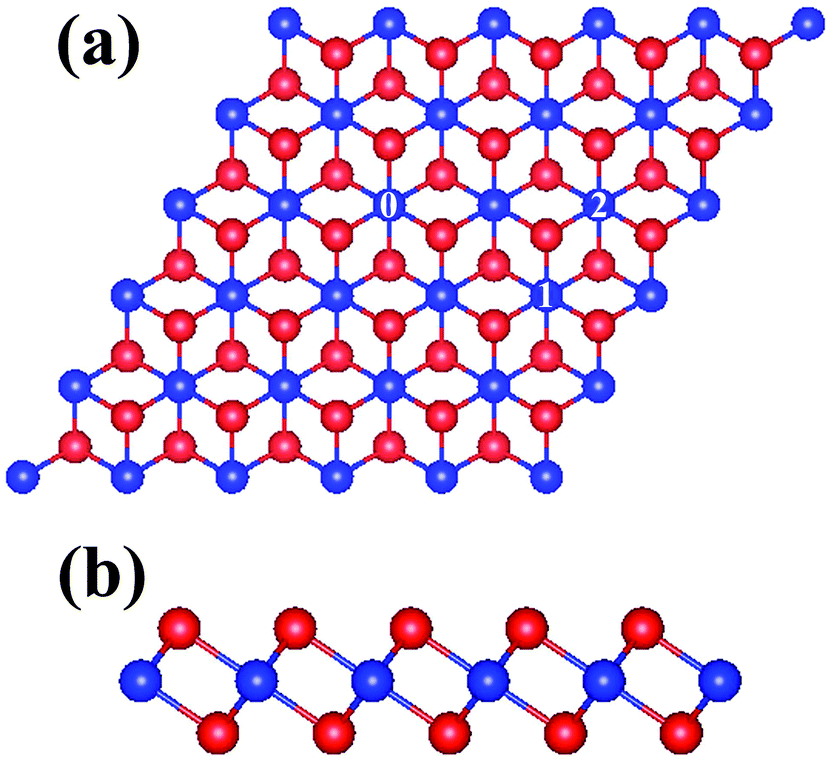
All calculations were performed within the framework of density functional theory (DFT), as implemented in Vienna ab-initio simulation package (VASP).51,52 The exchange–correlation potential was treated with the generalized gradient approximation with Perdew–Burke–Ernzerhof functional53 and the ion–electron interaction was described by the projector-augmented plane wave (PAW) potentials.54 The cutoff energy for the plane-wave basis was set to 500 eV and a 4 × 4 × 1 Monkhorst-Pack k-point mesh was used for the Brillouin zone integrations. The doped ZrS2 monolayer was modeled with a supercell consisting of 5 × 5 two-dimensional unit cells, which contains 75 atoms in total, as shown in Fig. 1. For Ti and Cr doped ZrS2 monolayer, a larger supercell consisting of 7 × 7 unit cells also used to check the convergence of our calculations. Since the ionicity of TM, alkaline-earth and alkali atom is closer to that of Zr, than S, it is expected that for atom substitution, the TM, alkaline-earth and alkali atom will occupy predominantly Zr site in doped monolayer ZrS2. Thus, doped systems were constructed with one or two dopant atoms to substitute host Zr atoms in the supercell. A vacuum space of 10 Å in the direction normal to the layers was used to avoid the interactions between adjacent monolayers. Both the atomic positions and cell parameters were optimized until the force on each atom was less than 0.01 eV Å−1. The optimized lattice parameters, S–Zr bond length, and S–Zr–S bond angle of pristine ZrS2 monolayer is calculated to be 3.70 Å, 2.58 Å and 88.45°, respectively, which are in good agreement with previous calculations.16,49
 |
| | Fig. 1 Top (a) and side (b) view of structure of the monolayer ZrS2 supercell. The blue and red balls represent Zr and S atoms, respectively. The positions of dopants are denoted by 0, 1 and 2, respectively. | |
3. Results and discussion
We first investigate the doped monolayer ZrS2 systems Zr24XS50 (X = Li, Na, Ca, Sc, Ti, V, Cr, Mn, Fe, Co, Ni, Y, Nb and Mo), in which a doping atom X occupies site 0 in the supercell, as shown in Fig. 1. To determine whether substitutional doping is energetically favorable, we calculate the formation energy Eform of substitutional dopant in doped ZrS2 monolayer and the calculated results under both Zr-rich and S-rich growth conditions are listed in Table 1. It can be seen from Table 1 that the S-rich condition is more energetically favorable for substitutional doping at the Zr site compared to the Zr-rich one. In consideration of the experimental report by Komsa et al.,46 where TMDs monolayer can be doped by filling the vacancies with substitutional impurity atoms, it appears that a promising scheme for atom doping at the Zr site in ZrS2 monolayer may be that of growing Zr poor samples and then of filling the vacancies with an appropriate Zr replacement. Table 1 also list the energy difference between the spin polarized and non-spin polarized state for Zr24XS50 (X = Li, Na, Ca, Sc, Ti, V, Cr, Mn, Fe, Co, Ni, Y, Nb and Mo), i.e., ΔESpin = Esp − Ensp. As listed in Table 1, ΔESpin of Ca, Sc, Ti, Ni and Y-doped ZrS2 monolayer are almost zero, suggesting that Ca, Sc, Ti, Ni and Y dopants cannot induce the magnetism in doped ZrS2 monolayer. In contrast, ground states of Li, Na, V, Cr, Mn, Fe, Co, Nb and Mo-doped system are magnetic because the spin-polarized state is more stable in energy than nonspin-polarized one. It is noticed that ΔESpin of Na-doped system is only −2.88 meV, indicating the very small stability of magnetic state. Thus spin-polarized state of Na-doped system is not stable at room temperature, since thermal excitation to nonspin-polarized state can easily occur.
Table 1 The energy difference (ΔESpin) between the spin polarized and non-spin polarized state and the formation energy (Eform) of substitutional dopant under Zr-rich and S-rich conditions for Zr24XS50 (X = Li, Na, Ca, Sc, Ti, V, Cr, Mn, Fe, Co, Ni, Y, Nb and Mo)
| System |
ΔESpin (meV) |
Eform (eV) |
| Zr-rich |
S-rich |
| Zr24LiS50 |
−19.71 |
5.94 |
1.32 |
| Zr24NaS50 |
−2.88 |
6.25 |
1.62 |
| Zr24CaS50 |
0.41 |
2.67 |
−1.96 |
| Zr24ScS50 |
−0.21 |
0.66 |
−3.97 |
| Zr24TiS50 |
0.00 |
1.07 |
−3.56 |
| Zr24VS50 |
−197.84 |
−1.41 |
−6.03 |
| Zr24CrS50 |
−815.32 |
4.00 |
−0.63 |
| Zr24MnS50 |
−1454.15 |
0.06 |
−4.57 |
| Zr24FeS50 |
−70.78 |
4.91 |
0.28 |
| Zr24CoS50 |
−13.35 |
5.38 |
0.75 |
| Zr24NiS50 |
0.00 |
5.22 |
0.59 |
| Zr24YS50 |
0.22 |
0.45 |
−4.18 |
| Zr24NbS50 |
−39.36 |
2.02 |
−2.60 |
| Zr24MoS50 |
−354.84 |
3.96 |
−0.67 |
The local magnetic moments of doping atom, Zr and S atoms and the magnetic moment of the supercell in the ground state are listed in Table 2. Owing to nonspin-polarized ground state, no magnetic moment was found for Ca, Sc, Ti, Ni and Y-doped ZrS2 monolayer. For the rest doping systems, which have magnetic ground states, we classify the substitutional dopants in to alkali metals, 3d TM and 4d TM with respect to the distribution of magnetic moments induced by dopant. It can be seen from Table 2 that most of the magnetic moments induced by 3d TM, 4d TM and alkali dopants come from the 3d TM atom, the 4d TM atom and its nearing Zr atoms, and S atoms and the interstitial part of the system, respectively. This magnetic moment distribution also can be drawn from the calculated spin density distribution in the relaxed Zr24XS50 (X = Li, Na, V, Cr, Mn, Fe, Co, Nb and Mo), as shown in Fig. 2. In addition, the calculations using the 7 × 7 supercell for Ti and Cr doped monolayer ZrS2 show that the formation energy of Ti and Cr dopant under Zr-rich and S-rich conditions converge within 0.04 eV, the energy difference between the spin polarized and non-spin polarized state for Cr doped system converge within 3.5 meV and the magnetic moments induced by Cr converge within 0.05 μB for calculations with the 5 × 5 supercell. These results show that the 5 × 5 supercell is enough to investigate doped monolayer ZrS2.
Table 2 The magnetic moment of the doping atom (Md), six nearest neighboring S atoms (MS1) and Zr atoms (MZr1) around dopant, other farther S atoms (MS2) and Zr atoms (MZr2) and the supercell (MSup) for Zr24XS50 (X = Li, Na, Ca, Sc, Ti, V, Cr, Mn, Fe, Co, Ni, Y, Nb and Mo)
| System |
Md (μB) |
MS1 (μB) |
MS2 (μB) |
MZr1 (μB) |
MZr2 (μB) |
MSup (μB) |
| Zr24LiS50 |
0.00 |
0.31 |
0.31 |
0.08 |
−0.01 |
1.64 |
| Zr24NaS50 |
0.00 |
0.16 |
0.19 |
−0.05 |
0.01 |
0.93 |
| Zr24CaS50 |
0.00 |
0.00 |
0.00 |
0.00 |
0.00 |
0.00 |
| Zr24ScS50 |
0.00 |
0.00 |
0.00 |
0.00 |
0.00 |
0.00 |
| Zr24TiS50 |
0.00 |
0.00 |
0.00 |
0.00 |
0.00 |
0.00 |
| Zr24VS50 |
1.04 |
−0.06 |
−0.01 |
0.07 |
0.01 |
0.98 |
| Zr24CrS50 |
2.36 |
−0.09 |
−0.09 |
0.08 |
0.02 |
2.11 |
| Zr24MnS50 |
3.01 |
−0.09 |
0.01 |
0.09 |
0.02 |
3.00 |
| Zr24FeS50 |
2.01 |
−0.05 |
0.02 |
0.04 |
0.01 |
2.00 |
| Zr24CoS50 |
0.46 |
0.01 |
0.10 |
0.00 |
0.00 |
0.90 |
| Zr24NiS50 |
0.00 |
0.00 |
0.00 |
0.00 |
0.00 |
0.00 |
| Zr24YS50 |
0.00 |
0.00 |
0.00 |
0.00 |
0.00 |
0.00 |
| Zr24NbS50 |
0.37 |
0.00 |
0.01 |
0.23 |
0.11 |
1.00 |
| Zr24MoS50 |
1.51 |
0.02 |
0.00 |
0.18 |
0.05 |
2.00 |
 |
| | Fig. 2 Spin density distribution of the relaxed Zr24XS50 (X = Li, Na, V, Cr, Mn, Fe, Co, Nb and Mo). The yellow and light blue isosurfaces correspond to the majority- and minority-spin densities. The blue, red and pink balls represent Zr, S and doping X atoms, respectively. | |
In the following, we discuss the origin of the magnetism for alkali metals, 3d and 4d TM doping as well as the absence of magnetism in the case of Ca, Sc, Ti, Ni and Y substitutions. Fig. 3 shows the total density of states (DOS) of Zr24XS50 (X = Li, Na, Ca, Sc, and Y) and the partial DOS of dopant X and its nearest S atom. For comparison, the total and partial DOS of pristine ZrS2 monolayer are also presented in Fig. 3. As can be seen in Fig. 3, the substitutional doping by monovalent alkali metals (Li and Na), divalent alkaline-earth (Ca) and trivalent TM (Sc and Y) atoms creates impurity states just above the top of the valence band, thus introducing some holes at the top of the valence band. Moreover, as the valence electrons of the dopant increase in number, the introduced holes decrease gradually, as shown in Fig. 3. Also from the DOS in Fig. 3 one can see that the introduced holes are mainly confined to the 3p orbitals of the S atoms around dopant. Fig. 4 shows the band structure of pristine ZrS2 and Zr24XS50 (X = Li, Na, Ca, Sc, and Y). As shown in Fig. 4, for Li and Na-doped ZrS2 monolayer, the impurity bands crossed by the Fermi level have relative small bandwidth, which is lower than a limit value that determines the zero energy instability, so that the mean kinetic energy of these bands is close to zero. According to the usual zero energy instability effect,55 the zero kinetic energy of the band crossed by the Fermi level allows the spin splitting of this one due to the exchange interaction, thus resulting in magnetic ground state of Li and Na-doped ZrS2 monolayer. Moreover, the bandwidth of the bands crossed by the Fermi level for Na doped system being larger than that for Li doped ZrS2, the stability of magnetic state of Na-doped system is weak compared with Li doped ZrS2. In contrast, in the case of Ca, Sc and Y as the dopant, the bands crossed by the Fermi level show a large dispersion along the high-symmetry lines as shown in Fig. 4, indicating extended character of the bands crossed by the Fermi level. As well known, the extended states usually favor non-spin polarization due to the higher kinetic energy. This is the reason why Ca, Sc and Y substitution cannot induce the magnetism in doped ZrS2 monolayer.
 |
| | Fig. 3 Total DOS of pristine ZrS2 monolayer and doped system Zr24XS50 (X = Li, Na, Ca, Sc, and Y) and corresponding partial DOS of d or s orbitals of dopant X (Zr) atom and p orbitals of a nearest S atom around X (Zr). The Fermi level is indicated by the vertical dashed line. | |
 |
| | Fig. 4 Band structure of pristine ZrS2 monolayer and doped system Zr24XS50 (X = Li, Na, Ca, Sc, and Y). The Fermi level is indicated by the horizontal dashed line. | |
In the case of 3d and 4d TM atom as the dopant, as the number of electrons in the d orbital of TM atom increase, the magnetic moment induced by TM atom increases from V (Nb) to Cr (Mo), and a maximum appears in Mn, and then decreases gradually until it vanishes at Ni. To understand above evolutions of the magnetic moments with the different TM dopant considered, let us consider a simple model analysis, based on the molecular orbitals and electron filling. Fig. 5(a) and (b) show the schematic molecular orbitals diagrams of TM doped ZrS2 monolayer for strong and weak exchange splitting, respectively. The structure of ZrS2 monolayer is hexagonal lattice with space group P![[3 with combining macron]](https://www.rsc.org/images/entities/char_0033_0304.gif) m1 (D3d point group), in which the Zr atoms are centered at a trigonal anti-prism constructed of six S atoms, as shown in Fig. 1. As well known, in a trigonal anti-prismatic environment, the five-fold degenerate TM d levels split into two twofold degenerate levels 1eg (dxy and dyz) and 2eg (dxy and dx2−y2) and a non-degenerate level a (dz2), where ordering of the levels after crystal splitting is a < 2eg < 1eg, with increasing energy, as shown on the left hand side of Fig. 5. Exchange interaction further split these levels into majority and minority spin levels, as shown in Fig. 5. The dangling bonds surrounding the TM dopant form two twofold degenerate levels 1eg (p) and 2eg (p) and two non-degenerate levels 1a and 2a, as shown on the right hand side of Fig. 5. The levels formed by the dangling bonds are weakly spin polarized on account of the rather delocalized nature of these dangling bond orbitals. The fully occupied 1a and 2a levels occur as a resonance in the host valence band, whereas the 1eg (p) and 2eg (p) levels of the dangling bond couple with the crystal field split 1eg and 2eg levels of the TM dopant, respectively, forming twofold degenerate bonding and anti-bonding 1eg and 2eg type levels, as shown in the central panel of Fig. 5. In contrast, the non-degenerate a level of the TM dopant remains largely unperturbed since the host does not have localized a state in this energy range. As shown in Fig. 5, the twofold degenerate bonding levels are buried deep into the valence bands and are weakly spin polarized because they are composed mainly of the dangling bond states. The nonbonding a level and the anti-bonding 1eg and 2eg levels decrease in energy as the number of electrons in the d orbital of TM atom increase. Now we fill the molecular orbitals as sketched in Fig. 5, where the filling electrons that should be considered are the d and s electrons of TM and the p electrons of S,56 that are from 12 up to 18 electrons for Zr24TiS50 to Zr24NiS50. For Ti doped system, 12 electrons fully occupy the nonbonding 1a and 2a levels and the bonding 1eg and 2eg levels, which result in an equal number of majority- and minority-spin occupied states, thus driving the system into a nonmagnetic state, as confirmed by the DOS of Zr24TiS50 in Fig. 6. In the case of V(Nb), Cr(Mo) and Mn doped ZrS2, the antibonding 1eg and 2eg majority-spin levels are lower in energy than the nonbonding a minority-spin level due to a strong exchange splitting, as shown in Fig. 5(a). Hence the electrons now fill the majority-spin channel of the nonbonding a level and the anti-bonding levels first before filling the minority-spin channel. Thus the highest occupied level is the nonbonding a majority-spin level for V(Nb) doped system while it is mainly the antibonding 2eg majority-spin levels for Cr(Mo) and Mn doped systems, the nonbonding a minority-spin level being empty. As a result, it is expected the magnetic moment induced by V(Nb), Cr(Mo) and Mn to be 1.0, 2.0 and 3.0 μB per dopant, respectively. In contrast, for Fe, Co, and Ni doped ZrS2, the exchange splitting is relatively weak. Consequently, the nonbonding a level and the antibonding 1eg and 2eg levels do not cross, as shown in Fig. 5(b), so that the electrons sequentially fill both the majority-spin and minority-spin channel for each level. Thus the magnetic moment induced by Fe and Co is 2.0 and 1.0 μB, respectively, and decrease to 0 for Ni doped ZrS2 since both majority-spin and minority-spin channels of the antibonding 2eg levels are fully occupied, i.e. the occupation of majority-spin and minority-spin channels are equal. The actual magnetic moment induced by Co is somewhat lower because of the majority-spin 2eg level is not fully occupied, as shown in Fig. 6. This simple model picture is confirmed by the total and partial DOS of Zr24XS50 (X = Ti, V, Cr, Mn, Fe, Co, Ni, Nb and Mo) shown in Fig. 6.
m1 (D3d point group), in which the Zr atoms are centered at a trigonal anti-prism constructed of six S atoms, as shown in Fig. 1. As well known, in a trigonal anti-prismatic environment, the five-fold degenerate TM d levels split into two twofold degenerate levels 1eg (dxy and dyz) and 2eg (dxy and dx2−y2) and a non-degenerate level a (dz2), where ordering of the levels after crystal splitting is a < 2eg < 1eg, with increasing energy, as shown on the left hand side of Fig. 5. Exchange interaction further split these levels into majority and minority spin levels, as shown in Fig. 5. The dangling bonds surrounding the TM dopant form two twofold degenerate levels 1eg (p) and 2eg (p) and two non-degenerate levels 1a and 2a, as shown on the right hand side of Fig. 5. The levels formed by the dangling bonds are weakly spin polarized on account of the rather delocalized nature of these dangling bond orbitals. The fully occupied 1a and 2a levels occur as a resonance in the host valence band, whereas the 1eg (p) and 2eg (p) levels of the dangling bond couple with the crystal field split 1eg and 2eg levels of the TM dopant, respectively, forming twofold degenerate bonding and anti-bonding 1eg and 2eg type levels, as shown in the central panel of Fig. 5. In contrast, the non-degenerate a level of the TM dopant remains largely unperturbed since the host does not have localized a state in this energy range. As shown in Fig. 5, the twofold degenerate bonding levels are buried deep into the valence bands and are weakly spin polarized because they are composed mainly of the dangling bond states. The nonbonding a level and the anti-bonding 1eg and 2eg levels decrease in energy as the number of electrons in the d orbital of TM atom increase. Now we fill the molecular orbitals as sketched in Fig. 5, where the filling electrons that should be considered are the d and s electrons of TM and the p electrons of S,56 that are from 12 up to 18 electrons for Zr24TiS50 to Zr24NiS50. For Ti doped system, 12 electrons fully occupy the nonbonding 1a and 2a levels and the bonding 1eg and 2eg levels, which result in an equal number of majority- and minority-spin occupied states, thus driving the system into a nonmagnetic state, as confirmed by the DOS of Zr24TiS50 in Fig. 6. In the case of V(Nb), Cr(Mo) and Mn doped ZrS2, the antibonding 1eg and 2eg majority-spin levels are lower in energy than the nonbonding a minority-spin level due to a strong exchange splitting, as shown in Fig. 5(a). Hence the electrons now fill the majority-spin channel of the nonbonding a level and the anti-bonding levels first before filling the minority-spin channel. Thus the highest occupied level is the nonbonding a majority-spin level for V(Nb) doped system while it is mainly the antibonding 2eg majority-spin levels for Cr(Mo) and Mn doped systems, the nonbonding a minority-spin level being empty. As a result, it is expected the magnetic moment induced by V(Nb), Cr(Mo) and Mn to be 1.0, 2.0 and 3.0 μB per dopant, respectively. In contrast, for Fe, Co, and Ni doped ZrS2, the exchange splitting is relatively weak. Consequently, the nonbonding a level and the antibonding 1eg and 2eg levels do not cross, as shown in Fig. 5(b), so that the electrons sequentially fill both the majority-spin and minority-spin channel for each level. Thus the magnetic moment induced by Fe and Co is 2.0 and 1.0 μB, respectively, and decrease to 0 for Ni doped ZrS2 since both majority-spin and minority-spin channels of the antibonding 2eg levels are fully occupied, i.e. the occupation of majority-spin and minority-spin channels are equal. The actual magnetic moment induced by Co is somewhat lower because of the majority-spin 2eg level is not fully occupied, as shown in Fig. 6. This simple model picture is confirmed by the total and partial DOS of Zr24XS50 (X = Ti, V, Cr, Mn, Fe, Co, Ni, Nb and Mo) shown in Fig. 6.
 |
| | Fig. 5 Schematic energy level diagram of TM doped ZrS2 monolayer for strong (a) and weak exchange splitting (b), where Mn and Co doping correspond to strong and weak exchange splitting, respectively. | |
 |
| | Fig. 6 Total DOS of doped system Zr24XS50 (X = Ti, V, Cr, Mn, Fe, Co, Ni, Nb and Mo) and corresponding partial DOS of d orbitals of dopant X atom and p orbitals of a nearest S atom around X. The Fermi level is indicated by the vertical dashed line. | |
To further study the magnetic coupling between the moments induced by dopants, we investigated the doped monolayer ZrS2 systems Zr23X2S50 (X = Li, V, Cr, Mn, Fe, Co, Nb and Mo), in which two Zr atoms are substituted by dopant X in a supercell. In the light of very small stability of magnetic state, the magnetic coupling between the moments in Na-doped system has not been investigated. Here we consider two positional configurations for two dopants in the supercell, where the first dopant X occupies site 0 and second occupies the 1 and 2 sites, respectively, as shown in Fig. 1, and the two configurations are labeled as (0,1) and (0,2), respectively. For each configuration, the spin-polarized calculations were performed, considering antiferromagnetic (AFM) and ferromagnetic (FM) coupling between the moments induced by two dopants, respectively. The energy difference between FM and AFM states for each configuration of Zr23X2S50 (X = Li, V, Cr, Mn, Fe, Co, Nb and Mo), i.e. ΔEm = EFM − EAFM, is listed in Table 3. For the magnetic ground state of each configuration, the relaxed distance between the two dopants, and the magnetic moment of the supercell are also listed in Table 3. It can be seen from Table 3 that for Li, V, Cr, Fe, Co, Nb and Mo doped systems, ground states of the configurations (0,1) and (0,2) all are FM, except for Mn doped system, whose ground state is found to be AFM. More importantly, Table 3 shows that for Li, V, Cr, Fe, Co and Mo doped systems, ΔEm of the configuration (0,2) with large distance between the dopants is a large negative value, which suggest that room temperature ferromagnetism is likely achieved in ZrS2 monolayer by doping Li, V, Cr, Fe, Co and Mo. Moreover the magnetic moments induced by each dopant X in the FM or AFM state are almost the same as that for Zr24XS50.
Table 3 The relaxation distance (d), the energy difference (ΔEm), and the magnetic moment of the supercell (MSup) in FM/AFM ground state
| System |
Configuration (0,i) |
d (Å) |
ΔEm (meV) |
MSup (μB) |
| Zr24LiS50 |
(0,1) |
6.75 |
−23.02 |
3.05 |
| (0,2) |
7.59 |
−80.93 |
3.10 |
| Zr24VS50 |
(0,1) |
6.25 |
−33.16 |
2.02 |
| (0,2) |
7.14 |
−47.74 |
1.97 |
| Zr24CrS50 |
(0,1) |
6.28 |
−66.26 |
4.07 |
| (0,2) |
7.23 |
−61.55 |
4.11 |
| Zr24MnS50 |
(0,1) |
6.26 |
2.61 |
0.00 |
| (0,2) |
6.99 |
21.54 |
0.00 |
| Zr24FeS50 |
(0,1) |
6.27 |
−62.40 |
4.00 |
| (0,2) |
7.10 |
−117.17 |
4.01 |
| Zr24CoS50 |
(0,1) |
6.28 |
−40.12 |
2.01 |
| (0,2) |
7.23 |
−65.73 |
1.97 |
| Zr24NbS50 |
(0,1) |
6.34 |
−6.49 |
2.00 |
| (0,2) |
7.22 |
−27.18 |
2.00 |
| Zr24MoS50 |
(0,1) |
6.32 |
−72.13 |
4.00 |
| (0,2) |
7.22 |
−82.15 |
4.00 |
The mechanism of long-range magnetic coupling between the magnetic moments induced by dopants can be explained based on the analysis of the calculated DOS and spin density distribution. The DOS of Zr23X2S50 (X = V, Cr, Mn, Fe, Co, Nb and Mo) in Fig. 7 reveal that the d states of the TM dopant, the 3p states of the S atoms around TM and the 4d states of the Zr atoms around TM overlap near the Fermi level, which suggest that the TM dopant hybridizes with its neighboring S and Zr atoms.57 Similarly, the DOS of Zr23Li2S50 in Fig. 7 also suggest that there is a strong p–p hybridization interaction between the 3p states of the S atoms around Li. It has been reported that the introduced electrons in the 3p orbitals of the S atoms around TM and the 4d orbitals of the Zr atoms around TM can couple with the d orbitals of the TM dopant through this hybridization interaction, and the introduced holes in 3p orbitals of the S atoms around Li can also couple with each other through the p–p interaction.57–59 Indeed, the calculated spin density in Fig. 8 shows that the S and Zr atoms around each dopant X are polarized to different degrees depending on their orientation and distances relative to X site. Also it can be seen from Fig. 8 that the spins orientations of the S and Zr atoms around TM dopant are parallel or anti-parallel to that of TM dopant, and the spins orientations of the S atoms around Li are parallel to each other under the hybridization interaction. As a result, the electrons (holes) localized around the S and Zr atoms between two dopants X in the supercell are polarized as shown in Fig. 8. It can be seen from DOS of Zr23X2S50 (X = Li, V, Cr, Fe, Co, Nb and Mo) in Fig. 7 that all states at the Fermi level are almost states of one spin channel and they are partially occupied, while another spin states are insulating. Consequently, when the spin of the TM atoms (or the spin of S atoms around Li) are parallel to each other, the spin-conserving hopping for electrons (or holes) from the d orbitals of one TM atom (or the 3p orbitals of one S atom around Li) to the d orbitals of other neighboring TM atom (or the 3p orbitals of other neighboring S atom) is allowed due to the strong intra-atomic exchange interaction between the electrons in d (3p) level, thus lowering the kinetic and exchange energies relative to the antiparallel spin alignment. Therefore, the polarized mobile electrons (holes) between two dopants X are able to effectively mediate an indirect long-range FM coupling between the magnetic moments induced by dopants X as reported by ref. 57 and 59. In contrast, DOS of Zr23Mn2S50 in Fig. 7 show that the minority-spin 3d states of Mn atom near the Fermi level are fully occupied whereas the higher energy majority-spin 3d states of Mn atom are empty. As mentioned above, the spin-conserving hopping for electrons from the occupied 3d orbitals of one Mn atom to the same-spin unoccupied 3d orbitals of other neighboring Mn atom lowers energy of system when the spin alignment of the two Mn is antiparallel while such hopping is not allowed when the spin alignment is parallel, thus resulting in a AFM coupling between the magnetic moments induced by two Mn.
 |
| | Fig. 7 Total DOS of FM/AFM ground state for the configuration (0,1) of Zr23X2S50 (X = Li, V, Cr, Fe, Co, Nb, Mo and Mn) and corresponding partial DOS of d or s orbitals of a dopant X atom, p orbitals of a nearest S atom around X and d orbitals of a Zr atom around X. The Fermi level is indicated by the vertical dashed line. | |
 |
| | Fig. 8 The spin density distribution of FM/AFM ground state for the configuration (0,1) of relaxed Zr23X2S50 (X = Li, V, Cr, Fe, Co, Nb, Mo and Mn). The yellow and light blue isosurfaces correspond to the majority- and minority-spin densities. The blue, red and pink balls represent Zr, S and doping X atoms, respectively. | |
4. Conclusions
In summary, ground state of alkali (Li and Na) doped ZrS2 monolayer are magnetic due to the zero kinetic energy of the band crossed by the Fermi level and the stability of magnetic state of Na-doped system is very weak, whereas Ca, Sc and Y dopants can not induce the magnetism in doped system due to extended character of the bands crossed by the Fermi level. In the case of other 3d and 4d TM atom as the dopant, Ti and Ni dopants cannot induce the magnetism in doped ZrS2 monolayer while ground state of V, Cr, Mn, Fe, Co, Nb and Mo-doped system are magnetic, and the evolutions of the magnetic moments with these TM dopant considered is interpreted based on the molecular orbitals and electron filling. More interestingly, the magnetic coupling between magnetic moments induced by two Li, V, Cr, Fe, Co, Nb and Mo is found to be long-range FM, and the calculated DOS and the spin density distribution show that the hybridization interaction involving polarized electrons (holes) is responsible for the FM coupling. In contrast, an AFM coupling occurs between the moments induced by two Mn. Our results show substitutional doping at the Zr site can provide an effective approach to tune the magnetism in monolayer ZrS2 based low-dimensional spintronic devices.
Acknowledgements
This work was supported by the National Natural Science Foundation of China (11174104), International Collaborative Research Program of China (2011DFR01060) and the National Fund for Fostering Talents of Basic Science (J1103202). The authors acknowledge the computational support provided by High Performance Computing Center of Jilin University, China.
References
- A. K. Geim and K. S. Novoselov, Nat. Mater., 2007, 6, 183 CrossRef CAS PubMed.
- C. H. Jin, F. Lin, K. Suenaga and S. Iijima, Phys. Rev. Lett., 2009, 102, 195505 CrossRef.
- L. Z. Kou, T. Frauenheim and C. F. Chen, J. Phys. Chem. Lett., 2013, 4, 1730–1736 CrossRef CAS.
- K. L. He, C. Poole, K. F. Mak and J. Shan, Nano Lett., 2013, 13, 2931–2936 CrossRef CAS PubMed.
- Y. W. Son, M. L. Cohen and S. G. Louie, Phys. Rev. Lett., 2006, 97, 216803 CrossRef.
- B. Huang, H. J. Xiang, J. Yu and S. H. Wei, Phys. Rev. Lett., 2012, 108, 206802 CrossRef.
- O. V. Yazev, Rep. Prog. Phys., 2010, 73, 056501 CrossRef.
- S. Mathew, K. Gopinadhan, T. K. Chan, X. J. Yu, D. Zhan, L. Cao, A. Rusydi, M. B. H. Breese, S. Dhar, Z. X. Shen, T. Venkatesan and J. T. L. Thong, Appl. Phys. Lett., 2012, 101, 102103 CrossRef PubMed.
- B. Ouyang and J. Song, Appl. Phys. Lett., 2013, 103, 102401 CrossRef PubMed.
- Y. D. Ma, Y. Dai, M. Guo, C. W. Niu, Y. T. Zhu and B. B. Huang, ACS Nano, 2012, 6, 1695–1701 CrossRef CAS PubMed.
- Y. G. Zhou, Z. G. Wang, P. Yang, X. T. Zu, L. Yang, X. Sun and F. Gao, ACS Nano, 2012, 6, 9727–9736 CrossRef CAS PubMed.
- H. L. Shi, H. Pan, Y. W. Zhang and B. I. Yakobson, Phys. Rev. B: Condens. Matter Mater. Phys., 2013, 88, 205305 CrossRef.
- H. Pan and Y. W. Zhang, J. Phys. Chem. C, 2012, 116, 11752–11757 CAS.
- Y. G. Zhou, Q. L. Su, Z. G. Wang, H. Q. Deng and X. T. Zu, Phys. Chem. Chem. Phys., 2013, 15, 18464–18470 RSC.
- H. L. Zheng, B. S. Yang, D. D. Wang, R. L. Han, X. B. Du and Y. Yan, Appl. Phys. Lett., 2014, 104, 132403 CrossRef PubMed.
- H. Y. Guo, Y. Zhao, N. Lu, E. Kan, X. C. Zeng, X. J. Wu and J. L. Yang, J. Phys. Chem. C, 2012, 116, 11336–11342 CAS.
- L. Y. Jiao, L. Zhang, X. R. Wang, G. Diankov and H. J. Dai, Nature, 2009, 458, 877 CrossRef CAS PubMed; M. Y. Han, B. Özyilmaz, Y. B. Zhang and P. Kim, Phys. Rev. Lett., 2007, 98, 206805 CrossRef; X. L. Li, X. R. Wang, L. Zhang, S. Lee and H. J. Dai, Science, 2008, 319, 1229 CrossRef PubMed; F. Schwierz, Nat. Nanotechnol., 2010, 5, 487 CrossRef PubMed.
- K. F. Mak, C. Lee, J. Hone, j. Shan and T. F. Heinz, Phys. Rev. Lett., 2010, 105, 036805 CrossRef.
- H. L. Shi, H. Pan, Y. W. Zhang and B. I. Yakobson, Phys. Rev. B: Condens. Matter Mater. Phys., 2013, 87, 155304 CrossRef.
- C. Ataca, H. Sahin and S. Ciraci, J. Phys. Chem. C, 2012, 116, 8983–8999 CAS.
- S. Lebègue, T. Björkman, M. Klintenberg, R. M. Nieminen and O. Eriksson, Phys. Rev. X, 2013, 3, 031002 Search PubMed.
- J. N. Coleman, M. Lotya, A. O'Neill, S. D. Bergin, P. J. King, U. Khan, K. Young, A. Gaucher, S. De, R. J. Smith, I. V. Shvets, S. K. Arora, G. Stanton, H. Y. Kim, K. Lee, G. T. Kim, G. S. Duesberg, T. Hallam, J. J. Boland, J. J. Wang, J. F. Donegan, J. C. Grunlan, G. Moriarty, A. Shmeliov, R. J. Nicholls, J. M. Perkins, E. M. Grieveson, K. Theuwissen, D. W. McComb, P. D. Nellist and V. Nicolosi, Science, 2011, 331, 568 CrossRef CAS PubMed.
- A. Splendiani, L. Sun, Y. Zhang, T. S. Li, J. W. Kim, C. Y. Chim, G. Galli and F. Wang, Nano Lett., 2010, 10, 1271–1275 CrossRef CAS PubMed.
- Y. J. Zhan, Z. Liu, S. Najmaei, P. M. Ajayan and J. Lou, Small, 2013, 8, 966–971 CrossRef PubMed.
- W. Zhou, X. L. Zou, S. Najmaei, Z. Liu, Y. M. Shi, J. Kong, J. Lou, P. M. Ajayan, B. I. Yakobson and J. C. Idrobo, Nano Lett., 2013, 13, 2615–2622 CrossRef CAS PubMed.
- S. Tongay, S. S. Varnoosfaderani, B. R. Appleton, J. Wu and A. F. Hebard, Appl. Phys. Lett., 2013, 101, 123105 CrossRef PubMed.
- S. Tongay, J. Zhou, C. Ataca, K. Lo, T. S. Matthews, J. B. Li, J. C. Grossman and J. Q. Wu, Nano Lett., 2013, 12, 5576–5580 CrossRef PubMed.
- Z. Y. Zeng, Z. Y. Yin, X. Huang, H. Li, Q. Y. He, G. Lu, F. Boey and H. Zhang, Angew. Chem., Int. Ed., 2011, 50, 11093–11097 CrossRef CAS PubMed.
- S. Jeong, D. Yoo, J. T. Jang, M. Kim and J. Cheon, J. Am. Chem. Soc., 2012, 134, 18233–18236 CrossRef CAS PubMed.
- C. Lee, Q. Y. Li, W. Kalb, X. Z. Liu, H. Berger, R. W. Carpick and J. Hone, Science, 2010, 328, 76 CrossRef CAS PubMed.
- H. S. Matte, A. Gomathi, A. K. Manna, D. J. Late, R. Datta, S. K. Pati and C. N. Rao, Angew. Chem., Int. Ed., 2010, 49, 4059–4062 CrossRef CAS PubMed.
- H. Li, G. Lu, Y. L. Wang, Z. Y. Yin, C. X. Cong, Q. Y. He, L. Wang, F. Ding, T. Yu and H. Zhang, Small, 2013, 9, 1974–1981 CrossRef CAS PubMed.
- T. Dietl, Nat. Mater., 2013, 9, 965 CrossRef PubMed.
- K. Sato, L. Bergqvist, J. Kudrnovský, P. H. Dederichs, O. Eriksson, I. Turek, B. Sanyal and G. Bouzerar, et al., Rev. Mod. Phys., 2010, 82, 1633 CrossRef CAS.
- E. Durgun, D. I. Bilc, S. Ciraci and P. Ghosez, J. Phys. Chem. C, 2012, 116, 15713–15772 CAS.
- C. Ataca and S. Ciraci, J. Phys. Chem. C, 2011, 115, 13303–13311 CAS.
- C. Ataca and S. Ciraci, Phys. Rev. B: Condens. Matter Mater. Phys., 2010, 82, 165402 CrossRef.
- Y. Xie and J. M. Zhang, Comput. Theor. Chem., 2011, 976, 215–220 CrossRef CAS PubMed.
- A. V. Krasheninnikov, P. O. Lehtinen, A. S. Foster, P. Pyykkö and R. M. Nieminen, Phys. Rev. Lett., 2009, 102, 126807 CrossRef CAS.
- J. Ren, H. Zhang and X. L. Cheng, Int. J. Quantum Chem., 2013, 113, 2243–2250 CrossRef CAS.
- K. Dolui, I. Rungger, C. D. Pemmaraju and S. Sanvito, Phys. Rev. B: Condens. Matter Mater. Phys., 2013, 88, 075420 CrossRef.
- Y. C. Cheng, Z. Y. Zhu, W. B. Mi, Z. B. Guo and U. Schwingenschögl, Phys. Rev. B: Condens. Matter Mater. Phys., 2013, 87, 100401(R) CrossRef.
- A. Ramasubramaniam and D. Naveh, Phys. Rev. B: Condens. Matter Mater. Phys., 2013, 87, 195201 CrossRef.
- R. Mishra, W. Zhou, S. J. Pennycook, S. T. Pantelides and J. C. Idrobo, Phys. Rev. B: Condens. Matter Mater. Phys., 2013, 88, 144409 CrossRef.
- W. S. Yun and J. D. Lee, Phys. Chem. Chem. Phys., 2014, 16, 8990–8996 RSC.
- H. P. Komsa, J. Kotakoski, S. Kurasch, O. Lehtinen, U. Kaiser and A. V. Krasheninnikov, Phys. Rev. Lett., 2012, 109, 035503 CrossRef.
- J. A. Rodríguez-Manzo, O. Cretu and F. Banhart, ACS Nano, 2010, 4, 3422–3428 CrossRef PubMed.
- X. L. Wei, M. S. Wang, Y. Bando and D. Golberg, ACS Nano, 2011, 5, 2916–2922 CrossRef CAS PubMed.
- H. L. Zhuang and R. G. Hennig, J. Phys. Chem. C, 2013, 117, 20440–20445 CAS.
- L. Li, X. S. Fang, T. Y. Zhai, M. Y. Liao, U. K. Gautam, X. C. Wu, Y. Koide, Y. Bando and D. Golberg, Adv. Mater., 2010, 22, 4151–4156 CrossRef CAS PubMed.
- G. Kresse and J. Hafner, Phys. Rev. B: Condens. Matter Mater. Phys., 1993, 47, 558 CrossRef CAS; G. Kresse and J. Hafner, Phys. Rev. B: Condens. Matter Mater. Phys., 1994, 49, 14251 CrossRef.
- G. Kresse and J. Furthmüller, Comp. Mater. Sci., 1996, 6, 15 (Phys. Rev. B: Condens. Matter Mater. Phys., 1996, 54, 11169) CrossRef CAS.
- J. P. Perdew, K. Burke and M. Ernzerhof, Phys. Rev. Lett., 1996, 77, 3865 CrossRef CAS.
- P. E. Blöchl, Phys. Rev. B: Condens. Matter Mater. Phys., 1994, 50, 17953 CrossRef.
- M. G. Menezes and R. B. Capaz, Phys. Rev. B: Condens. Matter Mater. Phys., 2012, 86, 195413 CrossRef.
- Z. Z. Zhang, B. Partoens, K. Chang and F. M. Peeters, Phys. Rev. B: Condens. Matter Mater. Phys., 2008, 77, 155201 CrossRef.
- L. Shen, R. Q. Wu, H. Pan, G. W. Peng, M. Yang, Z. D. Sha and Y. P. Feng, Phys. Rev. B: Condens. Matter Mater. Phys., 2008, 78, 073306 CrossRef.
- L. X. Guan, J. G. Tao, C. H. A. Huan, J. L. Kuo and L. Wang, J. Appl. Phys., 2010, 108, 093911 CrossRef PubMed.
- W. Z. Xiao, L. L. Wang, L. Xu, Q. Wang and A. L. Pan, Solid State Commun., 2010, 150, 923 CrossRef CAS PubMed.
|
| This journal is © The Royal Society of Chemistry 2014 |
Click here to see how this site uses Cookies. View our privacy policy here.