Modification of the core–shell ratio to prepare PB-g-(MMA-co-St-co-GMA) particle-toughened poly(butylene terephthalate) and polycarbonate blends with balanced stiffness and toughness
Yang Guoa,
Shulin Sun*ab and
Huixuan Zhanga
aEngineering Research Center of Synthetic Resin and Special Fiber, Ministry of Education, Changchun University of Technology, Changchun 130012, China. E-mail: sunshulin1976@163.com; Fax: +86-431-85716467; Tel: +86-431-85716467
bEmulsion Polymers Institute and Department of Chemical Engineering, Lehigh University, Bethlehem, Pennsylvania 18015, USA
First published on 22nd October 2014
Abstract
Reactive polybutadiene-g-(methyl methacrylate-co-styrene-co-glycidyl methacrylate) particles with different core–shell ratios were prepared using a seeded emulsion polymerization method. The influence of the core–shell ratio on the toughness and stiffness of poly(butylene terephthalate) (PBT) and polycarbonate (PC) blends was investigated. A low core–shell ratio induced a higher grafting degree and ‘internal grafting’ which were useful for keeping the blend stiffness. A high core–shell ratio improved the soft rubber content and was beneficial for improvement of toughness. The optimum grafting degree region was 56–187% for the reactive core–shell (RCS) particles, in order to achieve good dispersion. The RCS-28 and RCS-37 particles were efficient at keeping a higher stiffness but lower toughening effect for PBT/PC blends due to their poor cavitation ability. RCS-73-toughened blends showed weak impact and yield strength due to their agglomeration morphology and high rubber phase content. In the present paper, PBT/PC/RCS-46 blends showed a better toughness and stiffness balance. When the RCS-46 content was 15%, an impact strength of 950 J m−1 and a yield strength of 50 MPa could be achieved for the PBT/PC/RCS-46 blend.
Introduction
Polymer blends have attracted much attention for both industrial applications and academic purposes. Most polymer blends are designed to achieve improvement of the parent components, such as better processability, higher impact strength, better chemical resistance, and so forth.1,2 Among the blends studied, aromatic polyesters represent a major class of engineering plastics and have excellent properties with a large variety of applications.3–8 Poly(butylene terephthalate) (PBT) and polycarbonate (PC) are an important pair for polyester blends and they have been investigated in detail in recent years.9–15 Most of the research on PBT/PC blends was focused on transesterification reactions, miscibility, crystallization properties and phase morphologies. The PBT/PC blends combine the excellent chemical resistance and easy processability of the PBT phase with the good dimensional stability and higher mechanical properties of the PC phase.However, the PBT/PC blends are notch sensitive and fracture in a brittle way when standard notched specimens are tested. The poor notched impact toughness of PBT/PC blends limits their application, and suitable toughening measures should be applied to overcome this drawback. Zhang used an ethylene-butyl acrylate-glycidyl methacrylate copolymer (PTW) to toughen PBT/PC blends.16,17 The notched impact strength increased up to 538 J m−1 when the copolymer content approached 14 wt%. Ethylene-co-glycidyl methacrylate (E-GMA) was used by Wu to improve the toughness of PBT/PC blends.18 Core–shell impact modifiers are another important toughener for PBT/PC blends. The modifiers used in the studies usually have a grafted poly(methyl methacrylate) shell and a polybutadiene or poly(n-butyl acrylate) rubber core. Fracture mechanisms showed that cavitation of the rubber particles and massive shear yielding of the matrix were the major energy dissipation pathways.19,20
In order to obtain excellent impact strength for rubber-toughened polymers, a sufficient rubber content is necessary. However, due to the elastic nature of the rubber phase, a higher rubber content will inevitably decrease the stiffness of the materials, such as the yielding strength and elastic modulus. So how to control the balance between the toughness and stiffness for the brittle polymer and rubber blends becomes very meaningful.21–25 Fortunately, core–shell rubber particles provide a possible way to modify the polymer blends and obtain a superior toughness and stiffness balance. As we know, typical core–shell particles include a rubber core phase (low modulus) and a plastic shell phase (high modulus). The rubber core can cavitate and induce the shear yielding of the matrix. The plastic shell can physically or chemically interact with the matrix to ensure dispersion and coupling. For the sake of keeping a higher stiffness of rubber-toughened polymers, much lower rubber addition is necessary. So according to the character of the core–shell particles, we can modify the ratio of the core and shell phases in order to decrease the rubber content by decreasing the core phase percentage.
In the present paper, reactive core–shell (RCS) particles with different core and shell ratios were prepared to toughen PBT/PC blends in order to achieve the above purpose. The RCS particles were synthesized using a seeded emulsion polymerization method with polybutadiene rubber (PB) as the soft core and the copolymer of methyl methacrylate (MMA), styrene (St) and glycidyl methacrylate (GMA) as the hard shell. The PMMA components in the grafting shell have good miscibility with the PC phase and the epoxy groups of GMA can react with the carboxyl groups of PBT, which is beneficial for the improvement of compatibility.26–28 The St can improve the grafting reaction rate of the RCS particles. So RCS particles with a core–shell ratio ranging from 20/80 to 70/30 were used to toughen PBT/PC blends and the detailed investigations will be discussed in the following sections.
Experimental
Materials
The PBT was purchased from the Engineering Plastics Plant of Yihua Group Corp., China. The PC used was a commercial product of Bayer Plastics designated as Makrolon 2805. The MFI values of the PBT and PC are 18 g/10 min and 3 g/10 min (240 °C, 2.16 kg). To avoid hydrolysis of these polymers, all materials were dried at 105 °C for at least 12 h in a vacuum oven to remove absorbed water before melt-processing. The RCS particles with different core–shell ratios were prepared in our lab.Preparation of the RCS particles
The RCS particles were synthesized using a seeded emulsion polymerization method. The PB seeded latex used in this study was supplied by Jilin Chemical Industry Group Synthetic Resin Factory (China). An oil-soluble initiator, cumene hydro-peroxide (CHP), was used in combination with a redox system. The redox initiator system, CHP, sodium pyrophosphate (SPP), dextrose (DX), KOH and FeSO4 were used without further purification. The emulsion polymerization was performed in a 3 L glass reactor under nitrogen at 70 °C, and the reaction took place under alkaline conditions at pH 10. First, the water, PB, initiator and KOH were added to the glass reactor and stirred for 5 min under nitrogen, then the mixture of St/MMA was added in a continuous feeding manner to the glass reactor. After the addition of St/MMA, GMA was added to the reactor in the same way. The polymers were isolated from the emulsion by coagulation and dried in a vacuum oven at 60 °C for 24 h before being used. The properties of the RCS particles are listed in Table 1.| Designation useda | Core content (wt%) | Shell content (wt%) | St/MMA (wt/wt) | GMA contentb (wt%) |
|---|---|---|---|---|
| a For RCS-xy, x indicates the weight fraction of core phase and y indicates the weight fraction of shell phase for the different core–shell particles.b Based on the whole core–shell particle weight. | ||||
| RCS-28 | 20 | 80 | 3/1 | 1 |
| RCS-37 | 30 | 70 | 3/1 | 1 |
| RCS-46 | 40 | 60 | 3/1 | 1 |
| RCS-55 | 50 | 50 | 3/1 | 1 |
| RCS-64 | 60 | 40 | 3/1 | 1 |
| RCS-73 | 70 | 30 | 3/1 | 1 |
Particle size and grafting degree tests
Particle size was measured by performing dynamic light scattering (DLS) on a Brookhaven 90 Plus laser particle analyzer (Brookhaven, USA).The grafting degree was determined by extracting the ungrafted copolymers using acetone. Acetone solutions of the dried RCS impact modifiers were shaken for 8 h at room temperature, and then the solutions were centrifuged at 15![[thin space (1/6-em)]](https://www.rsc.org/images/entities/char_2009.gif) 000 rpm in a GL-21M ultracentrifuge for 30 min. The grafted particles were separated from the solution and the separation process was repeated three times. Then the separated particles were dried in a vacuum oven at 60 °C for 12 h and weighed for the grafting degree calculation. The grafting degree was calculated from the following equation:
000 rpm in a GL-21M ultracentrifuge for 30 min. The grafted particles were separated from the solution and the separation process was repeated three times. Then the separated particles were dried in a vacuum oven at 60 °C for 12 h and weighed for the grafting degree calculation. The grafting degree was calculated from the following equation:
Blending and molding procedures
Blending was carried out in a Thermo Haake internal mixer. The content of the PC in the blends was set at 30 wt% and the content of the RCS particles was 5, 10, 15, 20 and 25 wt%, respectively. The temperature was set at 240 °C, with a rotation speed of 55 rpm and a 5 min mixing time. After blending, the samples with different compositions were obtained by hot press molding for 5 min at 230 °C and cold press molding for 3 min at room temperature.Mechanical tests
The notched Izod impact strength of the blends was measured using an XJU-22 Izod impact tester at 23 °C according to ASTM D256 (63.5 mm × 12.7 mm × 3.18 mm). The notch was milled with a depth of 2.54 mm, an angle of 45° and a notch radius of 0.25 mm. The tensile tests were carried out with an Instron-3365 tensile tester at a crosshead speed of 50 mm min−1 at 23 °C according to ASTM D638.Morphological observation
TEM micrographs were taken on a JEM-1011 transmission electron microscope (JEOL, Japan) operating at an accelerating voltage of 100 kV. Ultrathin samples were obtained using a Leica ultra microtome at −100 °C (Leica, Germany). The PB phase of the RCS particles was stained using an aqueous solution of OsO4 (2%) over a period of 2.5 h. Polycarbonate was stained with an aqueous solution of RuO4 for about 70 min. SEM micrographs were obtained with a JSM6510 scanning electron microscope (JEOL, Japan) with an operation voltage of 10 kV. Before the test, the samples were coated with a gold layer for SEM observation.DMA test
The samples were compression molded in order to obtain bars that are suitable for DMA measurements. The dimensions of the samples were 30 mm × 10 mm × 1 mm and the dynamic mechanical analyzer used was the Diamond-DMA (Perkin Elmer, Japan) under single cantilever mode in a temperature range from −110 °C to 180 °C with a constant heating rate of 3 °C min−1 and a frequency of 1 Hz.Results and discussion
Properties of the RCS particles
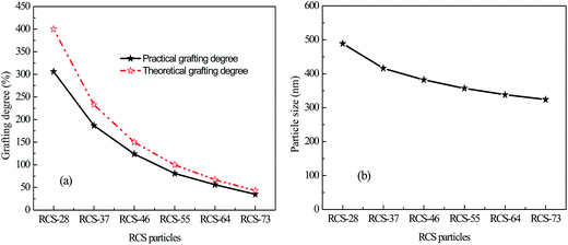
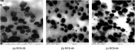
The properties of the RCS particles, such as particle size, grafting degree and morphology, have a very important influence on the toughening behavior. The particle size of the PB used in this work was 296 nm. According to Bucknall’s investigation, the particle size of the rubber can influence its caviation ability and for many high performance blends, the optimum particle size appears to be about 300 nm.29,30 So in the present work, the rubber core size of the RCS particles was a very suitable way to toughen PBT/PC blends. As seen from Fig. 1b, with the increase of the core–shell ratio from 20/80 to 70/30, the particle size of the RCS particles decreased from 489 nm to 324 nm. This decrease of the particle size for the RCS particles can be explained by Fig. 1a, which shows the curves of the theoretical and practical grafting degree of the shell phase of the RCS particles. It can be found that the two curves are different and that part of the shell monomers have not reacted with the PB rubber core. The grafting degree of the RCS particles decreased from 306% to 35% when the core–shell ratio changed from 20/80 to 70/30. So the higher shell monomer content can induce much more grafted shell polymers on the PB phase and lead to a bigger RCS particle size. On the other hand, the grafting degree of the RCS particles can influence their dispersed phase morphology and the final mechanical properties of the blends, which will be discussed in the following section.The obvious difference in the core–shell ratio can also influence the micro morphology of the RCS particles. For the RCS particles, the shell is the MMA-co-St-co-GMA plastic phase which grafts onto the surface of the PB particles and can be called ‘external-grafting’. At the same time, because of swelling of the monomer into the PB rubber particles, the grafting polymerization can take place inside the rubber particles too, which can be called ‘internal-grafting’. So the higher shell monomer content may result in much ‘internal-grafting’. Fig. 2 shows the micro TEM morphology of the RCS particles. The PB particles have been stained black due to a chemical reaction between PB and OsO4. It can be seen that, for the RCS-28, obvious ‘internal-grafting’ exists in the PB core since there are white zones in the black PB particles. However, with the decrease of shell monomer content in the RCS particles, ‘internal-grafting’ becomes undistinct, such as for RCS-46 and RCS-64. The ‘external-grafting’ affects the dispersion of the rubber particles in the matrix, and ‘internal-grafting’ can influence the elastic property of the particles. The change in the micro morphology of the RCS particles will also influence the toughening ability of the RCS particles.
Dispersed phase morphology
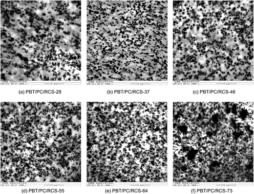
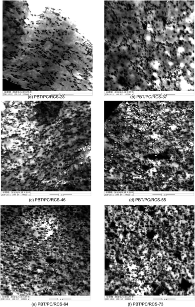
The dispersed phase morphology of the RCS particles is another important factor which can affect the mechanical properties of PBT/PC blends. Fig. 3 shows the TEM morphology of the RCS blends. As for the core–shell particle, the grafting degree and the compatibility between the shell phase and the matrix will determine the dispersed phase morphology. In the present work, the MMA-co-St-co-GMA copolymer shell has good compatibility with the PBT/PC matrix as expected in the introduction. The physical and chemical interactions between the MMA-co-St-co-GMA copolymer shell and PBT/PC are conductive to the dispersion. The influence of the grafting degree on the dispersion of the core–shell particles has been studied by Hasegawa et al. in detail.31 They pointed out that, at a low grafting degree, the polymer grafted particles could not form a stable colloid because the particles were not covered completely with grafted chains. On the other hand, the rubber particles also could not form a stable colloid at a high grafting degree, as the matrix chains were expelled from the grafted chains. There was an optimum grafting degree for dispersing particles in polymer melts. Thus an agglomerated or a three-dimensional network structure of rubber particles formed when the grafting degree of the particles was not in the intermediate region. As can be seen from Fig. 3, RCS-28 forms some agglomeration phases, which indicates that the grafting degree of 306% is too high. As for RCS-73, much larger agglomeration phases can be found, so the grafting degree of 35% is too low for the particle. When the grafting degree is between 56% and 187%, the RCS particles show a much better dispersed phase morphology.In PBT/PC/RCS blends, the matrix includes PBT and PC phases. The miscibility between PBT and PC has been investigated widely.32–35 Different conclusions on the miscibility behavior of PBT/PC blends have been reported, which ranged from complete immiscibility when casted from the common solvents to partial miscibility when melt blended. The complex behavior is due to liquid–liquid phase separation, crystallization of the PBT phase and transesterification reactions. Now, it is commonly accepted that PBT and PC are partially miscible when used in melt blends due to transesterification. Since PBT and PC are partially miscible, it is necessary to show the position of the RCS particles in the blends. In Fig. 4, the samples had been stained with ruthenium tetroxide, to make the PC appear darker against a lighter PBT phase. Since the PMMA components in the grafting shell have good miscibility with the PC phase and the epoxy groups of GMA can react with the carboxyl groups of PBT, the RCS particles may locate in the PC phase, the PBT phase or the interface between the PBT and PC phases. As can be seen from Fig. 4, a small quantity of RCS-28 particles exist in the PC phase and most of the RCS-28 particles disperse in the PBT phase and the interface. As for the RCS-37, RCS-46, RCS-55 and RCS-64 particles, most of the particles disperse in the dark PC phase and form the PC encapsulated structure. In Fig. 4f, obvious agglomeration of RCS-73 takes place and the agglomerated particles are surrounded by the PC phase. So from Fig. 4, it can be concluded that PBT and PC are thermodynamically immiscible. The minor phase domain size of PC in the blends also proves the compatibilization effect of the RCS particles for the PBT/PC blends.
Mechanical properties
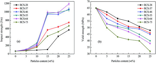
Fig. 5a shows the influence of the RCS content on the Izod notched impact strength of the PBT/PC/RCS blends. The RCS particles with different core–shell ratios display different toughening abilities. For the PBT/PC/RCS-28 blends, the brittle–ductile transition takes place when the RCS-28 content is between 15–20 wt%. RCS-28 shows the worst toughening efficiency compared to the other particles due to its lower rubber content, poor dispersion and bad cavitation ability. RCS-37 has a much better toughening ability than RCS-28 and when the RCS-37 content is 10–15 wt%, the brittle–ductile transition occurs. With an increase in core–shell ratio, all of the blends have the same brittle–ductile transition. RCS-46, RCS-55 and RCS-64 show an excellent toughening ability and the impact toughness of the PBT/PC blend is improved more than 15 times. However, further increase of the core–shell ratio induces a decrease in the toughening ability, such as with RCS-73, due to the poor dispersed phase morphology. Fig. 5b shows the influence of the RCS content on the yield strength of the PBT/PC/RCS blends. The yield strength of the blends decreases significantly with the increase in RCS content. The decrease of the yield strength is due to the elastomeric nature of the PB rubber phase in the RCS particles. From a comparison it can be found that, at the same RCS content, the RCS particles with a higher core–shell ratio reduce the stiffness of the PBT/PC blends much more significantly due to the higher PB content. So according to the impact and tensile results, too high a core–shell ratio is not necessary to achieve superior toughness and more importantly, it can decrease the stiffness of the materials. In the present work, RCS particles with a core–shell ratio of 4/6 show the optimum toughness and stiffness balance for the PBT/PC blends. A similar strategy can be applied to other core–shell particle-toughened polymer blends.Toughening mechanisms
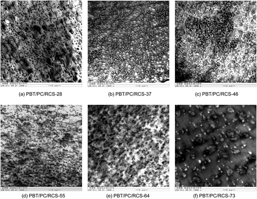
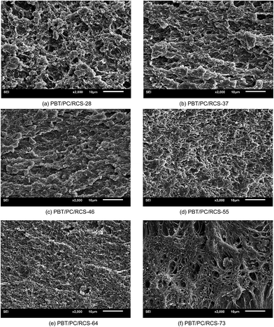
Fig. 6 displays the notched impact fracture SEM morphology of the PBT/PC/RCS blends. The content of the RCS particles in the samples was 20 wt%. As expected, all the fracture surfaces of the PBT/PC/RCS blends show the characteristics of ductile fracture. Obvious plastic deformation can be found on the fracture surface, which implies that shear yielding of the PBT/PC matrix has taken place. Shear yielding is the main energy absorption pathway and promotes improvement in the toughness. In Fig. 6a–e, the interface between the RCS particles and the matrix is obscure, which testifies to the fine interfacial interaction between the matrix and the dispersed phase. However, Fig. 6f shows a much clearer interface and aggregated RCS-73 particles, which further proves the presence of poor interfacial properties between RCS-73 and PBT/PC blends.To correlate the different impact toughnesses of the blends with the internal deformation mechanisms, TEM was used to observe the deformation zone under the impact fracture surface. Void formation plays a key role in rubber toughening. Until the rubber particles have cavitated, constraints on shear yielding remain very high in the plane strain region. To obtain enhanced levels of toughness, the blend must be capable of developing cavitation and producing shear yielding. Fig. 7 shows the different deformation morphologies of the PBT/PC/RCS blends. The content of the RCS particles in the samples was 20 wt%. From Fig. 7a, no cavitation appears in the RCS-28 particles. The reason lies in the low core–shell ratio inducing a high grafting degree and ‘internal grafting’, which decease the elastic property and the cavitation ability of RCS-28 particles. So the PBT/PC/RCS-28 blend displays a much higher brittle–ductile transition and lower impact toughness than the other blends. In Fig. 7b, some voids can be found which indicate that cavitation of the RCS-37 particles has taken place. However, due to the relatively low core–shell ratio, ‘internal grafting’ also decreases the cavitation ability of RCS-37. So the number of cavitated particles is small and the impact toughness of the PBT/PC/RCS-37 blend is not very high. In Fig. 7c–e, a lot of the RCS particles have cavitated, which can promote extensive shear yielding of the matrix and induce the superior impact toughness of the PBT/PC/RCS blends. As for the PBT/PC/RCS-73 blend, cavitation also takes place, but the agglomeration of the RCS-73 particles limits the toughness. So the deformation mechanisms are cavitation of the RCS rubber particles and shear yielding of the PBT/PC matrix. The grafting degree, micro morphology and particle dispersion of the RCS can influence the cavitation and shear yielding, which lead to the different mechanical properties of the PBT/PC/RCS blends.
DMA analysis
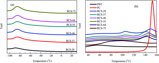
The curves in Fig. 8 show the variation in tan![[thin space (1/6-em)]](https://www.rsc.org/images/entities/char_2009.gif) δ for the PBT/PC/RCS blends as a function of temperature, with different core–shell ratios of the RCS particles. The content of the RCS particles in the samples was 20 wt%. As can be seen, the peaks near −89 °C, 57 °C, 105 °C and 150 °C belong to the Tg of PB, PBT, MMA-co-St-co-GMA and PC respectively. The DMA results also show that PBT and PC are thermodynamically immiscible due to the two separate Tg peaks. From comparison it can be found that the Tg of the PB phase almost does not change through the variation of the core–shell ratio. However, the Tg peaks of the PBT and PC phases are close to each other and, especially for the PBT/PC/RCS-73 blend, only a wide peak exists in the high temperature zone. So the change in the RCS core–shell ratio not only affects the interaction between the shell phase and the matrix but also influences the interaction between the PBT and PC phases. A detailed explanation will be provided in another paper.
δ for the PBT/PC/RCS blends as a function of temperature, with different core–shell ratios of the RCS particles. The content of the RCS particles in the samples was 20 wt%. As can be seen, the peaks near −89 °C, 57 °C, 105 °C and 150 °C belong to the Tg of PB, PBT, MMA-co-St-co-GMA and PC respectively. The DMA results also show that PBT and PC are thermodynamically immiscible due to the two separate Tg peaks. From comparison it can be found that the Tg of the PB phase almost does not change through the variation of the core–shell ratio. However, the Tg peaks of the PBT and PC phases are close to each other and, especially for the PBT/PC/RCS-73 blend, only a wide peak exists in the high temperature zone. So the change in the RCS core–shell ratio not only affects the interaction between the shell phase and the matrix but also influences the interaction between the PBT and PC phases. A detailed explanation will be provided in another paper.
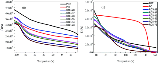
Fig. 9 shows the variation in storage modulus for the PBT/PC/RCS blends as a function of temperature, with different core–shell ratios of the RCS particles. As can be seen from Fig. 9, a lower core–shell ratio of the RCS particles induces a higher storage modulus of PBT/PC/RCS blends. So DMA results also prove that a low core–shell ratio for the RCS particles is beneficial for improvement of the stiffness of the PBT/PC blends.
Conclusions
Modification of the core–shell ratio provides an effective way to prepare core–shell particle-toughened polymer blends with a superior toughness and stiffness balance. The change in the core–shell ratio affected the grafting degree, micro morphology and dispersion of the RCS particles which influenced the final mechanical properties of the PBT/PC/RCS blends. Deformation results proved that cavitation of the PB rubber particles and shear yielding of the PBT/PC matrix were the major toughening mechanisms. The ‘internal grafting’ restrained the cavitation ability of PB and decreased the toughening efficiency of the RCS particles, which induced a higher brittle–ductile transition for the PBT/PC blends. The higher core–shell ratio induced a lower grafting degree and could lead to agglomeration of the RCS particles, which also reduced the mechanical properties of the blends. DMA and TEM results showed that PBT and PC were thermodynamically immiscible. The optimum toughness and stiffness balance for the blends was obtained by changing the core–shell ratio of the RCS particles and a similar approach could be applied for other core–shell particle-toughened polymer blends.Acknowledgements
This work was financially supported by the National Natural Science Foundation of China and Jilin Provincial Science & Technology Department under grants 51273025, 50803007 and 20140101104JC.References
- D. R. Paul and C. B. Bucknall, in Polymer Blends:Formulation, Wiley-Interscience Publication, New York, 2000 Search PubMed.
- L. A. Utracki, in Polymer Blends Handbook, Kluwer Academic Publishers, Netherlands, 2002 Search PubMed.
- I. Aravind, K. J. Eichhorn, H. Komber, D. Jehnichen, N. E. Zafeiropoulos, K. H. Ahn, Y. Grohens, M. Stamm and S. Thomas, J. Phys. Chem. B, 2009, 113, 1569–1578 CrossRef CAS PubMed.
- A. M. Adam, Polym. Bull., 2012, 69, 1053–1071 CrossRef.
- S. S. Pesetskii, O. V. Filimonov, V. N. Koval and V. V. Golubovich, eXPRESS Polym. Lett., 2009, 3, 606–614 CrossRef CAS.
- G. Montaudo, C. Puglisi and F. Samperi, Macromolecules, 1998, 31, 650–661 CrossRef CAS.
- S. D. Kim, S. Chakravarti and J. Tian, Polymer, 2010, 51, 2199–2206 CrossRef CAS PubMed.
- E. El Shafee, H. F. Naguib, L. F. Li, S. C. Jiang and L. J. An, Polym. Eng. Sci., 2010, 50, 1036–1046 CAS.
- A. K. Kalkar, H. W. Siesler, F. Pfeifer and S. A. Wadekar, Polymer, 2003, 44, 7251–7264 CrossRef CAS PubMed.
- M. S. Kalhoro, B. J. Gabrys, W. Zajac, S. M. King and D. G. Peiffer, Polymer, 2001, 42, 1679–1690 CrossRef CAS.
- R. M. Kooshki, I. Ghasemi, M. Karrabi and H. Azizi, J. Vinyl Addit. Technol., 2013, 19, 203–212 CrossRef CAS.
- S. L. Sun, F. F. Zhang, Y. Fu, C. Zhou and H. X. Zhang, J. Macromol. Sci., Part B: Phys., 2013, 52, 861–872 CrossRef CAS.
- R. Sonnier, A. Viretto, A. Taguet and J. M. Lopez-Cuesta, J. Appl. Polym. Sci., 2012, 125, 3148–3158 CrossRef CAS.
- C. H. Lei and D. H. Chen, J. Appl. Polym. Sci., 2008, 109, 1099–1104 CrossRef CAS.
- W. S. DePolo and D. G. Baird, Polym. Compos., 2009, 30, 188–199 CrossRef CAS.
- H. Y. Bai, Y. Zhang, Y. X. Zhang, X. F. Zhang and W. Zhou, Polym. Test., 2005, 24, 235–240 CrossRef CAS PubMed.
- H. Y. Bai, Y. Zhang, Y. X. Zhang, X. F. Zhang and W. Zhou, J. Appl. Polym. Sci., 2006, 101, 54–62 CrossRef CAS.
- K. Wang, J. S. Wu and H. M. Zeng, Compos. Sci. Technol., 2001, 61, 1529–1538 CrossRef CAS.
- W. T. W. Tseng and J. S. Lee, J. Appl. Polym. Sci., 2000, 76, 1280–1284 CrossRef CAS.
- J. S. Wu, Y. W. Mai and A. F. Yee, J. Mater. Sci., 2000, 35, 307–315 CrossRef CAS.
- D. Shi, E. W. Liu, T. Y. Tan, H. C. Shi, T. Jiang, Y. K. Yang, S. F. Luan, J. H. Yin, Y. W. Mai and R. K. Y. Li, RSC Adv., 2013, 3, 21563–21569 RSC.
- L. Corte, V. Rebizant, G. Hochstetter, F. Tournilhac and L. Leibler, Macromolecules, 2006, 39, 9365–9374 CrossRef CAS.
- Z. Ke, D. Shi, J. H. Yin, R. K. Y. Li and Y. W. Mai, Macromolecules, 2008, 41, 7264–7267 CrossRef CAS.
- Y. Fu, H. H. Song, C. Zhou, H. X. Zhang and S. L. Sun, Polym. Bull., 2013, 70, 1853–1862 CrossRef CAS PubMed.
- S. Siengchin and J. Karger-Kocsis, J. Appl. Polym. Sci., 2012, 123, 897–902 CrossRef CAS.
- L. A. Utracki, J. Polym. Sci., Part B: Polym. Phys., 2004, 42, 2909–2915 CrossRef CAS.
- S. L. Sun, X. Y. Xu, H. D. Yang and H. X. Zhang, Polymer, 2005, 46, 7632–7643 CrossRef CAS PubMed.
- S. Sun, Z. Tan, M. Zhang, H. Yang and H. Zhang, Polym. Int., 2006, 55, 834–842 CrossRef CAS.
- C. B. Bucknall and D. R. Paul, Polymer, 2013, 54, 320–329 CrossRef CAS PubMed.
- C. B. Bucknall and D. R. Paul, Polymer, 2009, 50, 5539–5548 CrossRef CAS PubMed.
- R. Hasegawa, Y. Aoki and M. Doi, Macromolecules, 1996, 29, 6656–6662 CrossRef CAS.
- P. Marchese, A. Celli and M. Fiorini, J. Polym. Sci., Part B: Polym. Phys., 2004, 42, 2821–2832 CrossRef CAS.
- G. Pompe and L. Haubler, J. Polym. Sci., Part B: Polym. Phys., 1997, 35, 2161–2168 CrossRef CAS.
- A. N. Wilkinson, S. B. Tattum and A. J. Ryan, Polymer, 1997, 38, 1923–1928 CrossRef.
- M. Giorgio, P. Concetto and S. Filippo, Macromolecules, 1998, 31, 650–661 CrossRef.
| This journal is © The Royal Society of Chemistry 2014 |


