
 Open Access Article
 This Open Access Article is licensed under a
 Creative Commons Attribution 3.0 Unported Licence
The utility of dimolybdenum tetrakis(μ-isovalerate) and tetrakis(μ-pivalate) in the stereochemical studies of various transparent compounds†
Magdalena
Jawiczuk
,
Joanna E.
Rode
,
Agata
Suszczyńska
,
Adam
Szugajew‡
and
Jadwiga
Frelek
*
Institute of Organic Chemistry, Polish Academy of Sciences, Kasprzaka 44/52, 01-224 Warsaw, Poland. E-mail: jadwiga.frelek@icho.edu.pl; Web: http://ww2.icho.edu.pl/Frelek_group/index.html Tel: +48-22-343-22-15
First published on 2nd September 2014
Abstract
The aim of the present work was to verify the usefulness of dimolybdenum tetrakis(μ-pivalate) and tetrakis(μ-isovalerate) as auxiliary chromophores for determining the absolute configuration of optically active vic-diamines, vic-amino alcohols, α-amino and α-hydroxy acids by means of electronic circular dichroism (ECD). To this end, a series of measurements designed to check the dependence of ECD and UV-Vis spectra on time and concentration was carried out. The experimental results were supported by a separate set of detailed DFT calculations. The results obtained allowed us to determine the most probable structure of dominating chiral complexes formed in situ in solution for all ligands studied.
1. Introduction
The progress of techniques in determining absolute configuration (AC) was driven by increased attention to chiral molecules. The connection between the stereochemistry of such compounds and their physical, chemical and biological properties has led to further exploration of methods for determining the three-dimensional structure. Chiroptical spectroscopy has been successfully applied for solving stereochemical problems, and has proven to be a sensitive, fast and useful technique. Nowadays, it is generally accepted that use of at least two different chiroptical techniques (ECD, VCD, VROA) in tandem with quantum-chemical calculations is the safest way to unambiguously assign the AC of the compounds tested.1 However, there will always be some compounds whose stereochemistry cannot be unequivocally attributed despite the use of several different spectroscopic methods. Therefore, it is essential to explore new chiroptical methods in order to achieve a greater number of techniques,2 allowing the use of several of them to more reliably determine the AC.1The assignment of AC of molecules transparent in the UV-Vis range by electronic circular dichroism (ECD) requires their transformation into chromophoric derivatives. For such compounds the exciton chirality method (ECCD) has found broad applicability, due to the very characteristic shape of the CD bands, large Cotton effects (CEs) and its non-empirical character.3 However, some conformationally flexible molecules and acyclic compounds may cause difficulties in case of this method, or the rules established do not have general applicability.4–6 On the contrary, the dimolybdenum methodology avoids this problem, since in the chiral Mo2-complexes formed in situ the conformational mobility of ligands is restricted due to steric hindrance from the remaining carboxylate groups of the stock complex.7 This means that mixing the chiral ligand with an achiral auxiliary chromophore, in this case one of the dimolybdenum complexes, results in conformationally defined derivatives. Thus, as an additional benefit, this in situ method allows the determination of the AC of an examined compound based on the ECD spectra alone.8
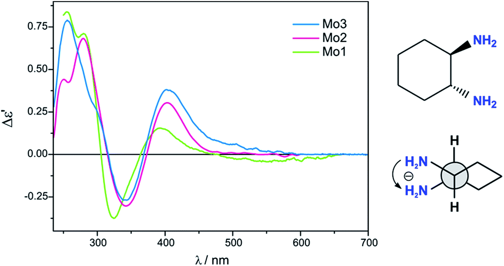
Previous studies have shown that dimolybdenum tetrakis(μ-acetate) (Mo1) can be used as the auxiliary chromophore, as it creates optically active complexes with a wide group of transparent compounds (Fig. 1).9,10 The drawback, however, of using Mo1 is that it has a narrow group of solvents (DMSO, pyridine and acetic acid) in which it can be used, limiting the ability to further study the chiral structures of the analysed molecules. This limitation caused us to search for a viable alternative for dimolybdenum tetrakis(μ-acetate) (Mo1). We examined the usefulness of various dimolybdenum tetracarboxylates in identifying the AC of vic-diols, and compared them to the results with Mo1.11
 | ||
| Fig. 1 Structure of investigated dimolybdenum tetracarboxylates. | ||
Based on preliminary results,11 dimolybdenum tetrakis(μ-pivalate) (Mo2) and dimolybdenum tetrakis(μ-isovalerate) (Mo3) were selected from a variety of dimolybdenum carboxylates as the most promising (Fig. 1). They are well soluble in most common solvents used in spectroscopy as, e.g., hexane, acetonitrile, chloroform, and ethanol. The results for both these complexes with vic-diols were similar to those for Mo1. Considering the intensity and the sign sequence of CEs these auxiliary chromophores are subject to the same helicity rule proposed previously for dimolybdenum tetrakis(μ-acetate).11 This rule correlates the positive sign of CE around the 300 nm in the ECD spectra with a positive sign of the OH–C–C–OH torsion angle of the diol unit.7,12–15 In addition, through experimental measurements and computational tools, the probable structure of the dominant chiral complex existing in the solution was shown to be chelated rather than bridging.11
Since the two complexes, i.e.Mo2 and Mo3, were successful with the vic-diols we began to wonder – could they be also applied in dichroic studies for other important transparent ligands such as 1,2-diamines, 1,2-amino alcohols, α- and β-hydroxy acids or α-amino acids? These classes of ligands are of particular importance due to their interesting properties as well as their role in pharmacy,16,17 as building blocks in synthesis,18 in the cosmetic industry19 or by the production of polymers.20,21 Moreover, compounds such as α-amino acids, α- and β-hydroxy acids play an important role in the functioning of the human body, for example β-hydroxy acids serve as an energy source when blood sugar is low.22
In the present study both dimolybdenum tetrakis(μ-pivalate) and dimolybdenum tetrakis(μ-isovalerate) complexes were used in the analysis of the above mentioned groups of compounds and confronted with Mo1, as a test of their suitability. Model compounds of known AC will be examined to confirm correlation between structure and CEs in ECD spectra, subsequently allowing the application of these rules to compounds of unknown AC.
Furthermore, ECD calculations were conducted and compared with the experimental results in order to establish the structure of the dominating chiral complex created in the solution.
In the context of the above, the main objective of this work can be defined as a test of the suitability of the two dimolybdenum tetracarboxylates Mo2 and Mo3 as auxiliary chromophores in dichroic assignment of AC for a variety of biologically important compounds, non-absorbing in the UV-Vis spectral range. We intend to achieve this goal by examining the kinetic stability of the chiral complexes formed in solution. In addition, we will test the dependence of the shape of CD curves on the concentration ratio of ligand to stock complex. A notable result of the study is establishing the extent of applicability and potential restrictions in the use of complexes in question as auxiliary chromophores in dichroic studies.
2. Results and discussion
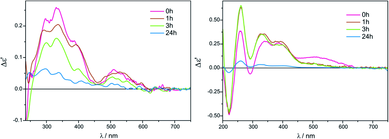
We began our inquiry by measuring the ECD spectra for each of the studied ligands under different measurement conditions in order to establish the best one. The conditions varied in terms of ligand-to-metal complex molar ratio, solvent and time. Based on our previous experience with vic-diols we noticed that the ratio of ligand to metal between 1.5 and 3 to 1 gave the best results, and so we decided to take advantage of this range of concentrations in our current work.11 Since the solvent can cause significant differences in the spectra, the experimental measurements were performed in chloroform and acetonitrile. This choice is also in accord with our previous experience with solvents for dimolybdenum complexes.11 Samples were measured after dissolving of components, then 1, 3 and 24 hours after, to examine the stability of the chiral complexes formed in situ in the solution. After initial optimization of measurement conditions and selection of the best solvent, the study of generality, sensitivity, and reliability of complexes Mo2 and Mo3 as auxiliary chromophores in ECD measurements of their adducts with α-amino- and α-hydroxy acids, 1,2-amino alcohols and 1,2-diamines were conducted. The results of our considerations will be presented for each type of ligands individually.I. α-Amino acids
The ECD measurements of α-amino acids chosen as models for present studies (Chart 1) were conducted in a mixture of acetonitrile and water at a ratio 4 to 1 to overcome the low solubility of the substrates without the addition of water. The other solvent, i.e. chloroform, was completely excluded because of the total insolubility of the ligands. As a model compound for study of concentration dependence and time stability of the complexes formed in situ in solution L-valine (1) was chosen. | ||
| Chart 1 Investigated α-amino acid ligands. | ||
Because the general shape of ECD curves is unchanged for both concentrations of ligand versus stock complex, i.e. 1.5![[thin space (1/6-em)]](https://www.rsc.org/images/entities/char_2009.gif) :1 and 3:1, for either Mo2 or for Mo3, we decided to carry out the measurements with lower concentration for economic reasons. The chiral complexes formed in situ were stable within the examined time period, or a slight decrease in the intensity of bands in the diagnostic spectrum range ∼300−450 nm was observed, as presented in Fig. 2 and S1 in ESI†. Summarising, we conducted the experiments with the remaining α-amino acid ligands under optimised conditions, namely in 1.5:1 ligand-to-stock complex molar ratio, and after the dissolution of constituents in a mixture of acetonitrile with water 4:1.
:1 and 3:1, for either Mo2 or for Mo3, we decided to carry out the measurements with lower concentration for economic reasons. The chiral complexes formed in situ were stable within the examined time period, or a slight decrease in the intensity of bands in the diagnostic spectrum range ∼300−450 nm was observed, as presented in Fig. 2 and S1 in ESI†. Summarising, we conducted the experiments with the remaining α-amino acid ligands under optimised conditions, namely in 1.5:1 ligand-to-stock complex molar ratio, and after the dissolution of constituents in a mixture of acetonitrile with water 4:1.
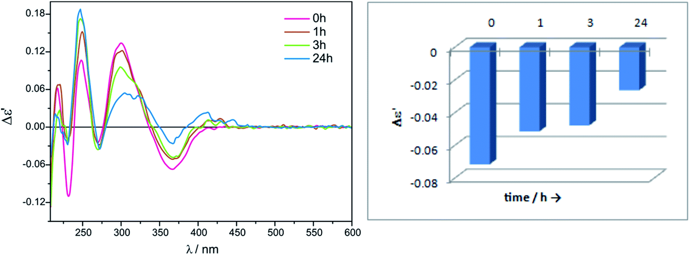 | ||
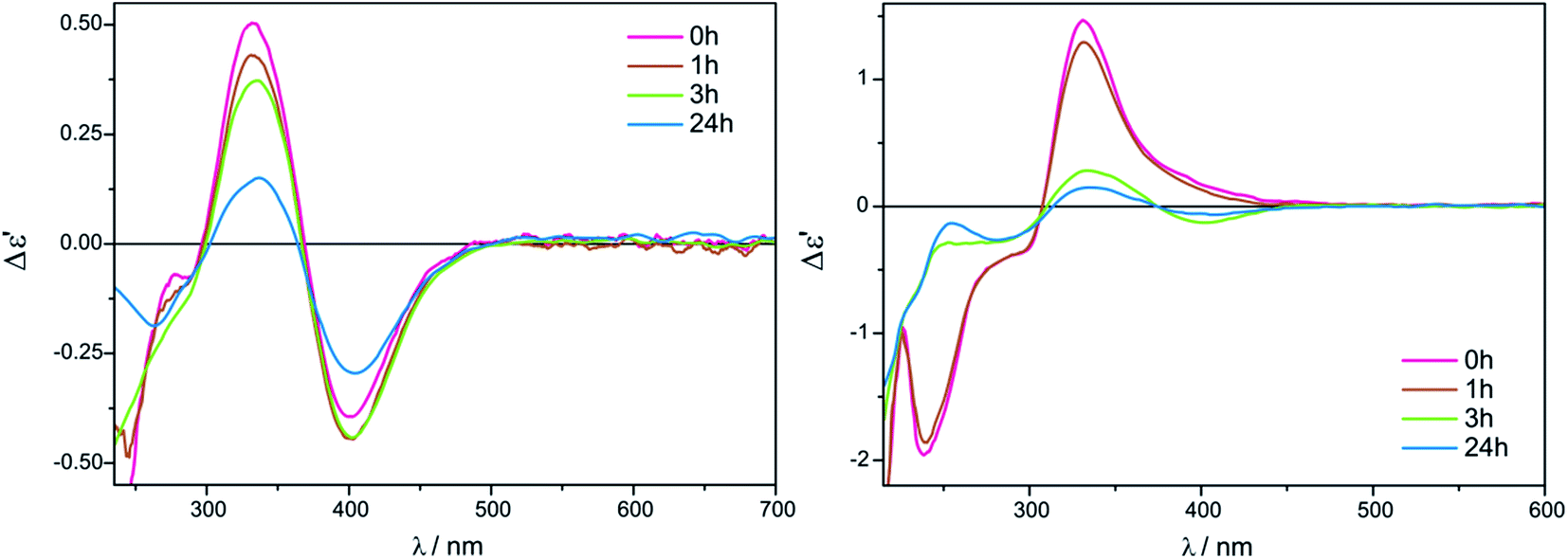
| Fig. 2 Time-dependent ECD spectra of in situ formed Mo2-complexes of L-valine (1) with Mo3 recorded in acetonitrile/water 4:1 ratio (left); Graphical presentation of time dependence of the ECD spectra of the L-valine (1) complex with Mo2-core at λ = 366.5 nm (right). The term Δε′ is explained in the Experimental section. | ||
In the absorption spectra of stock complexes Mo2 and Mo3 three absorption bands are present. The first one, of weak intensity and occurring at ca. 440 nm (band B), is assigned to the δ → δ* transition whereas the more intense absorption band appearing at around 300 nm (band A) is attributed to the π → π* electronic transition.23 The third absorption band, present as a shoulder at longer wavelengths of band A and assigned to the δ → π* transition, occurs at ∼325 nm.23 However, in the spectra of adducts resulting from coordination of the various amino acids ligands to Mo2 and Mo3 practically only one absorption band is visible, namely band A (Table 1). On the other hand, in the range of 240–420 nm examined α-amino acids (Chart 1) give from two to four CEs with Mo2 and Mo3 (Table 1). For determining the absolute configuration, the most suitable bands are those near 300 and 370 nm because they are present in the spectra of all α-amino acids tested (Fig. 3 and Table 1).
:1 ratio immediately after dissolvinga
| Comp. | UV ε (λmax) | ECD Δε′ (λmax) | |||
|---|---|---|---|---|---|
| Band A | Band I | Band II | Band III | Band IV | |
| a Values are given as Δε′ (dm3 mol−1 cm−1) and λmax (nm). | |||||
| Mo2 | |||||
| 1 | 4440 (293.5) | +0.06 (248.5) | −0.01 (272.5) | +0.04 (299.0) | −0.03 (367.0) |
| 2 | 5730 (296.0) | — | +0.05 (264.5) | −0.06 (300.0) | +0.04 (372.0) |
| 3 | 4530 (298.5) | — | — | −0.19 (298.0) | +0.01 (369.0) |
|
|||||
| Mo3 | |||||
| 1 | 4540 (293.5) | +0.11 (248.5) | −0.02 (270.0) | +0.13 (300.5) | −0.07 (366.5) |
| 2 | 4850 (293.0) | −0.01 (248.5) | +0.08 (268.5) | −0.02 (308.0) | +0.05 (362.5) |
| 3 | 4590 (292.0) | — | — | −0.19 (293.0) | +0.06 (382.5) |
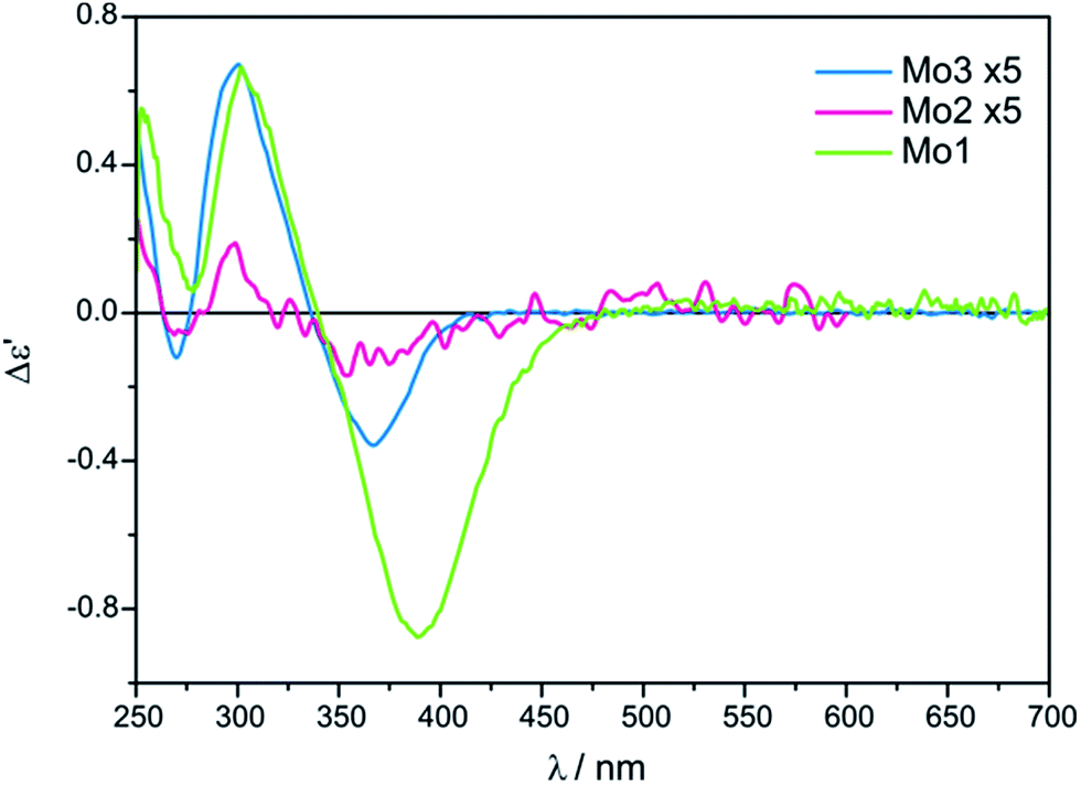 | ||
| Fig. 3 Comparison of ECD spectra of in situ formed chiral complexes of Mo2 and Mo3 with L-valine (1) recorded in CH3CN/H2O (4:1) versusMo1 with 1 recorded in DMSO. The term Δε′ is explained in the Experimental section. | ||
The conclusive CEs for L-α-amino acids at around 370 and 300 nm are negative and positive respectively. Accordingly, the inverse signs sequence in the same spectral range applies to their D counterparts. Thus, the results obtained for Mo2 and Mo3 confirm that they are subject to the same correlating rule as Mo1 (Fig. 3).10
Despite the bands of dimolybdenum tetrakis(μ-pivalate) Mo2 and tetrakis(μ-isovalerate) Mo3 with all tested α-amino acids exhibiting the same CE sign sequence, they are generally less intensive than those of dimolybdenum tetraacetate Mo1. Moreover, due to the poorly developed bands and their very low intensity, Mo2 does not constitute a viable alternative auxiliary chromophore for this group of ligands (Fig. 3). On the contrary, Mo3 can be considered as an alternative to Mo1 because the diagnostic bands are well developed although their lower intensity.
II. α-Hydroxy acids
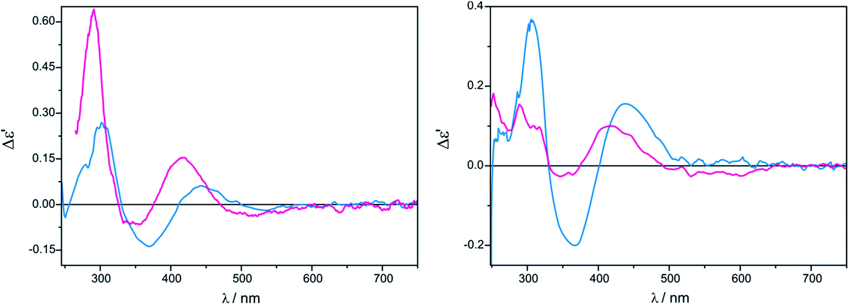
The measurement conditions for the next group of ligands, i.e. α-hydroxy acids presented on Chart 2, were maintained as for α-amino acids, with the exception that both acetonitrile and chloroform were used as solvents. | ||
| Chart 2 Investigated α-hydroxy acid ligands; 4 = L-mandelic acid, ent-4 = D-mandelic acid. | ||
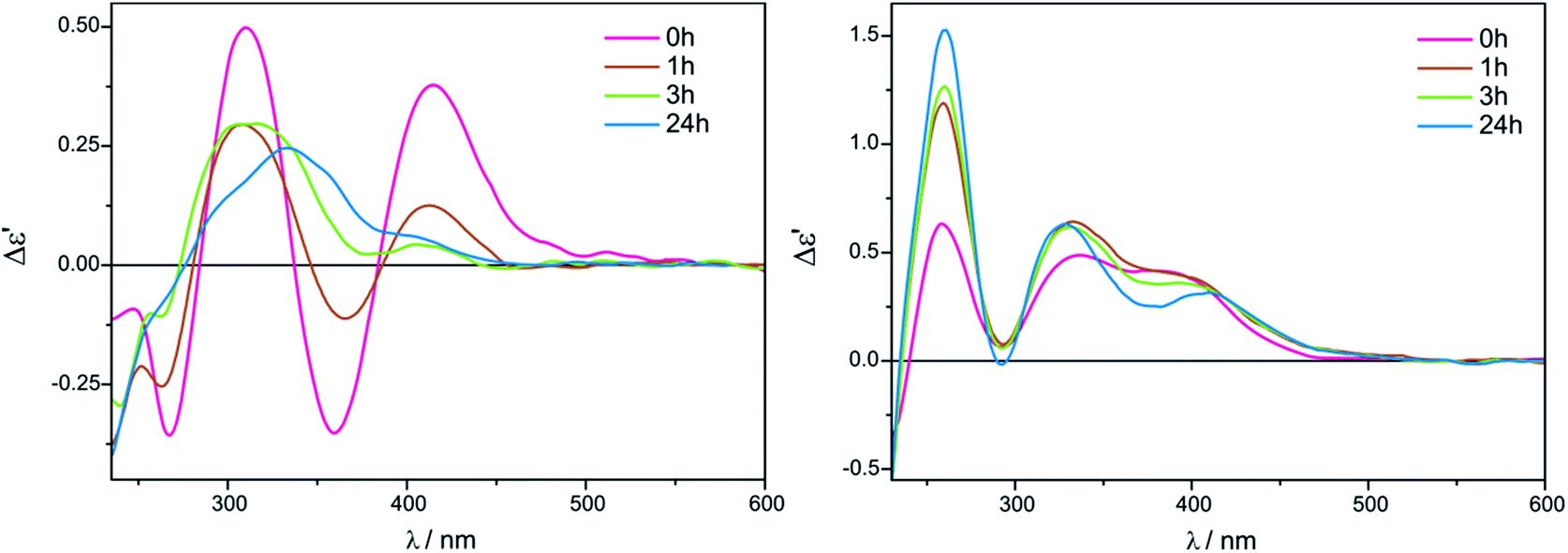
The ECD bands at 330 nm and 400 nm for Mo2 (Fig. S2 in ESI†) and Mo3 in acetonitrile are fully resolved and clearly visible. Moreover, in this solvent, the intensity of ECD bands changes insignificantly with time for both examined auxiliary chromophores, which can be seen in the case of Mo2-complexes of L-lactic acid (5) in Fig. 4 (left).
 | ||
| Fig. 4 Time-dependent ECD measurements of in situ formed Mo2-complexes of L-lactic acid (5) with Mo3 in CH3CN (left) and in CHCl3 (right) in 1.5:1 ligand-to-metal molar ratio. The term Δε′ is explained in the Experimental section. | ||
On the other hand, in chloroform as a solvent, ECD bands at around 410 nm are very poorly developed and overlap in the diagnostic spectral range. In addition, in chloroform the CD pattern and the intensity of bands changed quite significantly during the investigated 24 hours (Fig. 4, right).
To establish whether the shape of CD curves depends on the concentration ratio, the CD spectra of L-lactic acid (5), L-mandelic acid (4) and R-butyric acid (6) with the Mo2-core in 1.5:1 and 3:1 ligand-to-metal ratios were recorded. The results show that increasing the concentration of the ligand does not change the ECD curve or cause a significant change in the intensity of the corresponding CEs (Fig. 5).
 | ||
| Fig. 5 Concentration dependency for L-lactic acid (row 1), L-mandelic acid (row 2) and R-butyric acid (row 3) with Mo2 (A) and Mo3 (B) complex for ECD band IV, i.e. at ∼360 nm; 1.5:1 ligand-to-complex molar ratio (blue), 3:1 ratio (red) recorded immediately after mixing of components. The term Δε′ is explained in the Experimental section. | ||
On the basis of the results presented above it was concluded that the 1.5:1 molar ratio of the constituents is convenient for chiroptical study of α-hydroxy acids. Moreover, ECD measurements can be conducted immediately after chiral complex formation. In order to avoid misleading interpretation caused by changing ECD bands in chloroform for this class of compounds it is recommended to use acetonitrile as a solvent of choice.
In most cases, α-hydroxy acids yield up to four CEs in the range of 230–650 nm with Mo3, and up to five with Mo2. The most intense and therefore the most suitable bands to determine the AC at the α carbon of the α-hydroxy acids appear in the spectral range between 400 and 330 nm, see Fig. 4 (left) and Table 2.
| Comp. | UV ε (λmax) | ECD Δε (λmax) | |||||
|---|---|---|---|---|---|---|---|
| Band A | Band I | Band II | Band III | Band IV | Band V | Band VI | |
| a Values are given as Δε′ (dm3 mol−1 cm−1) and λmax (nm); sh inflection point, a local maximum. b Developed after 24 h. | |||||||
| Mo2 | |||||||
| 4 | 4470 (304.0) | + 0.98 (272.5)sh | — | (335.5)a | +0.52 (390.0) | −0.06 (517.0) | −0.13 (632.0) |
| ent-4 | 4520 (306.0) | −1.29 (270.0)sh | — | +0.03 (336.0) | −0.53 (394.0) | + 0.05 (516.5) | +0.05 (633.0)b |
| 5 | 4590 (306.5) | −0.28 (253.0) | — | −0.24 (320.0) | +0.48 (392.5) | −0.01 (528.5) | — |
| 6 | 5410 (293.0) | +0.73 (233.0) | −0.01 (292.0) | +0.10 (323.0) | −0.35 (394.0) | — | — |
|
|||||||
| Mo3 | |||||||
| 4 | 4660 (303.0) | +1.39 (271.5)sh | — | −0.07 (335.0) | +0.64 (390.0) | −0.02 (524.0) | −0.07 (630.5)b |
| ent-4 | 3750 (304.0) | −1.00 (271.0)sh | — | +0.10 (333.0) | −0.62 (389.0) | +0.05 (524.0) | +0.06 (631.0) |
| 5 | 4740 (303.5) | −0.22 (253.5) | — | −0.26 (330.5) | +0.40 (395.5) | — | — |
| 6 | 1810 (298.0) | +0.43.5 (243.5) | −0.01 (299.0) | +0.06 (335.0) | −0.12 (400.5) | — | — |
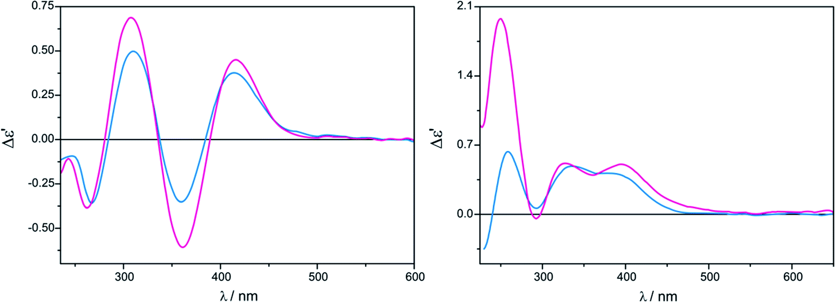
For L-mandelic acid (4), a broad CE at ∼630 nm can be observed in the ECD spectrum (Fig. 6). This band appears right after dissolution for the complex Mo2, while for Mo3 it develops fully after 24 hours. Inversely, the D enantiomer (ent-4) develops this ECD band immediately after reconstitution with Mo3 and overnight for Mo2 (Table 2).
 | ||
| Fig. 6 Comparison of ECD spectra of in situ formed chiral complexes of Mo2–Mo3 with L-mandelic acid (4) recorded in CH3CN versusMo1 with 4 recorded in DMSO. The term Δε′ is explained in the Experimental section. | ||
The ECD spectra of examined ligands (Chart 2) with either dimolybdenum tetracarboxylate Mo2 as well as Mo3 are shifted towards higher energy spectral range compared to spectra recorded with the use of dimolybdenum tetraacetate Mo1 (Fig. 6). From the viewpoint of the relationship between structure and signs of CEs such a shift towards lower energy is undoubtedly an advantage.
Based on the above mentioned results the correlation between the signs of particular CEs and configuration of α-hydroxy acids can be formulated as follows: with Mo2 or Mo3 as auxiliary chromophores, all L-α-hydroxy acids give a positive CE of around 400 nm and a negative one near 330 nm. For D-α-hydroxy acids an opposite sign pattern is observed (Table 2).
In conclusion, both complexes Mo2 and Mo3 display the conformity of signs of individual absorption bands coherent with the operating hexadectant rule10,24 and can be applied as effective replacements of Mo1 (Fig. 6).
III. 1,2-Amino alcohols
Another group of compounds, which were a subject of our investigation are vic-amino alcohols whose selected representatives are depicted in Chart 3. | ||
| Chart 3 Investigated 1,2-amino alcohol ligands; 7 = D-alaninol, ent-7 = L-alaninol. | ||
In the case of tetrakis(μ-pivalate) Mo2 the most intense and fully resolved bands are observed in chloroform for 1.5:1 ligand-to-metal molar ratio (Fig. 7, left). Shifting concentration to 3:1 does not cause changes in the shape of the ECD bands, but induces a small upswing of their intensities (Fig. 7). In acetonitrile the intensity of ECD bands in 300–500 nm energy range changes insignificantly with increased ligand concentration (Fig. 7).
 | ||
| Fig. 7 Concentration dependency for D-alaninol (7) with Mo2 complex recorded in CHCl3 (left) and in CH3CN (right); 1.5:1 ligand-to-complex molar ratio (blue), 3:1 ratio (purple). The term Δε′ is explained in the Experimental section. | ||
The intensity of short-wavelength ECD bands changed slightly over time in acetonitrile. More substantial changes, and some decrease of band intensities was observed during the 24 hours in chloroform, as can be seen in Fig. 8.
 | ||
| Fig. 8 Time-dependency for compound 7 with Mo2 recorded in CHCl3 (left) and in CH3CN (right) for 1.5:1 ligand-to-complex molar ratio. The term Δε′ is explained in the Experimental section. | ||
On the contrary, in the presence of Mo3, well developed CEs occur in acetonitrile (Fig. 9, right), while in chloroform ECD bands are less intense and not entirely resolved (Fig. 9, left). In addition, a similar time and concentration-dependence as for Mo2 can be observed in this case (Fig. S3 in ESI†).
 | ||
| Fig. 9 Time dependency for compound 7 with Mo3 recorded in CHCl3 (left) and in CH3CN (right) for 1.5:1 ligand-to-complex molar ratio. The term Δε′ is explained in the Experimental section. | ||
In order to avoid misleading interpretation of results, it is recommended that ECD spectra be measured after dissolution with 1.5:1 ligand-to-metal molar ratio in chloroform for Mo2 and acetonitrile for Mo3 as a solvent of choice.
(R)-Propranolol (10) was measured only in CHCl3 in the form of hydrochlorides and in the form of free amine (obtained in situ after addition of a drop of aqueous base to the solution). Similar shape with different intensity of the ECD curves was received in both forms of amine for Mo2 and Mo3 (Fig. 10).
 | ||
| Fig. 10 ECD spectra of in situ formed Mo2-complexes of Mo2 (left) and Mo3 (right) with (R)-propranolol (10) recorded in CHCl3 without (purple line) and with (blue line) a trace of alkali. The term Δε′ is explained in the Experimental section. | ||
ECD band intensity of hydrochloride increases with time, whereas the free amine shows a decrease in 24 hours (ESI Fig. S4–S5†). In the spectra of compound 10, bands around 270−300 nm cannot be seen as they are obscured by own electronic absorptions of 10 in the specified spectral range (ESI Fig. S6†). Results collected in Table 3 demonstrate that the examined 1,2-amino alcohols exhibit up to six CEs in the 250–600 nm spectra range. (Fig. 11). The most suitable for structure-chiroptical properties correlation are the ECD bands occurring in the 300–500 nm spectral range since, being adequately intensive, they occur in the spectra of all model compounds tested.
| Comp. | UV ε (λmax) | ECD Δε (λmax) | ||||
|---|---|---|---|---|---|---|
| Band A | Band I | Band II | Band III | Band IV | Band VI | |
| a Values are given as Δε′ (dm3 mol−1 cm−1) and λmax (nm); a without trace of alkali, b negative maximum, c additional inflection point at ca. 315.0 nm, d additional UV-Vis band at 479.5, e own electronic absorption, f positive minimum, g additional UV-Vis band at 472.5 nm, * due to turbidity of the solution results should be treated as qualitative. | ||||||
| Mo2 | ||||||
| 7 | 6660 (297.0) | −0.30 (267.5) | — | +0.55 (310.0) | −0.30 (359.5) | +0.43 (415.0) |
| ent-7* | 5800 (302.6) | +0.20 (266.5) | — | −0.54 (309.0) | +0.25 (360.0) | −0.38 (414.5) |
| 8 | 7540 (299.0) | −0.90 (269.5) | — | (300.0)b,c | −0.41 (361.5) | +0.29 (418.5) |
| 9 | 5800 (302.0) | +0.14 (264.5) | −0.15 (295.5) | (324.0)b | −0.09 (361.0) | — |
| 10 a | 4560 (331.5)d | — | e | e | −0.07 (354.0) | +0.15 (418.0) |
|
||||||
| Mo3 | ||||||
| 7 | 4490 (308.0) | +0.38 (261.0) | — | −0.06 (292.0) | +0.28 (339.0) | +0.26 (386.0) |
| ent-7* | 4290 (308.0) | −0.38 (258.0) | — | +0.01 (291.5) | −0.28 (338.0) | −0.25 (384.0) |
| 8 | 4900 (302.5) | +0.43 (258.0) | — | (291.0)f | +0.33 (337.0) | +0.33 (397.0) |
| 9 | 4510 (306.5) | −0.07 (260.5) | −0.09 (285.0) | + 0.01 (319.5) | −0.18 (374.5) | +0.06 (455.5) |
| 10 a | 3170 (339.0)g | — | e | e | −0.03 (346.0) | +0.10 (418.5) |
 | ||
| Fig. 11 Comparison of ECD spectra of in situ formed chiral complexes of D-alaninol (7, pink line), L-alaninol (ent-7, blue line) and D-α-phenylglycinol (8, green line) with Mo2 (left) recorded in CHCl3 and with Mo3 (right) recorded in CH3CN. The term Δε′ is explained in the Experimental section. | ||
For Mo3 with vic-amino alcohols, the empirical correlation between signs of particular CEs and the torsional angle N–C–C–O can be formulated as follows: a positive (negative) torsional angle of amino alcohol subunits correlates with a negative (positive) sign of the CE around 300 nm and a positive (negative) of around 340 nm (Fig. 12). Dimolybdenum tetrakis(μ-pivalate) (Mo2) with vic-amino alcohols is the subject to the same regularity as Mo3.
 | ||
| Fig. 12 Comparison of ECD spectra of in situ formed chiral complexes of D-alaninol (7) with Mo2 (in CHCl3) and Mo3 (in CH3CN) versusMo1 with 7 (in DMSO). The term Δε′ is explained in the Experimental section. | ||
The proposed helicity rule is based on the ECD spectra of acyclic vic-amino alcohols of both ephedrine and adrenaline types, complexed with Mo2-core, and it is consistent with the rule proposed previously for Mo1.24 Thus, we are entitled to conclude that the two dimolybdenum tetracarboxylates Mo2 and Mo3 are an efficient alternative to Mo1.
IV. 1,2-Diamines
The last group of examined ligands are vic-diamines presented in Chart 4. Beside dimolybdenum tetrakis(μ-pivalate) Mo2 and tetrakis(μ-isovalerate) Mo3 also dimolybdenum tetrakis(μ-acetate) Mo1 was investigated with this class of compounds as it has not been examined previously. Due to the limited solubility of Mo1 measurements were conducted in DMSO. | ||
| Chart 4 Investigated vic-diamine ligands; 11 = (1S,2S)-DACH, ent-11 = (1R,2R)-DACH. | ||
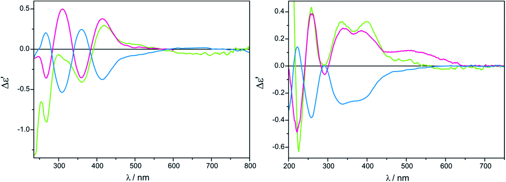
(2S)-3-phenylpropane-1,2-diamine (13) was chosen as a model diamine for preliminary studies on the solubility, stability and the influence of the chiral ligand concentration on the resulting ECD spectra. As before, both acetonitrile and chloroform solvents for Mo2 and Mo3 were tested. For all three complexes Mo1–Mo3 two chiral ligand-to-metal ratios, namely 1.5:1 and 3:1 were checked. Time stability of the complexes formed in situ was examined immediately after mixing of components and after 1, 3 and 24 hours. The result of this research was establishing the optimum measurement conditions for this class of compounds.
As a solvent of choice in this case we recommend to use chloroform as it causes the full development of at least two ECD bands for both complexes Mo2 and Mo3, whereas in acetonitrile in the most suitable range for establishing a correlation, i.e. above 300 nm, only one well resolved CE within a reasonable time is yielded (Fig. 13).
 | ||
| Fig. 13 Time and solvent-dependence ECD measurements of in situ formed Mo2-complexes of compound 13 with Mo3 in CH3CN (right) and in CHCl3 (left) in 1.5:1 ligand-to-metal molar ratio. The term Δε′ is explained in the Experimental section. | ||
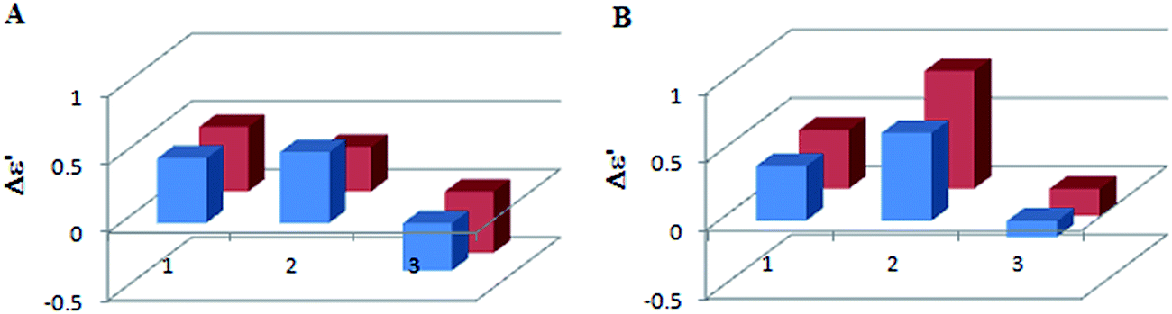
The shape of ECD curves vary within 24 h; for compounds 11, 11-ent, 13 and 14 intensity of the CEs decrease with time, while for 12 they grow for 1.5:1 ligand-to-metal molar ratio (Fig. 14).
 | ||
| Fig. 14 The time-dependent ECD spectra of in situ formed complex of compound 12 with Mo2 (left) and bar charts showing time-dependency for chiral complex formed with Mo3 (right) at λmax = 323 nm recorded in CHCl3 for 1.5:1 ligand-to-complex molar ratio. The term Δε′ is explained in the Experimental section. | ||
As observed, vic-diamines in the salt form cannot be investigated by in situ methodology. However, in the form of free amine (obtained in situ after addition of a drop of aqueous base to the salt solution) ECD study can be performed successfully (Table 4).
| Comp. | UV ε (λmax) | ECD Δε (λmax) | |||||
|---|---|---|---|---|---|---|---|
| Band A | Band B | Band I | Band II | Band III | Band IV | Band V | |
| a Values are given as Δε′ (dm3 mol−1 cm−1) and λmax (nm); sh inflection point, a additional inflection point at 321.5 nm, b negative maximum, c additional negative CD at 284.0nm, d additional positive minimum at 285.0 nm. | |||||||
| Mo1 | |||||||
| 11 | 3500 (295.0) | 412 (385.0) | −0.49 (285.5)sh | — | +0.64 (331.5) | −0.15 (396.0) | +0.04 (452.0) |
| ent-11 | 2190 (295.0) | — | +0.53 (283.0) | — | −0.39 (324.0) | +0.15 (394.5) | +0.02 (450.0)sh |
| 12 | 4600 (303.0) | 177 (434.0) | +0.57 (279.5)sh | — | +4.74 (322.0) | −0.63 (398.5) | +0.32 (494.0) |
| 13 | 5500 (298.0)a | 125 (438.0) | — | — | +0.08 (351.5) | −0.12 (402.0) | − |
| 14 | 5080 (303.0) | 251 (439.0) | +0.05 (297.0) | — | −0.06 (354.5) | — | +0.01 (461.5) |
| 15 | 5420 (299.0) | 383 (437.0) | +1.74 (274.0) | +1.07 (308.5) | — | −1.04 (400.0) | − |
|
|||||||
| Mo2 | |||||||
| 11 | 4590 (296.0) | 820 (456.5) | −0.78 (281.0) | — | +0.28 (342.0) | −0.27 (402.5) | − |
| ent-11 | 4700 (297.0) | 910 (457.0) | +0.68 (279.0) | — | −0.30 (342.0) | +0.30 (403.5) | − |
| 12 | 5260 (296.5) | 795 (449.0) | −0.59 (283.0) | +2.25 (318.0) | +0.72 (348.0)sh | −0.59 (404.5) | − |
| 13 | 4390 (299.0) | 730 (469.0) | −0.12 (290.5) | — | +0.23 (345.5) | −0.19 (409.5) | − |
| 14 | 4670 (297.0) | 663 (466.0) | (286.5)b | −0.24 (307.0) | — | +0.12 (391.0) | + 0.11 (439.0) |
| 15 | 4340 (299.5) | — | +0.99 (293.0)c | −0.24 (333.0) | (343.5)b | −0.57 (387.5) | − |
|
|||||||
| Mo3 | |||||||
| 11 | 4270 (302.0) | 819 (472.5) | −0.67 (260.0) | −0.18 (300.0)sh | +0.22 (340.5) | −0.40 (401.5) | − |
| ent-11 | 4530 (300.0) | 781 (450.0) | + 0.77 (257.0) | +0.24 (300.0)sh | −0.26 (341.0) | +0.40 (403.0) | − |
| 12 | 5280 (300.0) | 700 (438.0) | −0.51 (291.0) | — | +2.35 (323.0) | −1.43 (400.0) | +0.01 (485.0) |
| 13 | 4590 (299.0) | 530 (468.0) | (288.5)b | — | + 0.50 (332.0) | −0.39 (398.5) | − |
| 14 | 4220 (304.5) | — | − | −0.28 (304.5) | — | +0.18 (386.5) | +0.09 (463.0)sh |
| 15 | 6460 (295.0) | 77 (429.0) | +0.95 (291.5)d | — | +0.11 (335.0)sh | −0.69 (386.5) | − |
The stability of the complexes formed in situ with Mo1 was tested on the example of (1R,2R)-diaminocyclohexane (ent-11). As can be seen in Fig. 15 the biggest difference in the intensity of ECD band occurs within the first hour of reconstitution and is not so substantial later on. That is why we decided to measure vic-diamines with dimolybdenum tetrakis(μ-acetate) Mo1 1 h after dissolution of the components.
 | ||
| Fig. 15 Graphical presentation of the time-dependent ECD spectra of in situ formed complex of (1R,2R)-DACH (ent-11) with Mo1 at λmax = 325 nm for 1.5:1 ligand-to-complex molar ratio. The term Δε′ is explained in the Experimental section. | ||
The (S)-(−)-2-aminomethyl-1-ethylpyrrolidine (14), compared to other tested diamines, gives the weakest CEs with all three dimolybdenum complexes (Table 4). This may result from poor complexation of the ligand(s), as the ethyl substituent limits access to the nitrogen atom. Its ECD spectra recorded with Mo2 and Mo3 were shifted towards higher energy spectral range compared to spectra of other diamines (Table 4).
Also, we examined our alternative carboxylates Mo2 and Mo3 with optically active salts of vic-diamine (15). It forms Mo2-complexes very slowly and with low efficiency, however adding a trace of alkali results in rapid development of several intense CEs (Table 4 and Fig. S7 in ESI†).
The most suitable band for the correlation between structure and sign of CEs in the ECD spectra of Mo2-complexes with vic-diamines, occurs at around 340 nm. A positive torsion angle of the diamine subunit N–C–C–N correlates with a positive CE at around 330 and a negative one at ca. 400 nm. For a negative torsion angle of the diamine subunit an inverse relationship is observed. All three complexes Mo1-Mo3 are subject to this regularity (Fig. 16) and therefore can be used interchangeably for chiroptical study of diamines.
 | ||
| Fig. 16 Comparison of ECD spectra of in situ formed chiral complexes of (1R,2R)-DACH (ent-11) with Mo2–Mo3 recorded in CHCl3 and with Mo1 recorded in DMSO. The term Δε′ is explained in the Experimental section. | ||
V. Computational study
The results of ECD measurements allow to specify AC of examined ligands (1,2-aminols, vic-diamines, etc.), but are purely qualitative since the structure of the adducts formed with auxiliary chromophores is unknown. Thus, with a view to answer the question about the nature of complexes formed in situ and the manner of complexation, we took the advantage of the higher extent solubility of dimolybdenum tetrakis(μ-pivalate) Mo2 and tetrakis(μ-isovalerate) Mo3 in solvents commonly used in spectroscopic studies compared to the currently used dimolybdenum tetraacetate Mo1. Numerous attempts to crystallize chiral dimolybdenum complex with all examined ligands were made. Furthermore, conditions developed in Z. Mayer25 and C. A. M. Alfonso26 groups for synthesis and separations of dirhodium carboxylates with α-amino acids were also applied to their molybdenum analogues. Despite our efforts to isolate the chiral adducts from reaction mixture, to synthesize dimolybdenum complex or obtain proper crystals for single crystal X-ray diffraction analysis, we were unable to succeed. For this reason we decided to apply calculations to provide an insight into the structure of the chiral complexes formed in situ in solution.As a model for computational study, the stock dimolybdenum tetrakis(μ-pivalate) complex [Mo2{(O2C2(CH3)3}4] (Mo2) was chosen because of its short side chain compared to the respective μ-isovalerate (Mo3) analogue. Formation of different structural chiral Mo2-complexes with coordinated selected ligands, i.e. α-amino acid, α-hydroxy acid, 1,2-amino alcohol and 1,2-diamine was considered. In the calculations D-α-alanine (2, Ala), L-mandelic acid (4, MA), S-1-amino-2-propanol (9, APol), (1S,2S)-diaminocyclohexane (11, DACH) and 3-phenyl-propane-1,2-diamine (13, PhPDA) were used as chiral ligands. The uniform code name for considered dimolybdenum tetrakis(μ-pivalate) complexes with chiral ligands was applied: it begins with the type of chiral ligand; next – the bridged or chelated (chel) geometry of complexation is indicated; then the number of coordinated ligands (from 1 to 4) is given; and finally, details of the arrangement of ligands (cis, trans, or s from semidissociated) and differences in projection of the hydrogen atoms (by a or b letters) are specified.
The structures were obtained by subsequent replacement of one or more pivalate group(s) in the stock complex by a chiral moiety(ies). The geometry optimizations and thermochemistry calculations were performed by using the hybrid Becke three-parameter Lee–Yang–Parr density functional theory (DFT) B3LYP functional27,28 combined with LANL2DZ basis set and electron core potential29,30 for the molybdenum atoms, and the 6-31+G(d) basis set for C, N, H, O atoms.
For the obtained structures, UV/ECD spectra were calculated with TD-DFT methods computing the first 50 electronic transitions. To this aim B3LYP, and the long range corrected version of B3LYP using the Coulomb-attenuating method CAM-B3LYP31 functionals, combined with 6-311G(d,p) basis set for C, N, H, O atoms, and LanL2DZ with core potential for the Mo atom were applied. CAM-B3LYP provided results superior to those of B3LYP and only its results are shown in the manuscript. This is consistent with the conclusions of other papers in which different functionals were tested for calculating the ECD spectra.32–35 The full UV/ECD TD-DFT/B3LYP data are collected in the ESI† section.
The ECD spectra were simulated by overlapping Gaussian functions for each transition utilizing the SpecDis ver. 1.61 program.36 A Gaussian band-shape was applied with 0.35 eV as a half-height width. All the calculated UV/ECD spectra have been shifted by the value of difference of maximum absorption of the experimental and calculated UV spectra.37
Solvent effects were taken into account for both optimization and UV/ECD spectra calculations employing the integral equation formalism (IEF) version of the polarizable continuum model PCM38,39 and using the dielectric constant for acetonitrile and chloroform equal to 35.688 and 4.7113, respectively. All the calculations were performed by using the Gaussian 09 package of programs.40
A plethora of possible conformers in each group of considered structures is expected due to: (1) arrangements of the chiral ligands bonding type (bridged, chelated, or axial); (2) rotation around the single C–C, N–C or C–N bonds; (3) way of complexation (via hydroxy or amino groups in case of Ala and APol ligands). Therefore, to restrict the number of conformers, some below assumptions were taken into account based either on our previous experience or on the literature data. Per analogy to our previous study on chiral Mo2-complexes formed with vic-diols,11 bridged and chelated (chel) structures were considered. Structures with axial arrangements of the chiral ligands were excluded from further consideration because of very long axial Mo⋯L distances, where L is a ligand. Therefore, the axial bonding to the Mo2(O2CR)4 molecules is always weak. This is in contrast to the strong axial bonding to rhodium, chromium, ruthenium, etc., in Me2(O2CR)4 compounds (Me = transition metal).23
In the calculations of possible chiral Mo2-complexes only gauche conformers with an antiperiplanar orientation of X–C–C–R unit(s) have been taken into account (X = N or O). This results from the fact that in this position the (Mo–X)–C–C–(X–Mo), where X is O or N, the torsional angle of about ±60° is well-suited for the ligation, and bulky R-groups point away from the rest of the complex and tend to avoid the steric interaction with the remaining carboxylate ligands in the stock complex (Fig. 17).
 | ||
| Fig. 17 Conformers of model chiral ligands considered in the calculations. | ||
When choosing conformers for the calculation of α-amino and α-hydroxy acids we took the evidence in published literature relating two possible ways of complexation by this class of ligands into account. The first way involves the exchange of the pivalate group in the starting complex for the chiral ligand, through two oxygen atoms of carboxylate group of the amino acid.23,41–43 Another possibility is complexation via two hydroxy groups when α-hydroxy acids are used, or through hydroxy and amino group in case of α-amino acids.25,26 Such incorporation of a chiral ligand into the metal core causes the disturbance of chromophore D4h symmetry.
Despite the adoption of these assumptions reducing the number of studied systems, the calculations are extremely time-consuming resulting in a total CPU time of ca.350000 hours. Moreover, in each class of compounds only few structures possessing the same number of atoms (and therefore the same number of basis sets) can be compared energetically. In the Table 1 ESI† the mono- and disubstituted bridged and chelating structure energies and population factors based on the ΔG values are gathered. However, the energetic comparisons must be treated with caution and reserve as values obtained at the DFT level are only approximate. Even for ground state flexible main-group compounds much better estimation of energetics can be achieved by including electron correlation effects in a more explicit way, as given in perturbational or post-Hartree–Fock methods,44–46 The theoretical study of transition metal (TM) complexes excited states is significantly more challenging because of more complicated electronic structure of such compounds which involves the d shell of the metal surrounded by ligand with different acceptor/donor properties. Moreover, dimetallic TM systems often have an inherently multi-configurational character47–49 and require theoretical method which deal with dynamic and non-dynamic correlation effects equally well and in principle, multi-configurational methods are preferred for such systems. However, application of such methods is still restricted to small or medium-size systems. Therefore, TD-DFT method is a compromise between accuracy and cost of the calculations.
Last but not least, small HOMO/LUMO energy gaps in the systems studied here probably caused a slow convergence of the optimization procedure, or problems with obtaining the ECD spectra. Thus, the SCF = Fermi converger is the necessary “keyword” to successfully end this type of calculations.
α-Amino acids
Based on the above, we decided to apply ligation only by COOH group in the bridged complexes (Fig. 18 and S8†).23,41–43 This choice seems reasonable due to the formation of hydrogen bond interaction between NH2 and one of oxygen from carboxylic group which stabilize this kind of adducts. | ||
| Fig. 18 Optimized selected structures of bridged D-α-alanine (2) Mo2-complexes. | ||
Calculations indicate that the bridge structures are in good concordance with the experimental spectrum of D-α-alanine (2). Furthermore, the resulting UV-Vis and ECD spectra depend slightly on the number of exchanged carboxylic groups (Fig. 19). Therefore it is difficult to unambiguously judge which bridge complex dominates in the solution. This means that at this stage of research, we cannot precisely say how many pivalate groups have been replaced by carboxylate(s) of amino acids in the predominant complex formed in situ.
 | ||
| Fig. 19 Comparison of the CAM-B3LYP calculated ECD spectra of selected bridged Ala-complexes with experimental data. | ||
We have also performed the calculations of chelated Mo2-amino acid complexes in which both NH2 and COOH groups interact with one of the Mo atoms (Fig. S10†). The Ala-chel-1c monosubstituted complex is stabilized by intermolecular interactions (between the semidissociated pivalate groups and amine group of the chiral ligand). Furthermore, we considered also disubstituted chelated structures. The Ala-chel-2b was structurally analogical to the dirhodium complex presented independently by Frade26et al. and Majer et al.25 The next complex, Ala-chel-2, is related to the previous one, yet binding to the transition metal via two oxygen atoms of the carboxylate unit. However, the behavior of the chelating structures of Mo2-amino acid complexes mismatched the experimental data, (Fig. S11 and S12†) suggesting that the Mo2-core prefers bridge over chelating arrangement of amino acid ligands. In conclusion, we can say that the molybdenum complexes do not undergo the same mechanisms to exchange their achiral ligands as rhodium complexes.
α-Hydroxy acids
Treating the α-hydroxy acids as oxygen analogs of α-amino acids we can assume that they will be subject to the same ligation mode as α-amino acids. In the case of the bridged Mo2-MA complexes (Fig. S14†), broad ECD bands occur with the maximum nearby 600 nm. These bands come from a combined excitation of metal d–d orbitals and d-phenyl ring transitions of the chiral ligand. The calculated ECD spectra for all bridged D-α-mandelic acid (4) complexes (Fig. S15,† left) reflect the experimental negative and positive bands at around 600 and 380 nm, respectively. The third experimental band at 310 nm is not fully-resolved and appears as a local minimum. The calculated ECD spectra of only two structures: MA-bridge-2trans and MA-bridge-3 (Fig. 20) match this band (Fig. 21).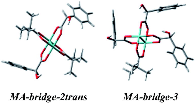 | ||
| Fig. 20 Optimized structures of selected bridged D-α-mandelic acid (4) Mo2-complexes the best matching the experimental ECD spectra. | ||
 | ||
| Fig. 21 Comparison of the CAM-B3LYP calculated ECD spectra of selected bridged MA-complexes with experimental data. | ||
In the diagnostic spectral range between 300–600 nm we observe mismatching behavior of CEs in the simulated spectra of the chelated complexes (Fig. S17†) with respect to experiment (Fig. S15,† right). Therefore, we can conclude that this way of ligation is not favored.
On the basis of the results received for α-hydroxy acids it may be summarized that the bridge structures reproduce the experimental data more precisely and can be considered dominant in the solution, which is consistent with our prediction.
1,2-Amino alcohols
We continue our calculations of dimolybdenum chiral adducts for amino alcohols according to the scheme specified in the general considerations. Complexes of vic-amino alcohols with dirhodium tetraacetate indicated coordination of the chiral ligand to the equatorial position.50 However, formation of equatorial bridged or chelated structures was neither confirmed nor excluded. Initially we thoroughly examined the bridged complexes shown in Fig. S19.† The shape of the simulated curves, obtained for these structures, with one to three coordinated ligand(s), mismatches the experimental data (Fig. S20†).Chelated structures of APol (9) obtained by the optimization procedure are shown in Fig. S23.† Among these structures, there are two with a semidissociated pivalate group. However, after comparing the simulated ECD spectra with the spectrum of S-(−)-1-amino-2-propanol (9) complexes with Mo2 it can be stated that only APol-chel-2 and APol-chel-1s structures (Fig. 22) well reproduced the diagnostic band at around 300 nm (Fig. 23) while it is mismatched by other semidissociated structures (Fig. S24†).
 | ||
| Fig. 22 Optimized structures of selected mono- and disubstituted chelated (chel) S-1-amino-2-propanol (9) Mo2-complexes. | ||
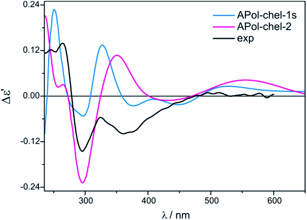 | ||
| Fig. 23 Comparison of the CAM-B3LYP calculated ECD spectra of selected chelated APol-complexes with experimental data. | ||
The CE at 320 nm, which in the experimental spectrum occurs as a local maximum, is reflected in spectra of APol-chel-2 and APol-chel-1s chiral adducts as a well-developed positive ECD band. However, for the former complex this band is shifted ca. 30 nm towards the lower energy spectral range. The next experimental band, however, at 360 nm is only present in the latter complex spectrum. Deeper analysis of the shape of this experimental band suggests that its wideness might be caused by overlapping of another bands of lower intensity or may come from not fully-resolved CEs at 320 and 360 nm.
Such a spectral picture would correspond to the two small-intensity bands calculated for APol-chel-1s, or to broad ECD band of APol-chel-2 shifted to ca. 430 nm. The spectra of other chelated structures exhibit no compliance with the experiment (Fig. S24,† right).
Thus, it seems that the chelated structure is predominant in the solution of vic-amino alcohols, but their type cannot be unequivocally determined from the calculations undertaken.
1,2-Diamines
Two different vic-diamines DACH (11) and PhPDA (13) were considered (Fig. 17) for the simulation of UV-Vis and ECD spectra. For the calculations we adopted both bridging and chelate structure of the adducts. For each of them UV-Vis and ECD spectra were calculated. Next, resulting ECD bands were compared with three CEs appearing in experimental spectra in the 280–410 nm range.Among considered bridged DACH structures (Fig. S27†), the DACH-bridge-1 and DACH-dridge-2-cis-a structures (Fig. 24) reproduced the best two experimental short-wavelength ECD bands (Fig. 25). However, the long-wavelength CE is not reflected by any of bridged DACH adducts (Fig. S28†). Moreover, the shift towards the lower energy field of all ECD bands in simulated spectra of bridged complexes can be seen with increasing number of coordinated chiral ligands to Mo2-core.
 | ||
| Fig. 24 Optimized structures of selected bridged (1S,2S)-diaminocyclohexane (11) Mo2-complexes. | ||
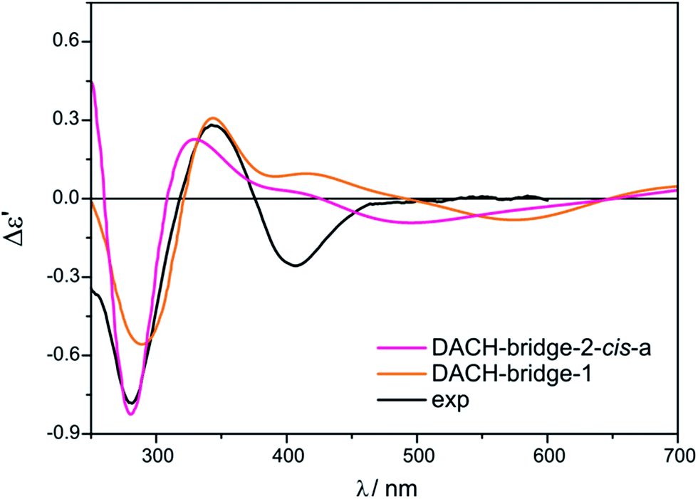 | ||
| Fig. 25 Comparison of the CAM-B3LYP calculated ECD spectra of selected bridged DACH-complexes with experimental data. | ||
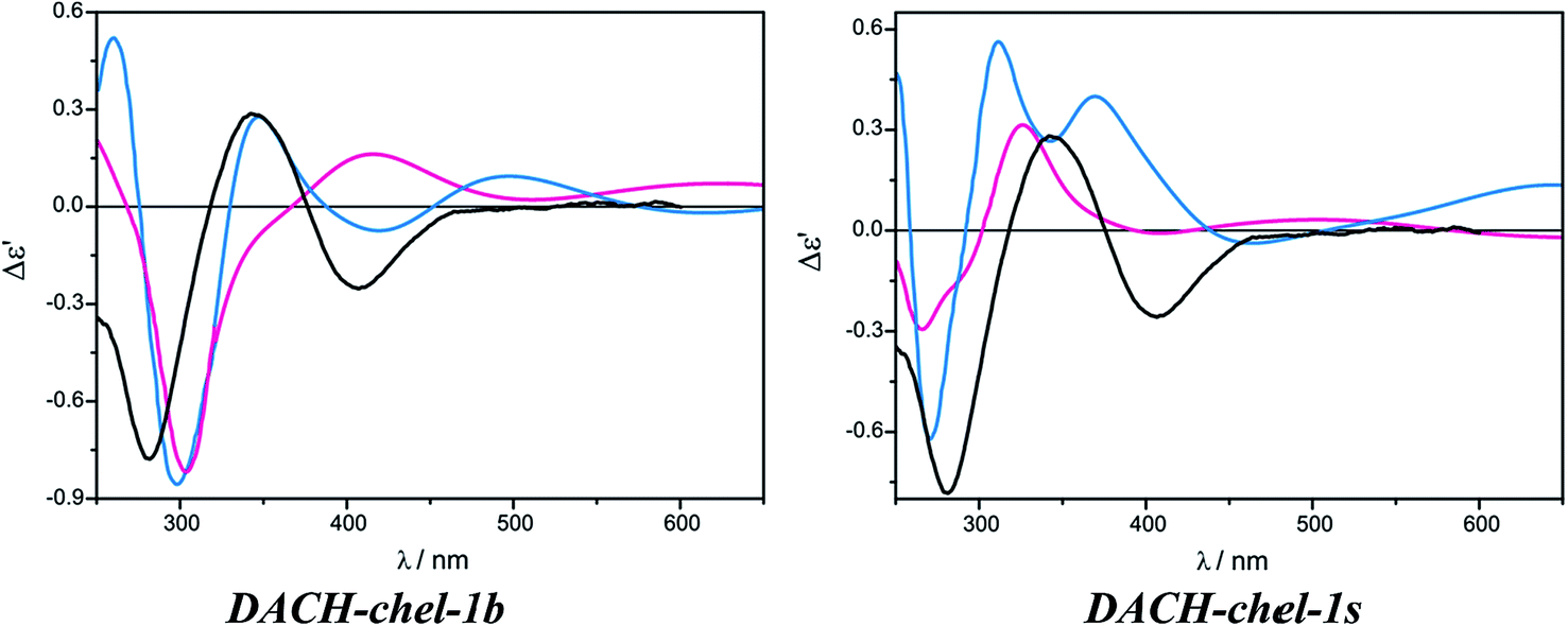
On the other hand, the calculated ECD spectrum of chelated complex DACH-chel-1b (Fig. 26) nicely reproduces all CEs (Fig. 27). Admittedly, the ECD band at around 300 nm is shifted by ca. 25 nm towards lower field compared to experiment, yet the remaining bands fit the measured ECD curve perfectly. In the DACH-chel-1b adduct there are some intermolecular NH⋯O interactions further stabilizing this structure.
 | ||
| Fig. 26 Optimized structures of selected chelated (1S,2S)-diaminocyclohexane (11) Mo2-complexes. | ||
 | ||
| Fig. 27 Comparison of the CAM-B3LYP calculated ECD spectra of selected chelated DACH-complexes with experimental data. | ||
The DACH-chel-1s complex in which the two semidissociated pivalate groups interact with the hydrogens from amino groups of chiral ligands was also taken into account. This type of complexation was postulated to be predominant in the solution of chiral 1,2-diol adducts with dimolybdenum tetrapivalate.11 The ECD calculations for vic-diols were performed with the B3LYP functional, which in the case of DACH–Mo2-complexes studied here, predicts a different shape of the ECD curves than CAM-B3LYP does (Fig. 28). In general, position and sign of only one ECD band (at ca. 290 nm) of chelated complexes is common for both functionals. Moreover, the CE around 400 nm at B3LYP and CAM-B3LYP levels are of opposite signs. Therefore, one must treat the computational ECD results with caution and reserve, and carefully outline the conclusions. So, taking into account the CAM-B3LYP results as more reliable in comparison to B3LYP,32–35 it can be postulated that monosubstituted, chelated hydrogen bonded structures dominate in the solution of DACH with Mo2.
 | ||
| Fig. 28 Comparison of the CAM-B3LYP (blue line) and B3LYP (red line) calculated ECD spectra of chelated DACH-chel-1b (left) and DACH-chel-1s (right) complexes with experiment (black line). | ||
Because of computational problems with the optimization procedure for DACH complexes we decided to run an additional diamine chiral ligand, namely PhPDA (Fig. 17). Similarly to DACH complexes the formation of both bridged and chelated structures was considered and UV-Vis and ECD spectra were calculated at the same level of theory.
Again, for bridged structures (Fig. S32†) the calculated spectra did not exactly reflect the experimental data (Fig. S33†). As for the DACH complexes, only two experimental short-wavelength ECD bands are well reproduced by the PhPDA-bridge-1 and PhPDA-bridge-2-cis-a structures. Calculated ECD spectra of the other bridge structures differ significantly from the experimental spectrum data (Fig. S33†).
On the other hand, among mono- and disubstituted chelating PhPDA complexes (Fig. S36†) the best fit to the measured ECD spectra was obtained for the PhPDA-chel-1 complex as all CEs were predicted with a correct sign (Fig. 29). We also considered the structure with two semidissociated pivalate groups interacting by the hydrogen bonding with amine groups. However, despite the fact that the minimum was localised, its ECD calculations failed without specific cause.
 | ||
| Fig. 29 Comparison of the CAM-B3LYP calculated ECD spectrum of chelated PhPDA-complex with Mo2 (right) with experimental data (left). | ||
Concluding the 1,2-diamines section: the simulated ECD spectra of chelated mono-coordinated dimolybdenum tetrakis(μ-pivalate) complexes are in good concordance with the experimental spectra, which indicates that this type of Mo2-complexes with diamines most likely prevail in the solution.
3. Conclusions
The main finding of the present study is proving the effectiveness of dimolybdenum tetrakis(μ-pivalate) (Mo2) and tetrakis(μ-isovalerate) (Mo3) as auxiliary chromophores. They constitute an alternative to dimolybdenum tetrakis(μ-acetate) (Mo1) which was so far the only chromophore used in dichroic studies of transparent compounds. Their utility in that regard has been confirmed for α-amino and α-hydroxy acids, vic-amino alcohols, and vic-diamines ligands. ECD spectra of in situ formed chiral Mo2-complexes with these ligands allow unambiguous assignment of the AC based on the rules correlating signs of respective CEs with the structure of the investigated ligand. It is worth noting that the correlating rules for Mo2 and Mo3 are the same as those previously formulated for Mo1. The results showed that for the α-amino and α-hydroxy acids a hexadecant rule works efficiently while for vic-amino alcohols and vic-diamines successfully operate a helicity rule. Ultimately, both tested carboxylates serve as auxiliary chromophores equivalent to Mo1.Another essential result of this work is the identification of the probable structure of the dominant chiral complex existing in solution by a combined experimental and theoretical analysis of the ECD spectra. Based on the comparison of these ECD spectra it can be concluded that in the case of α-amino and α-hydroxy acids the bridging mode of ligation dominates in solution. However, in the case of vic-amino alcohols and vic-diamines the chelating mode of binding of ligands to the metal core prevails.
It can be expected that the disclosed in the context of this work effectiveness of the in situ dimolybdenum methodology will affect its broader utilization for determining the absolute configuration of transparent compounds. The simplicity of the methodology consisting of simple mixing a chiral ligand with an achiral auxiliary chromophore is, in fact, its greatest advantage. An additional benefit of the method lies in the possibility for determining the absolute configuration of even flexible molecules on the basis of the ECD spectra alone. This is related to the fact that after bonding to the metal core the internal conformational mobility of such molecules becomes substantially restricted due to the steric requirements of the stock complex.
In our work, we presented new dimolybdenum complexes with greater solubility to act as auxiliary chromophores in the in situ methodologies. Since each method has its benefits and limitations, the expansion of available research methods seems to be essential. As a result of our study, one gains a greater pallet of methods, allowing several parallel techniques to be used.1 This is especially beneficial in doubtful cases, as such an approach allows a high degree of confidence when assigning the absolute stereochemistry of the molecules.
4. Experimental section
The ECD spectra were acquired at room temperature in CHCl3, CH3CN and DMSO (for UV-Spectroscopy, Fluka) on a Jasco J-715 and J-815 spectropolarimeters and were collected at 0.5 nm per step with an integration time of 0.25 s over the range 200–900 nm with 200 nm min−1 scan speed, 5 scans. For the ECD standard measurements the chiral ligands (ca. 0.003 M) was mixed with stock complex [Mo2(O2R3)4] (ca. 0.002 M) and dissolved in respective solvent (5 mL) so that the molar ratio of the stock complex to ligand was about 1:1.5, in general. Using the in situ dimolybdenum method one does not obtain quantitative values since the real complex structure as well as the concentration of the chiral complex formed in solution is not known. Therefore, the ECD data are presented as the Δε′ values. These Δε′ values are calculated in the usual way as Δε′ = ΔA/c × d, where c is the molar concentration of the chiral ligand, assuming 100% complexation (A = absorption; d = path length of the cell).
UV-Vis spectra were measured on a Varian spectrophotometer UV-Vis Carry 100E or on a Jasco V-670 UV-Vis-NIR spectrophotometer in CHCl3, CH3CN and DMSO.
Chiral ligands 1–15 were purchased from Fluka, Sigma-Aldrich, POCH or Alfa-Aesar and were used without further purification.
Acknowledgements
This work is supported by the Ministry of Science and Higher Education, grant no. N N204 187439. Computational grants from Wroclaw Centre for Networking and Supercomputing (WCSS) and Interdisciplinary Centre for Mathematical and Computational Modelling of University of Warsaw (ICM, G19-4) are acknowledged for a generous allotment of computer time. This research was supported in part by PL-Grid Infrastructure. The authors are indebted to PhD Marcin Górecki for fruitful discussion.Literature
- P. L. Polavarapu, Chirality, 2008, 20, 664–672 CrossRef CAS PubMed.
- H.-G. Jeon, M. J. Kim and K.-S. Jeong, Org. Biomol. Chem., 2014, 12, 5464–5468 CAS.
- N. Harada and N. Berova, in Comprehensive Chirality, ed. E. M. Carreira and H. Yamamoto, Elsevier, Amsterdam, 2012, pp. 449–477 Search PubMed.
- K. M. Specht, J. Nam, D. M. Ho, N. Berova, R. K. Kondru, D. N. Beratan, P. Wipf, R. A. Pascal and D. Kahne, J. Am. Chem. Soc., 2001, 123, 8961–8966 CrossRef CAS PubMed.
- H.-G. Kuball, E. Dorr, T. Höfer and O. Türk, Monatsh. Chem., 2005, 136, 289–324 CrossRef CAS PubMed.
- S. Superchi, D. Casarini, A. Laurita, A. Bavoso and C. Rosini, Angew. Chem., Int. Ed., 2001, 40, 451–454 CrossRef CAS.
- M. Górecki, E. Jabłońska, A. Kruszewska, A. Suszczyńska, Z. Urbańczyk-Lipkowska, M. Gerards, J. W. Morzycki, W. J. Szczepek and J. Frelek, J. Org. Chem., 2007, 72, 2906–2916 CrossRef PubMed.
- Z. Pakulski, N. Gajda, M. Jawiczuk, J. Frelek, P. Cmoch and S. Jarosz, Beilstein J. Org. Chem., 2014, 10, 1246–1254 CrossRef CAS PubMed.
- M. Górecki, A. Kamińska, P. Ruśkowska, A. Suszczyńska and J. Frelek, Pol. J. Chem., 2006, 80, 523–534 Search PubMed.
- J. Frelek, M. Górecki, A. Suszczyńska, E. Forro and Z. Majer, Mini-Rev. Org. Chem., 2006, 3, 281–290 CrossRef CAS.
- M. Jawiczuk, M. Górecki, A. Suszczyńska, M. Karchier, J. Jaźwiński and J. Frelek, Inorg. Chem., 2013, 52, 8250–8263 CrossRef CAS PubMed.
- J. Frelek, N. Ikekawa, S. Takatsuto and G. Snatzke, Chirality, 1997, 9, 578–582 CrossRef CAS.
- J. Frelek, G. Snatzke and W. J. Szczepek, J. Anal. Chem., 1993, 345, 683–687 CAS.
- J. Frelek, P. Ruśkowska, A. Suszczyńska, K. Szewczyk, A. Osuch, S. Jarosz and J. Jagodziński, Tetrahedron: Asymmetry, 2008, 19, 1709–1713 CrossRef CAS PubMed.
- J. Frelek, Z. Majer, A. Perkowska, G. Snatzke, I. Vlahov and U. Wagner, Pure Appl. Chem., 1985, 57, 441–451 CrossRef CAS.
- A. Murugan, V. K. Kadambar, S. Bachu, M. Rajashekher Reddy, V. Torlikonda, S. G. Manjunatha, S. Ramasubramanian, S. Nambiar, G. P. Howell and J. Withnall, Tetrahedron Lett., 2012, 53, 5739–5741 CrossRef CAS PubMed.
- K. Steele, P. Shirodaria, M. O'Hare, J. D. Merrett, W. G. Irwin, D. I. H. Simpson and H. Pfister, Br. J. Dermatol., 1988, 118, 537–544 CrossRef CAS PubMed.
- H. U. Blaser, Chem. Rev., 1992, 92, 935–952 CrossRef CAS.
- D. Saint-Léger, J.-L. Lévêque and M. Verschoore, J. Cosmet. Dermatol., 2007, 6, 59–65 CrossRef PubMed.
- S. M. Thombre and B. D. Sarwade, J. Macromol. Sci., Part A: Pure Appl.Chem., 2005, 42, 1299–1315 CrossRef.
- S. L. Bourke and J. Kohn, Adv. Drug Delivery Rev., 2003, 55, 447–466 CrossRef CAS.
- O. E. Owen, A. P. Morgan, H. G. Kemp, J. M. Sullivan, M. G. Herrera and G. F. Cahill Jr, J. Clin. Invest., 1967, 46, 1589–1595 CrossRef CAS PubMed.
- Multiple bond between metal atoms, ed. F. A. Cotton, C. A. Murillo and R. A. Walton, Springer Science and Business Media, Inc, 2005 Search PubMed.
- J. Frelek, A. Klimek and P. Ruśkowska, Curr. Org. Chem., 2003, 7, 1081–1104 CrossRef CAS.
- Z. Majer, G. Szilvágyi, L. Benedek, A. Csámpai, M. Hollósi and E. Vass, Eur. J. Inorg. Chem., 2013, 17, 3020–3027 CrossRef.
- R. F. M. Frade, N. R. Candeias, C. M. M. Duarte, V. André, M. Teresa Duarte, P. M. P. Gois and C. A. M. Afonso, Bioorg. Med. Chem. Lett., 2010, 20, 3413–3415 CrossRef CAS PubMed.
- A. D. Becke, J. Chem. Phys., 1993, 98, 5648–5652 CrossRef CAS PubMed.
- Electronic Density Functional Theory: Recent Progress and New Directions, ed. K. Burke, J. P. Perdew and Y. Wang, Plenum, New York, 1998 Search PubMed.
- P. J. Hay and W. R. Wadt, J. Chem. Phys., 1985, 82, 270–283 CrossRef CAS PubMed.
- P. J. Hay and W. R. Wadt, J. Chem. Phys., 1985, 82, 299–310 CrossRef CAS PubMed.
- T. Yanai, D. P. Tew and N. C. Handy, Chem. Phys. Lett., 2004, 393, 51–57 CrossRef CAS PubMed.
- O. Julínek, V. Setnička, N. Miklášová, M. Putala, K. Ruud and M. Urbanová, J. Phys. Chem. A, 2009, 113, 10717–10725 CrossRef PubMed.
- W. Skomorowski, M. Pecul, P. Sałek and T. Helgaker, J. Chem. Phys., 2007, 127 CrossRef CAS PubMed , 085102/085101–085102/085108.
- X. Li, K. H. Hopmann, J. Hudecová, J. Isaksson, J. Novotná, W. Stensen, V. Andrushchenko, M. Urbanová, J.-S. Svendsen, P. Bouř and K. Ruud, J. Phys. Chem. A, 2013, 117, 1721–1736 CrossRef CAS PubMed.
- R. Kobayashi and R. D. Amos, Chem. Phys. Lett., 2006, 420, 106–109 CrossRef CAS PubMed.
- T. Bruhn, A. Schaumlöffel, Y. Hemberger and G. Bringmann, SpecDis version 1.62, University of Würzburg, Würzburg, Germany, 2014 Search PubMed.
- G. Bringmann, T. A. M. Gulder, M. Reichert and T. Gulder, Chirality, 2008, 20, 628–642 CrossRef CAS PubMed.
- B. Mennucci, Wiley Interdiscip. Rev.: Comput. Mol. Sci., 2012, 2, 386–404 CrossRef CAS.
- G. Scalmani and M. J. Frisch, J. Chem. Phys., 2010, 132 CrossRef CAS PubMed , 114110/114111–114110/114115.
- M. J. Frisch, G. W. Trucks, H. B. Schlegel, G. E. Scuseria, M. A. Robb, J. R. Cheeseman, G. Scalmani, V. Barone, B. Mennucci, G. A. Petersson, H. Nakatsuji, M. Caricato, X. Li, H. P. Hratchian, A. F. Izmaylov, J. Bloino, G. Zheng, J. L. Sonnenberg, M. Hada, M. Ehara, K. Toyota, R. Fukuda, J. Hasegawa, M. Ishida, T. Nakajima, Y. Honda, O. Kitao, H. Nakai, T. Vreven, J. A. Montgomery Jr, J. E. Peralta, F. Ogliaro, M. Bearpark, J. J. Heyd, E. Brothers, K. N. Kudin, V. N. Staroverov, R. Kobayashi, J. Normand, K. Raghavachari, A. Rendell, J. C. Burant, S. S. Iyengar, J. Tomasi, M. Cossi, N. Rega, N. J. Millam, M. Klene, J. E. Knox, J. B. Cross, V. Bakken, C. Adamo, J. Jaramillo, R. Gomperts, R. E. Stratmann, O. Yazyev, A. J. Austin, R. Cammi, C. Pomelli, J. W. Ochterski, R. L. Martin, K. Morokuma, V. G. Zakrzewski, G. A. Voth, P. Salvador, J. J. Dannenberg, S. Dapprich, A. D. Daniels, Ö. Farkas, J. B. Foresman, J. V. Ortiz, J. Cioslowski and D. J. Fox, Gaussian 09, Revision D.01, Gaussian, Inc., Wallingford CT, 2009 Search PubMed.
- F. Apfelbaum-Tibika and A. Bino, Inorg. Chem., 1984, 23, 2902–2905 CrossRef CAS.
- A. Bino and F. A. Cotton, J. Am. Chem. Soc., 1980, 102, 3014–3017 CrossRef CAS.
- F. Apfelbaum and A. Bino, Inorg. Chim. Acta, 1989, 155, 191–195 CrossRef CAS.
- J. C. Dobrowolski, M. H. Jamróz, R. Kołos, J. E. Rode and J. Sadlej, ChemPhysChem, 2007, 8, 1085–1094 CrossRef CAS PubMed.
- J. C. Dobrowolski, M. H. Jamroz, R. Kolos, J. E. Rode, M. K. Cyranski and J. Sadlej, Phys. Chem. Chem. Phys., 2010, 12, 10818–10830 RSC.
- B. Boeckx, W. Nelissen and G. Maes, J. Phys. Chem. A, 2012, 116, 3247–3258 CrossRef CAS PubMed.
- M. Brynda, L. Gagliardi and B. O. Roos, Chem. Phys. Lett., 2009, 471, 1–10 CrossRef CAS PubMed.
- S. J. Tereniak, R. K. Carlson, L. J. Clouston, V. G. Young, E. Bill, R. Maurice, Y.-S. Chen, H. J. Kim, L. Gagliardi and C. C. Lu, J. Am. Chem. Soc., 2013, 136, 1842–1855 CrossRef PubMed.
- D. Escudero and W. Thiel, J. Chem. Phys., 2014, 140 CrossRef CAS PubMed , 194105/194101–194105/194108.
- J. Frelek, M. Górecki, J. Jaźwiński, M. Masnyk, P. Ruśkowska and R. Szmigielski, Tetrahedron: Asymmetry, 2005, 16, 3188–3197 CrossRef CAS PubMed.
Footnotes |
| † Electronic supplementary information (ESI) available: General experimental methods, UV-Vis, ECD spectra for reported compounds, and computational details including all coordinates of calculated structures in txt format. See DOI: 10.1039/c4ra07408d |
| ‡ Present address: Student of Materials Engineering Faculty of the Warsaw University of Technology, Wołoska 141, 02-507 Warsaw, Poland. |
| This journal is © The Royal Society of Chemistry 2014 |