Reticulated three-dimensional network ablative composites for heat shields in thermal protection systems†
Yutika Badhe and
Balasubramanian K*
Department of Materials Engineering, DIAT (DU), Ministry of Defence, Girinagar, Pune, Maharashtra, India. E-mail: yutikabadhe@gmail.com; meetkbs@gmail.com; Fax: +91 020 2438-9509; Tel: +91 020 2438-9680
First published on 29th August 2014
Abstract
Successful utilization of thermosetting resins as ablative materials for heat shields in thermal protection systems (TPS) has newer contemporary materials, surpassing the conventional resins in terms of thermal and physical properties. The present study demonstrates similar progress in ablative heat shielding materials, putting forward capable replacements for existing phenolic system. A novel three-dimensional network composed of a dihydric resorcinol formaldehyde (RF) has been synthesized successfully by modification with boric acid via an effortless and facile polymerization technique. The ablation and thermal properties were investigated with primary and cheap, yet effective test methods like the oxy-acetylene flame test, which explored the ablation rate in terms of mass loss and dimensional change, showing 40% and 70% curtailment respectively. X-Ray diffraction studies confirm the formation of insulative, turbostratic, carbonaceous char formed upon resin pyrolysis with peaks at 24° and 44° attributing to (002) and (100) for turbostratic carbon formed during pyrolysis. FTIR studies reveal change in the intensity and shifts in the peaks for pristine RF for the boric acid modified RF including stretch vibrations at 1429 and 1380 cm−1 corroborating modification of the ring. Atomic Force Microscopy showed the surface roughness which up surged with an increase in the concentration of boric acid in the system, making the composite sensitive to mechanical depletion due to increase reactivity. Interesting morphologies of the sample after ablation were observed with FESEM exposing glassy nanospheres of borate in the periphery and porous char of the depleted zone. Pristine RF has a char yield of 42%, which increased to 68% for 50 wt% of boric acid in RF at 800 °C, quantified by the TGA studies. Mathematical models and energy balance equations were idealized for the exchange in energies at the surface of the ablator. The results determined that the modification of the 3D network of the resin justifies its competency to replace conventional materials demonstrating augmented ablation resistance with faster reaction mechanisms.
1. Introduction
The forebody and payload thermal protection systems of sample return vehicles mandatorily involve the use of ablative materials because of the super orbital re-entry velocities.1 These materials have been used for over 40 years in a broad range of applications to meet the requirements of thermal protection systems (TPS) effectively. Thermal protection systems have been employed in all NASA planetary entry probes, shielding them from the severe heat encountered during hypersonic flight.2 The local pressure and heating rates, combined with erosive forces result in thermal degradation of most ablative materials due to surface temperatures rising to about 2700 °C. The protective asset of an ablative material is a porous carbonaceous char, which is left behind after yielding gaseous products as a consequence of decomposition.3,4 Extending from the virgin material, two basic zones are created at the surface: the char and the developed gases. In the middle area, pyrolysis takes place and hot gases diffuse through the char, consuming energy and continue to react partially blocking the incoming convective heat. Finally, the underlying zone is made of unreacted virgin composite material, which has not been encompassed by heat of any form i.e., convection, conduction or radiation.4,5 The char behaves like an insulation layer, reducing heat flux and gas diffusion from the surface boundary layer to the bulk, thus preserving the unreacted ablator.5,6Major organizations like the Ministry of Defence, India, Nuclear Research Centres and Space research organizations are in a constant pursuit of appropriate low density TPS material candidates, which can withstand prolonged thermal exposure and erosive forces. This has led to the exploration of phenolic resins as ablative composites due to their structural integrity and thermal stability. Despite its erosion resistance and char retention capacity, phenol formaldehyde (PF) has been modified with atoms having high bond energies (boron, molybdenum, titanium and phosphorous),7–12 nanosized inorganic cage structures such as OP-POSS (octa phenol polyhedral oligomeric silsesquioxane),13 thermally resistant hyper branched polyborate (HBPB),14 silicone resin-based anti-ablation coatings,15 nano clay additives in phenolic resin16,17 or changes in the weave patterns of carbon-fabric or silica fibre18,19 to improve its ablation resistance.
Nevertheless, phenol formaldehyde (PF) is not an irreplaceable ablative material. A dihydric phenolic system, resorcinol formaldehyde can readily take its place owing to its high temperature stability and its ability to produce durable adhesive bonds of high strength and excellent weather resistance.20,21 The bonding strength of RF has led to its use as an adhesive for critical joints as well.22 They are a part of thermosetting ablators, also known as non-melting, char forming resins, which possess a high heat of pyrolysis and thus makes suitable matrix materials for ablative composites with enhanced ablation resistance at temperatures above 2800 °C.23 Resorcinol carries a unique molecular structure due to the location of the two hydroxyl groups in the molecule. It gives rise to three reactive sites or positions in the resorcinol molecule for formaldehyde to react. All three reactive positions of resorcinol are doubly activated by the two hydroxyl groups.22 Thus, resorcinol, having two –OH groups in its structure, gives faster reaction rates and has the ability to cure at room temperature, consequently being energy efficient. The reactivity of resorcinol is about twelve times that of phenol with formaldehyde, under similar conditions (assuming phenol has no other substituent on the benzene ring).22,24–26 Conventional phenol formaldehyde, on the other hand, forms bubbles and blisters on the surface if cured without pressures of 15–30 MPa.27,28
The present work has been steered in the direction of dihydric phenolic systems of resorcinol formaldehyde resins by advanced laboratories working for the defence and aerospace sector, supporting the ceaseless continuous development of effective ablative materials for re-entry. The research focuses on critical missions associated with re-entry probes, missile nozzles, wing flanges and ballistic aeroshells in space shuttle programs. These resins, in their pristine form prove to be better ablators than conventional phenol formaldehyde. Furthermore, efforts have been made towards modifying a novel three-dimensional resorcinol formaldehyde (RF) resin structure with boron using a facile route, with simple boric acid in various concentrations and studying their effects and thermal resistance properties. Extensive work has been performed, which describes the synthesis and applications of boron-modified phenolic resin29–31 giving good heat resistance and mechanical properties, but the present work explores modification of a novel resorcinol formaldehyde resin by boron for ablative applications. The effectiveness of the borates as flame-retardants in various materials has been explained by the formation of non-penetrable glass coatings in these materials upon their thermal degradation. The decomposition and ablation behaviors were quantified using a cheap, though effective oxy-acetylene flame test and thermo-gravimetric analysis (TGA), which led to the formation of glass nano-spheres, investigated via FESEM. The analysis of char formation, surface depletion and the energy balance across the surface of the char was carried using thermal modelling.
2. Experimental work
2.1 Materials
Resorcinol (crystalline, 98% purity), formalin solution (37 wt% formaldehyde in water containing 10–15% methanol as stabilizer) and boric acid (white solid) were obtained from Sigma-Aldrich Chemicals Pvt Ltd. 20 wt% NaOH solution was prepared using sodium hydroxide pellets manufactured and supplied by Merck (India) and de-ionized water. De-ionized water was used for all the experiments and was obtained from a Millipore Milli-Q system.2.2 Synthesis of boron-modified resorcinol formaldehyde
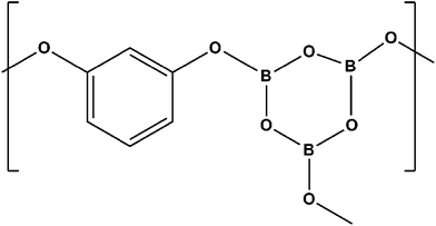
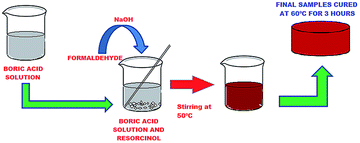
Resole type RF was synthesized via the simple polycondensation of resorcinol and formaldehyde using base catalysis (NaOH) in the presence of a special additive. Boric acid (1, 3, 5, 10, 40, 50 wt%) was first dissolved in boiling water and resorcinol was added slowly to a continuously stirred mixture and the reaction giving a complex product with a network of borate linkages (Fig. 1) carried out at around 120 °C. Formalin was introduced to the mixture attaining a molar ratio of F/R = 2 and 1 ml of 20 wt% NaOH solution added dropwise with constant stirring. The temperature of the system was not allowed to exceed 50 °C. Stirring was performed for 30 minutes until it attained a thick viscous form and the contents transferred to a mould smeared with silicon oil as a mould releasing agent. The mixture was cured and allowed to set in an inert atmosphere in a vacuum oven for about 4 hours at 60 °C. The overall method of synthesis can be represented by Fig. 2. Curing of this structure, leads to the formation of a three-dimensional interconnected network of tailored modified resorcinol formaldehyde resin (Fig. 3). The resins are referred to as one-stage resins since cross-linked products may be made from the initial reaction mixture itself and there is no indispensable need for separate curing agents or hardeners.273. Characterization
3.1 Thermal characterization
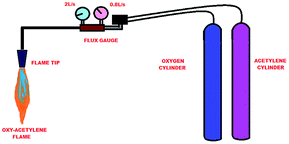
Thermal decomposition studies are generally carried out using thermo-gravimetric analysis. High temperature TGA can be used, which goes up to 1700 °C and can reach temperatures close to the operating temperatures of rocket exhausts. On the other hand, they can reproduce appropriate heating rates, which vary from 5000 °C min−1 to 50![[thin space (1/6-em)]](https://www.rsc.org/images/entities/char_2009.gif) 000 °C min−1.32,33 Nevertheless, practical artificial ablative test conditions, which involve erosive and shear forces, can be imitated using an oxy-acetylene torch flame, according to ASTM E285.28,34,35 It is the most convenient and low cost method, and is used for primary evaluations.36 The test specimen of 40 × 20 mm (D × T dimensions) was fabricated and subjected to the flame for 60 s. The inner diameter of the oxy-acetylene torch tip was 2 mm and a distance of 10 mm was maintained between the torch tip and the sample. Fig. 4 shows a typical setup for an oxy-acetylene flame test. It consists of gas cylinders, flow gauges and a torch. The flow rates of oxygen and acetylene were maintained roughly at 2 L s−1 and 0.8 L s−1, respectively, which generated a flame temperature of around 3000 °C during the test. Although the flame was placed at the center of the sample, the whole area of sample was covered, as a result of formation of flame zones namely the primary flame and reflected flame.37 The ablation characteristics were calculated using the linear ablation rate (LAR) and mass ablation rate (MAR) by observing the weight and thickness changes before and after ablation (eqn (1) and (2)). LAR and MAR can be calculated using the following formulae.38
000 °C min−1.32,33 Nevertheless, practical artificial ablative test conditions, which involve erosive and shear forces, can be imitated using an oxy-acetylene torch flame, according to ASTM E285.28,34,35 It is the most convenient and low cost method, and is used for primary evaluations.36 The test specimen of 40 × 20 mm (D × T dimensions) was fabricated and subjected to the flame for 60 s. The inner diameter of the oxy-acetylene torch tip was 2 mm and a distance of 10 mm was maintained between the torch tip and the sample. Fig. 4 shows a typical setup for an oxy-acetylene flame test. It consists of gas cylinders, flow gauges and a torch. The flow rates of oxygen and acetylene were maintained roughly at 2 L s−1 and 0.8 L s−1, respectively, which generated a flame temperature of around 3000 °C during the test. Although the flame was placed at the center of the sample, the whole area of sample was covered, as a result of formation of flame zones namely the primary flame and reflected flame.37 The ablation characteristics were calculated using the linear ablation rate (LAR) and mass ablation rate (MAR) by observing the weight and thickness changes before and after ablation (eqn (1) and (2)). LAR and MAR can be calculated using the following formulae.38| LAR = dl/dt | (1) |
| MAR = dm/dt | (2) |
The trends in thermal decomposition of the modified resin were followed using TGA on a PerkinElmer Pyris1 TGA (PerkinElmer Inc, USA) and the components quantitatively measured by the weight-loss steps and char residue. About 10 mg of sample was heated in a platinum crucible from room temperature to 800 °C in an argon atmosphere, flow rate of 50 L min−1, with a heating rate of 10 °C min−1 and the change in char residue with concentration was noted. Material degradation is arrested by char formation, which leads to an effective thermal barrier layer.39
3.2 Compositional analysis
Ablated pristine RF and ablated BRF samples were mounted and their patterns recorded on a Bruker AXS D8 Advanced Diffractometer (Bruker Corporation, USA) with Cu Kα radiation from 10° to 80° of 2θ. The change in peaks, signifying combustion and change in composition was analyzed. Functional groups and fingerprints for chemical modification of the RF matrix due to in situ polymerization and modification of RF by boron were identified using FT-IR spectroscopy. The spectra were recorded between 4000 and 500 cm−1 with KBr pellets at room temperature on a PerkinElmer Spectrum BX FT-IR system (PerkinElmer Inc., USA). The FT-IR spectrum was recorded and contrasted for pristine as well as modified RF. Raman spectroscopy was carried out on the sample using the Renishaw in a micro-Raman spectrometer using an argon laser excitation wavelength of 632 nm at 10 mW power with an illumination spot size of 1 μm and acquisition time of 90 s.3.3 Surface morphological analysis
FESEM imaging was adopted on a Carl Zeiss field emission scanning electron microscope (Carl Zeiss AG, Germany) on a 3 mm diameter sample of BRF after ablation. The samples were sputtered using Au–Pd for 75 s in 10 mA under a pressure of 0.6 × 10⁻² Pa and were tested in the microscope at 5 kV; the images were obtained under 22 K× and 50 K×, magnification. The roughness of the specimen was observed using AFM (Asylum research, an oxford instrument company, UK) in tapping mode.4. Results and discussion
4.1 Analysis of the ablation test
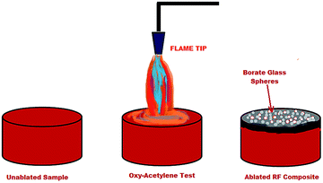
The erosion rate of the matrix during and after ablation depends severely on the integrity and the stability of the char or residue formed.40 The ablation was quantified by calculating the mass ablation rate (MAR) and linear ablation rate (LAR), which assess the mass loss and dimensional changes before and after ablation. The LAR, is given by eqn (1) and MAR by eqn (2). Srikanth et al.'s work on phenol formaldehyde (PF) for ablative applications clearly indicates a MAR of 0.22 g s−1,41 which contrasts strikingly with resorcinol formaldehyde (RF), which is 0.079. A LAR of 0.054 mm s−1 (ref. 42) too has been reported for PF, which is slightly higher than that of RF, which is 0.050. It has been found that both the LAR and MAR curtailed with an increase in concentration of boron. Lower LAR and MAR indicates a lower erosion rate under the dual influence of a hot flame and gas flow. In other words, the materials retain their integrity of structure even at higher temperatures, which plays a crucial role in heat insulation and fire-proofing. Fig. 5 shows the stages of the sample before and after ablation, where it catches fire momentarily and the flame retards immediately. The thermal stability and retardation in thermal conductivity of the char are justified by the formation of borate glass on the surface of the ablated surface, and the chemical modification of the polymeric chain by introducing bonds in the main chains, which have high dissociation energies, like B–O.43Such bonds, along with aromatic ringed structures present in the composite can be termed as physical heat sinks and are responsible for absorbing a major part of the heat supplied. Once the boron is dissociated from the chain in the form of metaboric acid and finally borate,7 the mixture dissolves upon heating in its own water of hydration, froths, and finally fuses to form a glassy surface coating (Fig. 6). These glassy coatings exclude the propagation of oxygen and further prevent combustion,44,45 thereby retarding the extent of pyrolysis in the matrix and as a result, decreases the LAR. Moreover, the amount of porous carbonaceous char increases as ablation progresses,46 and as the access of oxygen towards the inner zones is limited, the material exposed to the flame reduces and hence causes a reduction in the MAR.
Tables 1 and 2 clearly depict the change in weight and dimensions using various concentrations of boric acid, and its effects on the respective ablation rates. The tables also point out the reduction in the ablation rates when compared to pristine RF. Modification of RF with boric acid, in contrast with the addition of SiC, as computed by Yutika et al.,47 has been found to deteriorate marginally in terms of LAR and MAR, though, the low price of boric acid makes it economically a more viable solution. Also, a reduction in the difference between the densities of the matrix and the filler, is higher in the case of SiC, and thus allocates a better molecular level dispersion in the case of boric acid.
| Composition | Weight before Ablation (g) | Weight after ablation (g) | MAR (g s−1) | % Reduction in MAR |
|---|---|---|---|---|
| 1% B + RF | 24.423 | 19.713 | 0.078 | 00.60 |
| 3% B + RF | 24.935 | 20.465 | 0.075 | 05.40 |
| 5% B + RF | 25.330 | 21.070 | 0.071 | 10.10 |
| 10% B + RF | 26.228 | 22.388 | 0.064 | 19.10 |
| 40% B + RF | 29.561 | 26.021 | 0.059 | 25.20 |
| 50% B + RF | 29.832 | 26.952 | 0.048 | 39.30 |
| Composition | Length before ablation (mm) | Length after ablation (mm) | LAR (mm s−1) | % Reduction in LAR |
|---|---|---|---|---|
| 1% B + RF | 20.132 | 17.552 | 0.043 | 14.30 |
| 3% B + RF | 19.897 | 17.439 | 0.041 | 18.50 |
| 5% B + RF | 20.021 | 18.161 | 0.031 | 37.30 |
| 10% B + RF | 20.212 | 19.132 | 0.018 | 63.00 |
| 40% B + RF | 20.145 | 19.246 | 0.015 | 70.00 |
| 50% B + RF | 19.898 | 19.118 | 0.013 | 73.40 |
4.2 X-Ray diffraction pattern analysis
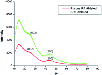
The diffraction patterns of pristine RF and modified RF after ablation were more or less similar with a few distinct differences (Fig. 7). Two broad maxima, corresponding to (002) and (100) reflections of a turbostratic carbon structure, were observed at 2θ angles of about 24° and 44°,48 respectively in carbonized BRF after ablation as well as for pristine RF. The main difference between the spectra can be assayed by an increase in the peak intensity, which proves to be a result of an increase in crystallite height. This inference is in good agreement with those reported in the literature, which explain this change by the electron deficiency of boron with respect to that of carbon, leading to a decrease in repulsive interaction between π-electron clouds of adjacent layers, causing them to come together, thereby minutely increasing the crystallinity of otherwise amorphous carbon.14,48 As the borate glass formed possesses amorphous nature within the resolution limit of XRD, it gives a broad diffused peak at around 20°,49 but it is indefinite due to a dominating carbon peak. The borate glass is capable of retarding the penetration of oxygen at higher temperatures towards the underlying intrinsic layers of the ablator. The flame retardancy of the modified resin is enhanced due to its intumescent properties and the formation of borate glass, which consumes and prohibits oxygen, thereby deferring the advancement of the charred layer further into the matrix.7,144.3 Compositional analysis by FT-IR spectroscopy
The FT-IR spectrum of BRF (Fig. 8) indicates the main bands, in agreement with the bands coming from boron and the alcohol, apart from the major peaks due to the aromatic stretches and absorptions by –CH2– and –OH at 2942, 2842, 1479 cm−1 and 3382 cm−1, respectively. Characteristic bands for alcohol and acids were shown in the region of 3400–3300 cm−1, whereas the band at 1592 cm−1 belongs to the alcohol. Boric acid has a strong and characteristic band at 1480 cm−1 along with bands at 1350 and 1300 cm−1, which also refers to the acid.30 Cross-linked structures are evident from the FT-IR spectra with peaks at 2884 and 1653 cm−1, corresponding to the vibration of C–H in the methylene groups (–CH2–) and C![[double bond, length as m-dash]](https://www.rsc.org/images/entities/char_e001.gif) O bond stretching, respectively.14,50 Peculiar fingerprint regions for the alcohol and acid are seen in the region of 3400–3300 cm−1, while the band at 1592 cm−1 corresponds to the alcohol. A strong band at 1480 cm−1 and the alcohol reciprocates with several bands at 1460, 1443, 1422 and 1417 cm−1. The bands at 1391 and 1336 cm−1 belong only to alcohol, since these bands are not present in the acid, and the bands at 1360 and 1298 cm−1 refer to the B–O bond in the acid.8 As suggested by Liu et al.,51 the band at 1391 cm −1 can be correlated with B–O linkage in borate. An increase in the peak at 750 cm−1 when compared to 810 cm−1 indicates ortho substitution of the rings. Benzene is confirmed from the peaks in the region of 1500–1600 cm−1.51 On the other hand, the peaks at 1429 and 1380 cm−1 were assigned to the stretching vibrations of B–O bonds corresponding to the B–O–Ph structure.52 Hence, it is evident from the overall analysis of the signature peaks that boron successfully modified the thermosetting polymeric resorcinol formaldehyde network.
O bond stretching, respectively.14,50 Peculiar fingerprint regions for the alcohol and acid are seen in the region of 3400–3300 cm−1, while the band at 1592 cm−1 corresponds to the alcohol. A strong band at 1480 cm−1 and the alcohol reciprocates with several bands at 1460, 1443, 1422 and 1417 cm−1. The bands at 1391 and 1336 cm−1 belong only to alcohol, since these bands are not present in the acid, and the bands at 1360 and 1298 cm−1 refer to the B–O bond in the acid.8 As suggested by Liu et al.,51 the band at 1391 cm −1 can be correlated with B–O linkage in borate. An increase in the peak at 750 cm−1 when compared to 810 cm−1 indicates ortho substitution of the rings. Benzene is confirmed from the peaks in the region of 1500–1600 cm−1.51 On the other hand, the peaks at 1429 and 1380 cm−1 were assigned to the stretching vibrations of B–O bonds corresponding to the B–O–Ph structure.52 Hence, it is evident from the overall analysis of the signature peaks that boron successfully modified the thermosetting polymeric resorcinol formaldehyde network.
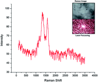
The sample for Raman spectroscopy was prepared using a solution drop casting process. For a full range scan (Fig. 9), two specific absorption peaks for carbonized materials were located within the ranges of 1340–1360 cm−1 (D-mode) and 1580–1600 cm−1 (G-mode), respectively (Fig. 9). The D-mode peaks result from short-range turbostratic structures and the G-mode peak represents the normal graphite structure.53 However, the B–O stretching caused by O–B–O stretching, which is generally observed at 1340 cm−1 and the band at 1160 cm−1 by B–O–B bending54 seems to have been dominated over, by the carbon signatures, falling in the same region. A low range scan was carried out in the range of 200 to 600 cm−1, to detect any low wavelength inorganic signatures, but none were found. Hence, the presence of solely, O–B–O and B–O–B was confirmed by Raman spectroscopy.
4.4 Surface morphology of the ablated BRF
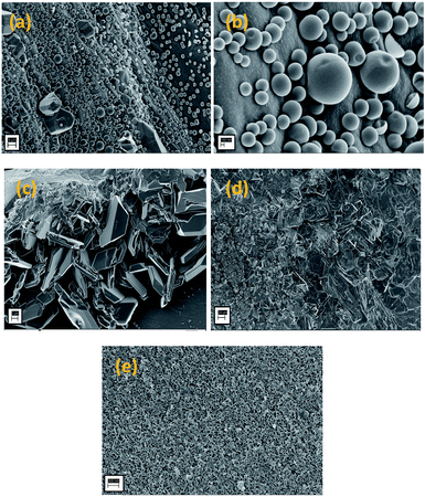
Fig. 10 shows the surface morphologies of the ablated samples of the boron-modified resorcinol formaldehyde, investigated by FESEM. The formation of three different types of morphologies, nano-balloons, nano-blades and porous char, simultaneously is apparent from Fig. 10(a–e). The structures and morphologies are readily distinguishable from each other and co-exist in the matrix without hindering the advent of the other. The formation of the morphologies seen, like nano-balloons, depends on the surface tension of the molten borate glass, which becomes pourable above 500 °C.7,55–57 Fig. 10a and b show a uniform distribution of the nano-balloons over the surface of the periphery ablated composite. On average, the diameter of the balloons ranged from 200–600 nm, whereas a few spheres were found to be of around 1 μm. Moreover, a handful of balloons have been found to be ruptured, and this could be due to the erosive flux of the oxy-acetylene flame. The crystals of borate are recognized instantly, and have a symmetrical morphology along with the nano-blades formed (Fig. 10c and d). The thickness of the blades is not found to exceed a few nm and this could be an important feature for thrust vectoring. A low drag-weight ratio is required for easy flight and sleek, sharp pointed morphologies beneficial for atmospheric penetration.58 The central part of the specimen, where the primary flame is projected, is devoid of any borate morphology. It is found to have a porous char like structure, with evident pores and traces of fused glassy substrate (Fig. 10e). The central part of the specimen was exposed to the highest amount of flux and temperature, and hence, may have caused erosion of the surface material.4.5 Roughness
Fig. 11(a–d) show AFM images of samples with 1%, 5%, 10% and 50% depicting how the surface roughness of the specimen increases with increase in percentage of boric acid. The surface of the sample, as seen by AFM, clearly indicates a nano-spike-like morphology. A spike-like, or pencil-tip-like morphology is the most advantageous for penetrating the atmosphere and as a result, they are capable of tolerating the impact of collision and produce shock waves by causing least damage to themselves.59 Although, higher weight percentages have shown better ablative properties, the char erosion can be reduced by obtaining a smoother surface. A lamellar nano-spike like morphology is seen in all the specimens, and the spike height was seen to vary with the concentration of boric acid. Fig. 11 a shows a low height spiky structure corresponding to a smoother surface. Fig. 11b and c, progressively show taller lamellae, with advancing roughness. Fig. 11d, however, has the maximum percentage of boric acid, and also has uneven random spikes throughout the surface. This morphology is seen to have the maximum erosion in the primary flame region, owing to the higher surface roughness. The literature gives evidence for the fact that a rougher surface is more prone to mechanical erosion. Surface roughness is an inevitable, mundane phenomenon that tends to increase the surface reactivity, promotes turbulent transitions of heat flow causing a spur in the surface recession.60–63 | ||
| Fig. 11 AFM images of (a) 1 wt% boric acid with RF (b) 5 wt% boric acid with RF (c) 10 wt% boric acid with RF (d) 50 wt% boric acid with RF. | ||
4.6 Thermo-gravimetric analysis
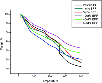
Thermal decomposition traits shown by the thermographs in Fig. 12 depict the change in weight and char residue of the RF during pyrolysis, contrasting it with BRF at different concentrations. Three prominent zones are visible, as the composites follow a two-step degradation process. The first reaction zone (RT – 350 °C) where the evolution of water, unreacted oligomers and small groups such as –CH2OH of the resin matrix are eliminated.64 The first reaction zone also includes the probable formation of additional crosslinking of the unreacted oligomers, along with the evolution of water while forming intermolecular linkages.50 In the second stage (350–500 °C), weight loss occurs due to thermal decomposition during pyrolysis and the crosslinks begin to break and disappear. In the third zone, (500–800 °C), the polymer undergoes severe combustion, and degrades, leaving behind carbonaceous char residue. Hence, overall, breaking of the methylene bridges, followed by breaking of the C–C bonds of the phenolic ring65 is responsible for thermal oxidation. TGA thermographs of PF, when compared to RF, show a degradation temperature roughly ranging from 380 to 450 °C,66–74 whereas the degradation onset of RF is at about 525 °C, proving enhanced thermal stability of RF with respect to PF.Though the thermal decomposition in the second stage somewhat grows gradually with composition showing no considerable change in the degradation till 40 wt% of boric acid, the third zone shows the final char residue, which depicts a dramatic increase by almost 21 wt%, i.e. from 42% to 63% char for 50 wt% boric acid. The structure, crosslinking and composition of the resin establishes the char yield. It is evident from the literature that boron containing polymers yield higher char content than their non-boron counterparts.48,75 The turbostratic carbonaceous char is responsible for the thermal stability of the composite. The increase in char yield, has positive effects on the flame retardancy. The char acts as a protective layer, which isolates the virgin, unablated material from the high temperatures. The gaseous decomposition products percolate through the pores and micro cracks of the hot char layer by diffusion and convection. Finally, they undergo heat exchange with the carbonaceous environment and are eventually ejected at high speeds from the surface into the boundary layer. Such ejection of pyrolysis gases interferes with the flow field and so effectively reduces the convective heat flux reaching the body.76
4.7 Mechanism of ablation
A porous, carbonaceous zone is seen to be formed by the pyrolytic degradation of the matrix resin with the motion of the pyrolytic front into the virgin material, as seen in Fig. 13 depicting the erosion mechanism of a charring ablator. The substructure can be seen on the left, extending to the ablating surface. During the pyrolysis process, the pyrolyzing phase of the material, which is the outermost layer, in contact with the outer environment carbonizes and loses mass, producing pyrolysis gases and advances into the materials. A boundary layer of low pressure is created due the hypersonic hot air advent, above the ablation surface. Heat is circulated and dissipated from the boundary layer, away from the surface, leading to potent heat shielding.77 The pore network of the turbostratic char with micro-cracks, allows the gaseous decomposition products, such as hydrogen, ammonia and hydrocarbons to pervade by diffusion. The gases are evicted out at elevated velocities, bearing heat exchange with the surroundings, and escape the surface to the boundary layer. This departure of gases retards the convective flux approaching the material by meddling with the flow field.76The primary flame of oxy-acetylene, where the temperature is highest, shows regional erosion, and borate glass structures on the periphery of the depleted zone (Fig. 14 and 15). The use of borates in enhancing the flame retardancy of polymeric materials was reported early in the twentieth century.78–80 Boric acid and the hydrated inorganic borates have low melting points and nicely fit this scheme of forming glass coatings. Virgin boric acid loses water, changing to metaboric acid and finally to boric oxide and at temperatures ranging from 350–500 °C, B2O3 softens to glass and becomes fluid. Boron containing compounds are found to promote char formation due to chemical and physical processes involving thermal interactions between the alcohol groups.79–82 Boron tends to form high bond energy B–O–Ph bonds, where the Ph is the phenolic ring, here, resorcinol as mentioned earlier. At high temperatures, a complex structure as shown in Fig. 1 is formed. This is true for phenol as well as dihydric phenols like resorcinol and pyrocatechol.83–85 Thus, incorporation of boron complexes, in the 3D structure of the resin is found to increase the thermal efficiency of the resin as boron is found to exert its flame retardant action on polymeric materials at a temperature well below that of the normal pyrolysis of the materials.7
 | ||
| Fig. 14 A schematic of the ablation showing glass spheres and depleted char zone touching the primary flame. | ||
 | ||
| Fig. 15 A schematic representation of the ablation showing erosion and depletion at the centre of the sample. | ||
Furthermore, the pyrolysis mechanism is chemically proposed by tracing the composition changes during the pyrolysis process. The thermal degradation can be speculated as the reaction shown in eqn (3). This overall reaction can be segmented into three stages, which involve the volume and weight changes.86–88
 | (3) |
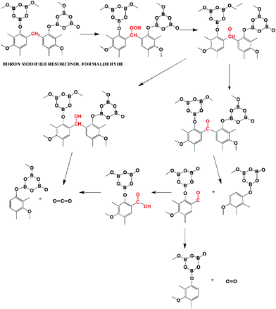
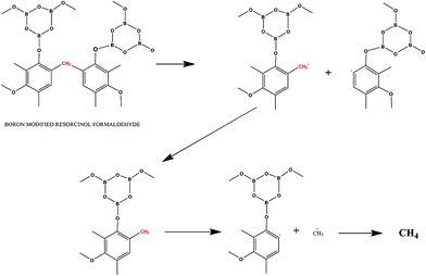
The steps of the two types of degradation mechanisms can be believed to follow the degradation mechanisms similar to that of phenol. A reaction of boron-modified resorcinol formaldehyde, following stepwise degradation of type 1, is shown in Fig. 16. The first step of the thermo-oxidative degradation is the formation of a hydro-peroxide structure followed by decomposition to subsequent structures. According to Knop et al.,76 the methylene bridges are thermodynamically most stable in the structure. The reaction products involve gaseous release of carbon monoxide and carbon dioxide. Another fragmentation reaction, of type 2, can be theorized, which leads to the formation of methane gas (Fig. 17). This type of fragmentation suggests hydrogen abstraction, driving the formation of a large amount of methane above 400 °C. The borate structure attached to the phenolic ring, breaks apart, giving nano-sized borate glass spheres.76,89,90
4.8 Thermal modelling of the ablation of the composites
Thermal modelling of ablative composites in re-entry environments involves extreme convective heating and aero thermal domains.91 While modelling the energy balance along the surface of the composite, adiabatic and impermeable boundary conditions are considered. It is moreover assumed that the heat flow is one dimensional, i.e. occurs only through the thickness of the composite.92 The surface mass balance and surface energy balance are two of the most important criteria to be taken into consideration for precise modelling and correlation.
 | (4) |
This overall energy balance accounts for the total energy balance across the wall under ablative conditions. The first term on the right side reports rate of volatile gas flow across the wall, while the second term takes the effect of heat conduction into consideration. The net rate of energy transfer by convection is determined by the third term and the fourth term accounts for thermal energy that is dissipated or restored by the decomposition reactions.93 This model is in good agreement with the erosion mechanism explained in Section 4.7 (Fig. 12) which depicts the decomposition and erosion at the surface of the ablator. The presence of highly ionized air in the heating region around the surface causes complex pyrolysis reactions at the wall, within the boundary layer.95 The model hence, stipulates the parameters influencing the energy balance and studies the effects of the assumption of local-thermal equilibrium on the decomposition and its overall thermally-induced response. The mass loss, porosity and volumetric expansion of the composite material are some of the relevant parameters that can be determined using eqn (4).93
 | (5) |
Although in terms of energy balance, which includes the effects of surface recession and pyrolysis gases, a thermochemical equilibrium is assumed at the wall and the surface recession is considered. Surface recession of the thickness has detrimental effects on the conduction and thermal capacitance of the virgin material, which lies under the char. This surface recession is formulated using the following equation (eqn (6)).91
 | (6) |
Hence, when looking into the surface of the ablated surface shown in Fig. 13 depicting a greater surface recession or erosion in the central region of the flame, this model is of paramount importance and can be correlated with the alteration in the energy supplied as the flame energy varies over the surface of the matrix. As the heat flux, heating rate and the energy careered towards the material will vary over the surface, there will be a difference in the amount of surface depletion, which is clearly seen at the surface of the composite after the oxy-acetylene flame test.
5. Conclusions
A novel thermosetting resin of RF, having a 3-dimensional structure modified with boron has been successfully synthesized and investigated for potential use as an ablative material in thermal protection systems. Boron-modified RF has been put forward as a replacement for phenol formaldehyde systems with various additives. The high bond energy of B–O bonds and the formation of nano-balloons and nano-blades, lead to easy atmosphere penetration and enhanced ablation behavior. Polymerization of the resin was carried out adopting a facile route in our own laboratory, and thermal investigations and morphological studies were carried out. XRD results vouch for the formation of insulative, turbostratic, carbonaceous char formed upon resin pyrolysis. There was about a 73% reduction in the LAR and 40% in the MAE, quantifying the change in weight and dimensions upon exposure to high thermal flux. Formation of borate glass nano-balloons, drastically thwart the flow of oxygen to the basal virgin material. The porous char favours the passage of the flux of pyrolysis gases and reaction products, which hinders the motion of heat flux, thereby reducing the extent of heat to the material. 50 wt% of Boric acid gave a charge yield of 68%, which was around 26% more than that of pristine RF (42% char yield) at 800 °C. These results substantiate the enhancement of the RF resin as ablators by modification with boric acid, and their capability as materials for thermal protection systems. The incorporation of boric acid leads to a highly functional structure, estimated by the stretch vibrations at 1429 and 1380 cm−1 from FT-IR spectroscopy, is capable of forming a three-dimensional cured resin, which involves a higher heat for dissociation, thereby embellishing the thermal stability. It can be concluded that superior ablative materials can be obtained, by diverging from the conventional phenol formaldehyde resins and exploring effortless modifications for the development of thermal protection systems and heat shields.Acknowledgements
The authors would like to thank Dr Prahlada, Vice Chancellor, DIAT (DU) for their encouragement and support, and the DIAT-DRDO Nano Project Program (EPIPR/1003883/M/01/908/2012/D (R&D)/1416 Dated: 28.03.2012, DRDO HQ, New Delhi for financial assistance. The authors express their sincere gratitude towards Dr Robin McIntyre, Iconiq Innovations, for English language and spelling corrections The authors gratefully acknowledge Dr I. Srikanth and Dr Anil Kumar, Advanced Systems Laboratory, DRDO (Ministry of Defence), Hyderabad, for providing constant support and guidance throughout the course of this investigation. The authors thank Dr A.C Abhyankar (DIAT (DU), Dr Suwarna Datar (DIAT (DU), Dr Prashant Alegaonkar DIAT (DU), Dhananjay Gunjal and Suwarna Raut for their help and support for characterization and Nitin Khare for his crucial help in the oxy-acetylene flame setup.References
- E. Kolawa, T. S. Balint, G. Birur E. Brandon, L. Del Castillo, J. Hall, M. Johnson, R. Kirschman, R. Manvi, M. Mojarradi, A. Moussessian, J. Patel, M. Pauken, C. Peterson, J. Whitacre, E. Martinez, E. Venkatapathy, P. Newdeck and R. Okojie, Technical Report JPL D–32832, National Aeronautical and Space Administration, Washington, D.C., Sept. 2007 Search PubMed.
- R. Palaninathan and S. Bindu, J. Spacecr. Rockets, 2005, 42, 971 CrossRef.
- L. Torre, J. M. Kenny and A. M. Maffezzoli, J. Mater. Sci., 1998, 33, 3137 CrossRef CAS.
- D. W. K. Ho, J. H. Koo and O. A. Ezekoye, J. Spacecr. Rockets, 2009, 46, 526 CrossRef CAS.
- L. Torre, J. M. Kenny and A. M. Maffezzoli, J. Mater. Sci., 1998, 33, 3145 CrossRef CAS.
- L. Torre, J. M. Kenny, G. Boghetich and A. M. Maffezzoli, J. Mater. Sci., 2000, 35, 4563 CrossRef CAS.
- M. O. Abdalla, A. Ludwick and T. Mitchell, Polymer, 2003, 44(24), 7353 CrossRef CAS PubMed.
- A. M. Kawamoto, L. C. Pardini, M. F. Diniz, V. L. Lourenco and M. F. K. Takahashi, J. Aerosp. Technol. Manag, 2010, 2(2), 169 CrossRef CAS , 85.
- H. Yu, J. Liu, X. Wen, Z. Jiang, Y. Wang, L. Wang and J. Zheng, Polymer, 2011, 52(21), 4891 CrossRef CAS PubMed.
- Y. Zhang, S. Shen and Y. Liu, Polym. Degrad. Stab., 2013, 98(2), 514 CrossRef CAS PubMed , 90.
- D. Cho, Phenolic. J. Mater. Sci Lett., 1996, 15, 1786 CrossRef CAS.
- T. L. Dhami, O. P. Bahl and B. R. Awasthy, Carbon, 1995, 33(4), 479 CrossRef CAS.
- S. Kuo, C. Huang and F. Chang, Macromol. Rapid Commun., 2006, 537–541 Search PubMed.
- P. Xu and X. Jing, Polym. Eng. Sci., 2010, 50(7), 1382 CAS.
- J. Xiao, J.-M. Chen, H.-D. Zhou and Q. Zhang, J. Mater. Sci. Eng. A, 2007, 452–453, 23–30 CrossRef PubMed.
- R. D. Patton and C. U. Pittman, Composites, Part A, 2002, 33, 243–251 CrossRef.
- J. H. Koo and L. A. Pilato, 41st AIAA–ASME– SAE–ASEE, Joint Propulsion Conference & Exhibit, Tucson, AZ, 2005 Search PubMed.
- J. K. Park, D. Cho and T. J. Kang, Carbon, 2004, 42, 795 CrossRef CAS PubMed.
- J. T. Mottram and R. Taylor, Compos. Sci. Technol., 1987, 29, 189 CrossRef CAS.
- J. M. Dinwoodie, Wood Adhesives Chemistry and Technology, ed. A. Pizzi, Marcel Dekker, New York, 1983, vol. 1, pp. 1–58 Search PubMed.
- R. E. Kreibich, Wood Adhesives: Present and Future, ed. A. Pizzi, Applied Polymer Symposium, 1984, vol. 40, pp. 1–18 Search PubMed.
- R. Durairaj, Resorcinol, Chemistry, Technology and Applications, Springer-Verlag, Berlin, Heidelberg, Germany, 2005, pp. 180–182 Search PubMed.
- R. P. Nathan and S. Bindu, in Low Temperature Ablative Heat Shield for Re-Entry Vehicles, Proceedings of AIAA thermophysics conference, Ontario, Toronto, Canada, 2005 Search PubMed.
- J. Delmonte, The Tech. Of Adhesives, Reinhold, 1947, ch. 2, p. 26 Search PubMed.
- A. Pizzi, Handbook of Adhesives technology, Chap 29, Ecole Nationale Supérieure des Technologies et Industries du Bois, Université de Nancy I, Epinal, France.
- H. E. Euler, Angew. Chem., 1941, 54, 458 CrossRef CAS PubMed.
- J. A. Brydson, Plastic materials, Butterworth Heinemann, 7th edn, 1999, p. 645 Search PubMed.
- G. Pulci, J. Tirillò, F. Marra, F. Fossati, C. Bartuli and T. Valente, Composites, Part A, 2010, 41, 1483 CrossRef PubMed.
- America Patash Chem Corp., British patent 957611, 1964.
- J. G. Gao, Y. F. Liu and L. T. Yang, Polym. Degrad. Stab., 1999, 63, 19 CrossRef CAS.
- J. G. Gao, Y. F. Liu and F. L. Yang, Eur. Polym. J., 2001, 37, 207 CrossRef CAS.
- J. H. Koo, Polymer nanocomposites: processing, characterization, and applications, McGraw-Hill Professional, 2006 Search PubMed.
- I. Pektas, J. Appl. Polym. Sci., 1998, 68, 1337–1342 CrossRef CAS.
- A. R. Bahramian and M. Kokabi, J. Hazard. Mater., 2009, 166(1), 445–454 CrossRef CAS PubMed.
- E. S. Kim, E. J. Kim, J. H. Shim and J.-S. Yoon, J. Appl. Polym. Sci., 2008, 110, 1263–1270 CrossRef CAS PubMed.
- D. Zhao, C. Zhang, H. Hu and Y. Zhang, Compos. Sci. Technol., 2011, 71, 1392–1396 CrossRef CAS PubMed.
- M. Natali, M. Monti, J. M. Kenny and L. Torre, Composites, Part A, 2011, 42, 1197–1204 CrossRef PubMed.
- Y. Zeng, X. Xiong, G. Li, Z. Chen, W. Sun and D. Wang, Carbon, 2013, 54, 300 CrossRef CAS PubMed.
- P. Sanoj and K. Balasubramanian, J. Compos. Mater., 2014, 825607 Search PubMed.
- J. Wang, N. Jiang and H. Jiang, Int. J. Adhes. Adhes., 2009, 29(7), 718 CrossRef CAS PubMed , 15.
- I. Srikanth, A. Daniel, S. Kumar, N. Padmavathi, V. Singh, P. Ghosal, A. Kumar and G. Rohini Devi, Scr. Mater., 2010, 63, 200–203 CrossRef CAS PubMed.
- I. Srikanth, N. Padmavathi, S. Kumar, P. Ghosal, A. Kumar and Ch. Subrahmanyam, Compos. Sci. Technol., 2013, 80, 1–7 CrossRef CAS PubMed.
- J. G. Gao, X. H. Su and L. Y. Xia, Int. J. Polym. Mater., 2005, 54, 949 CrossRef CAS.
- F. Laoutid, L. Bonnaud, M. Alexandre, J. Lopez-cuesta and P. Dubois, Mater. Sci. Eng., R, 2009, 63, 100–125, DOI:10.1016/j.mser.2008.09.002.
- Z. Xinghong, H. Ping, H. Jiecai and M. Songhe, Compos. Sci. Technol., 2008, 68, 1718 CrossRef PubMed.
- T. Shinn-Shyong and C. Ya-Ga, Mater. Chem. Phys., 2002, 73, 162 CrossRef.
- Y. Badhe and K. Balasubramanian, RSC Adv., 2014, 4, 28956 RSC.
- Y. Liu and X. Jing, Carbon, 2007, 45, 1965 CrossRef CAS PubMed.
- P. Manisha, R. Baishakhi and P. Mrinal, J. Mod. Phys., 2011, 2, 1062–1066 CrossRef.
- A. Trick and T. E. Saliba, Carbon, 1995, 33(11), 1509 CrossRef.
- L. Liu and Z. Ye, Polym. Degrad. Stab., 2009, 94, 1972–1978 CrossRef CAS PubMed.
- J. G. Gao, L. Y. Xia and Y. F. Liu, Polym. Degrad. Stab., 2004, 83, 71 CrossRef CAS.
- Y. Liu and X. Jing, Carbon, 2007, 45, 1965–1971 CrossRef CAS PubMed.
- R. Kaindl, G. Sohr and H. Huppertz, Spectrochimica Acta Part A: Molecular and Biomolecular Spectroscopy, 2013, vol. 116, pp. 408–417 Search PubMed.
- J. Wanga, N. Jiang and H. Jiang, Mater. Chem. Phys., 2010, 120, 187–192 CrossRef PubMed.
- T. Piquero, H. Vincent, C. Vincent and J. Bouix, Carbon, 1995, 33, 455 CrossRef CAS.
- J. W. Fergus and W. L. Worrell, Carbon, 1995, 33, 537 CrossRef CAS.
- L. A. Runton and H. C. Morton, Ballistic missile nose cone, U. S. Patent. US3028806A, 1962.
- W. Shepeard, Rocket Construction, U. S. Patent. US 3001473A, 1961.
- Jackson M. D., Interim report SAMSOTR7486 of Passive Nosetip Technology (PANT) Program No. 15, 1974.
- D. C. Reda, Correlation of nosetip boundary-layer transition data measured inballistic-range experiments, Sandia report SAND, 1979, vol. 790649 Search PubMed.
- R. G. Batt and H. H. Legner, A review of roughness-induced nosetip transition, AIAA Pap., 1983, 21, 7–22 CrossRef.
- V. Borie, Y. Maisonneuve, D. Lambert and G. Lengellé, Ablation des matériaux de tuyères de propulseurs à propergol solide. Technical Report No. 13 ONERA, France, 1990 Search PubMed.
- L. Costa, Polym. Degrad. Stab., 1997, 56(1), 23–35 CrossRef CAS.
- M. A. Ksenofontov, Zh. Prikl. Spektrosk., 1993, 58(1–2), 145–151 CAS.
- G. F. Sykes Jr, Decomposition Characteristics Of A Char-Forming Phenolic Polymer Used For Ablative Composites. Report. Langley Research Center, National Aeronautics And Space Administration (NASA), Washington, D. C, 1967 Search PubMed.
- M. Natali, J. Kenny and L. Torre, Compos. Sci. Technol., 2010, 70, 571–577 CrossRef CAS PubMed.
- A. R. Bahramian, M. Kokabi, M. H. Navid Famili and M. H. Beheshty, J. Hazard. Mater., 2008, 150, 136–145 CrossRef CAS PubMed.
- C. P. Reghunadhan Nair, Prog. Polym. Sci., 2004, 29, 401–498 CrossRef PubMed.
- Y. Chen, P. Chen, C. Hong, B. Zhang and D. Hui, Composites, Part B, 2013, 47, 320–325 CrossRef CAS PubMed.
- M. M. Raj, L. M. Raj and P. N. Dave, J. Saudi Chem. Soc., 2012, 16, 241–246 CrossRef CAS PubMed.
- M. Natali, M. Monti, D. Puglia, J. M. Kenny 1 and L. Torre, Composites, Part A, 2012, 43, 174–182 CrossRef PubMed.
- C. U. I. Jian, Y. A. N. Yehai, L. I. U. Jiwen and W. U. Qiye, The Society of Polymer Science, Japan, 2008 Search PubMed.
- A. R. Bahramian, M. Kokabi, M. H. Navid Famili and M. H. Beheshty, Polymer, 2006, 47, 3661–3673 CrossRef CAS PubMed.
- D. Bucca and T. M. Keller, J. Polym. Sci., Part A: Polym. Chem., 1999, 37(23), 4356–4359 CrossRef CAS.
- A. Knop and A. Louis, Pilato Applications and Performance Future Directions Modified and Thermal-Resistant Resins, Phenolic resins Chemistry, 1985, pp. 147–155 Search PubMed.
- C. Luo and P. E. DesJardin, Compos. Sci. Technol., 2007, 67, 1475 CrossRef CAS PubMed.
- A. Pitts, in Flame Retardancy Of Polymeric Materials, ed. Kuryla WC and Papa AJ, Marcel Dekker, New York, ch. 2, vol. 1, 1973 Search PubMed.
- J. C. Hilado, Flammability Handbook For Plastics, Wesport, Conn.: Technomic, 2nd edn, 1974, p. 142 Search PubMed.
- K. Shen and T. Griffin, Fire and polymers. ACS Symposium Series, ACS, Washington, DC, 1990, ch. 12 Search PubMed.
- V. F. Ross and J. O. Edwards, in The chemistry of boron and its compounds, ed. Muretterties EL, Wiley, New York, 1956, ch. 3 Search PubMed.
- W. Gerrard, The organic chemistry of boron, AcademicPress, London, 1961, ch. 1 Search PubMed.
- V. S. Vasil'eva, M. A. Ksenofontov, L. E. Ostrovskaya, S. A. Ostrovskii and A. S. Khatenko, J. Appl. Spectrosc., 2006, 73(2), 292 CrossRef PubMed.
- V. S. Sogulenko, E. M. Shvarts, V. G. Kalacheva, S. N. Skorikov and I. M. Vitola, Izv. Akad. Nauk Latv. SSR, Ser. Khim., 1988, 1, 25–29 Search PubMed.
- V. S. Vasil'eva, L. N. Vasilevskaya, N. A. Shkredova, A. S. Khatenko, M. A. Ksenofontov and D. S. Umreiko, Zh. Prikl. Spektrosk., 2005, 72(1), 133–135 Search PubMed.
- B. S. Marks and L. Rubin, ACS-Organic Coatings and Plastics Chemistry, 1968, vol. 28(1), p. 94 Search PubMed.
- H. E. Goldstein, ACS-Organic Coatings and Plastics Chemistry, 1968, vol. 28(1), p. 131 Search PubMed.
- R. A. Jones and G. M. Jenkins, Carbon, 1976, 76, 27.6 Search PubMed.
- R. T. Conley, Thermal Stability of Polymers, Marcel Dekker Inc., New York, 1970, ch. 2 Search PubMed.
- G. Gautherot, Contribution a !'Hude de Ia degradationdes resines phenoliques, Office national d'etudes et de recherches aerospatiales, 1969 Search PubMed.
- J. R. Sharp and A. T. Page. Ablation Modeling Of Ares-I Upper Stage Thermal Protection System Using Thermal Desktop NASA l Marshall Space Flight Center, Thermal And Fluids Analysis Workshop, Sept 2007 Search PubMed.
- J. Lachaud, T. E. Magin, I. Cozmuta and N. N. Mansour, A Short Review Of Ablative-Material Response Models And Simulation Tools, 7th Aerothermodynamics Symposium, European Space Agency, Brugge, Belgium, May 2011 Search PubMed.
- A. P. Mouritz, S. Feih, E. Kandare, Z. Mathys, A. G. Gibson, P. E. Des Jardin, S. W. Case and B. Y. Lattimer, Composites, Part A, 2009, 40, 1800–1814 CrossRef PubMed.
- J. Florio, J. B. Henderson, F. L. Test and R. Hariharan, Int. J. Heat Mass Transfer, 1991, 34, 135–147 CrossRef CAS.
- L. Chen, C. Luo, J. Lua and J. Shi, Proc. of the 17th inter conference on comp materials, U.K, 2009, vol. 27 Search PubMed.
- A. G. Gibson, P. N. H. Wright, Y.-S. Wu, A. P. Mouritz, Z. Mathys and C. P. Gardiner, J. Compos. Mater., 2004, 38, 1283–1308 CrossRef CAS PubMed.
- A. G. Gibson, P. H. N. Wright, Y. S. Wu, A. P. Mouritz, Z. Mathys and C. P. Gardiner, Plast., Rubber Compos., 2003, 32, 81–90 CrossRef CAS PubMed.
Footnote |
| † Electronic supplementary information (ESI) available. See DOI: 10.1039/c4ra05811a |
| This journal is © The Royal Society of Chemistry 2014 |

