
A microgripper sensor device capable of detecting ion efflux from whole cells†
R. Dauntonab,
D. Woodb,
A. J. Gallantb and
R. Kataky*a
aDepartment of Chemistry, Durham University, South Road, DH1 3LE, UK. E-mail: ritu.kataky@durham.ac.uk
bSchool of Engineering and Computing Sciences, Durham University, South Road, DH1 3LE, UK
First published on 3rd October 2014
Abstract
Electrothermally actuated microgripper sensor devices that are capable of simultaneous manipulation of live mouse oocytes and the sensing of potassium ion efflux are presented. The ion selective electrode technology applied to a microgripper device yielded a first generation ion sensor with competitive characteristics in selectivity, sensitivity, stability and temporal resolution. The microgripper sensor devices could readily detect the 9 ± 3 mM efflux of potassium ions upon mechanical stimulation. This technology is generic and applicable to generating potentiometric and amperometric sensing microgrippers.
Introduction
The ability to study inter- and intracellular events using diverse chemical sensing applications is an area of intensive research. Since the proposal of micro-total analysis systems (μ-TAS) in the 1980s there has been a boom in the development of miniaturized biological sensors that have been used in a large range of applications. Recent work is more focused on using μ-TAS for simultaneous separating, counting and analyzing cells.1–4 Electrochemical techniques are very versatile with respect to quantitative biochemical sensing and many biological processes involve the movement of ion or electrons. Ion selective electrode (ISE) based sensors, when coupled with microfabrication techniques, can be very powerful in cell monitoring due to their ease of use, relatively low cost and small power consumption.5 Current lab-on-chip type systems that use ISE technology in the field of micro-total analysis are very restricted in how they can manipulate single cells, which is where the microgripper technology excels. Additionally, lab-on-chip systems often contain an array of ISEs that require frequent multi-calibration, which can be complicated and time consuming.6,7 This paper presents a manipulation and sensing tool that requires minimal calibration and is designed for single use applications on single cells.The initial concept of a polymeric electrothermally actuated microgripper and the development of an electrode into its design have been published previously.8 A typical characteristic of how a drive voltage produces a displacement in the microgripper arm is given in ref. 9; for the microgrippers reported in this work, an applied voltage of 1.2 V produces a deflection of 60 μm. A technical drawing of the microgripper is shown in ESI (Fig. S1†). This publication is focused on the incorporation of the ISE technology onto the microgripper and proof of concept experiments to demonstrate the application of the microgripper sensor for monitoring potassium efflux form mouse oocyte cells (Fig. 1).
 | ||
| Fig. 1 The complete microgripper sensing system. (a) shows the housing unit, made in a rapid prototyping tool from ABS plastic. The housing contains three spring loaded gold contact pins (two to provide current to drive the microgripper arms, one to connect to the sense electrode) which are then connected externally. There is a steel rod embedded in the housing (also shown in Fig. 2(g)) which holds the unit in place on a microscope positioning stage (in this case an MMI CellEctor platform). (b) shows the microgripper in a clip, again fabricated by rapid prototyping, which attaches to the bottom of the housing unit. The gold pins then make electrical contact to the microgripper chip under spring loading. (c) shows the layer deposition of the ISE components (grey = ion selective membrane, blue = SU-8, black = PEDOT, gold = electrode). | ||
The microgripper is converted into a microgripper sensor device via modification of a gold electrode situated at the tip into an ISE (Fig. 2(i)). This gold electrode, with a surface area of 1800 ± 20 μm2, is coated with an electropolymerized layer of poly(sodium 4-styrenesulfonate) (NaPPS) doped poly(3,4-ethylenedioxythiophene) (PEDOT). This in turn is coated, via drop casting, with a layer of the poly(vinyl chloride) (PVC) based ion selective membrane, within which valinomycin, a potassium ion selective ionophore, is contained. Given this K+ ISE sensor resides within the tip of the microgripper device, it is in direct contact with the surface cell that is being manipulated. The microgripper sensor device (Fig. 2) is placed in an external housing unit and the actuation circuit is connected to an external AC power supply, while the ISE and Ag|AgCl reference electrodes are connected to a potentiostat. A Na+ ISE was also used for confirming comparison.
 | ||
| Fig. 2 Schematic representation of the sensor device fabrication (details in the associated text). | ||
Fabrication and calibration
Chemicals and reagents
Positive photoresists (SPR-350 and AZ 4562) and SU-8 used in the microgripper fabrication process were acquired from Chestech and MicroChem respectively. The photoresist solvent developers used were purchased from Microposit. The chemicals used to make up the gold etch, the acid cleaning/etches and the solvents used in the microgripper fabrication process were obtained from Fischer Scientific and were used without further purification. The electroplating was performed using a Neutronex 309A gold solution from Enthone. All chemicals used in the formation of the ion selective electrode and those used in the pre-treatment, calibration and characterization of the microgripper sensor device were purchased from SigmaAldrich, were of analytical grade and were used without further purification.Device fabrication
An overview of the device fabrication is shown in Fig. 2.Microgripper fabrication
A 0.1 μm silicon dioxide layer grown on a 2 inch 〈100〉 silicon wafer was patterned (SPR 350 positive photoresist) (Fig. 2(a)). The exposed silicon dioxide was etched with buffered hydrofluoric acid resulting in an area of exposed silicon around the microgripper tip which aided the tip release at a later stage (Fig. 2(b)). The bottom layer of SU-8 2002 was spin coated (1.7 μm), patterned into the design of the microgripper and developed. This acted as a structural layer (Fig. 2(c)). A layer of gold (100 nm) was e-beam evaporated over the whole wafer. Alternating current electroplating (3 ms at 40 mA followed by 7 ms at 1 mA) for 90 minutes thickened the gold seed layer to 5 μm in the patterned design (AZ 4562 positive photoresist) of the working electrode and corresponding electrical circuit. The patterned gold layer (SPR 350 positive photoresist) was etched in the design of the gold actuation tracks and corresponding electrical circuits using standard gold (4![[thin space (1/6-em)]](https://www.rsc.org/images/entities/char_2009.gif) :1:8 by weight of KI:I:H2O) and then chromium (7:34:1 by weight of Ce(NH4)2(NO3)6:HNO3:H2O) etches (Fig. 2(d)). SU-8 2025 was spin deposited (60 μm), patterned into the design of the microgripper and developed. This acted as an encapsulating and structural layer (Fig. 2(e)). Finally the exposed silicon was etched using xenon difluoride vapour (3 Torr mixed with 3 Torr N2) for 75 minutes, releasing the tips from the wafer. The wafer was then broken along the grooves etched into the wafer releasing the microgripper tips from the silicon and allowing them space to move (Fig. 2(f)). The individual microgripper chips were then placed into a holder clip, making external connections to the actuation and electrode circuits possible (Fig. 2(g)).
:1:8 by weight of KI:I:H2O) and then chromium (7:34:1 by weight of Ce(NH4)2(NO3)6:HNO3:H2O) etches (Fig. 2(d)). SU-8 2025 was spin deposited (60 μm), patterned into the design of the microgripper and developed. This acted as an encapsulating and structural layer (Fig. 2(e)). Finally the exposed silicon was etched using xenon difluoride vapour (3 Torr mixed with 3 Torr N2) for 75 minutes, releasing the tips from the wafer. The wafer was then broken along the grooves etched into the wafer releasing the microgripper tips from the silicon and allowing them space to move (Fig. 2(f)). The individual microgripper chips were then placed into a holder clip, making external connections to the actuation and electrode circuits possible (Fig. 2(g)).
Converting the microgripper to an ISE
The electrochemical polymerization of PEDOT was carried out in a 3-electrode cell arrangement using a home-made silver|silver chloride reference electrode and a 1 cm2 platinum flag electrode. The gold electrode fabricated at the tip of the microgripper was used as the working electrode. 0.01 M EDOT + 5 mg ml−1 NaPSS (aq) was mixed by sonication for 15 minutes, followed by 3 hours stirring. The solution was deaerated with argon for 5 minutes. A cycling potential of −0.7–1.0 V was applied between the working and reference electrodes at a scan rate of 50 mV s−1 for 10 cycles. The resulting current was monitored for consistency (0.11 ± 0.01 μA). The deposited film was then rinsed with deionized water and left to dry at room temperature for at least 5 hours (Fig. 2(h)). A total weight of 200 mg of the ion selective membrane components (32.6, 65.6, 1.3 and 0.5 wt% of PVC, o-NPOE, valinomycin and KTpClPB respectively) were measured and dissolved in 3 ml of dry THF. The mixture was then stirred for 1 hour and the solution stored at 5 °C until used. 0.5–1 μl of the ion selective membrane cocktail was drop cast onto the PEDOT coated gold electrode at the tip of the microgripper using a 30 μm diameter capillary connected to a CellEctor macromanipulation machine (Fig. 2(i)). The deposited membrane was left to dry at room temperature overnight. A similar procedure was followed for the construction of the Na+ ISE, by replacing valinomycin with sodium ionophore X (4-tert-butylcalix4 arene-tetraacetic acid tetraethyl ester). The microelectrode tip was investigated using SEM (Scanning Electron Microscope (Hitachi S2400), (Fig. S2a–c† magnified SEM images of the tip modified with PEDOT and membrane).Calibration
Before use the devices were conditioned in an open circuit arrangement overnight (minimum 12 hours) in a 0.1 M solution containing the primary ion chloride salt. One unit from a wafer set was calibrated in detail; using a constant dilution technique. A syringe pump, containing a dilution solution that did not contain the analyte of interest, was connected to a sealed flow cell of known volume (V/ml) that contains a 0.1 M solution (C0/mol dm−3) of the analyte of interest (A). The dilutant was flowed into the flow cell (Fig. S3†) at a constant rate and the resulting EMF reading (mV) was recorded between the ISE of the microgripper sensor device and a solid silver|silver chloride RE in potentiometry mode. Assuming a steady flow rate (q/ml s−1) and constant mixing, the concentration of analyte A (C(A) mol dm−3) at any time (t/s) was calculated as follows (where t0 is the time at which the dilution is started in seconds):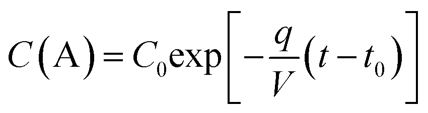
The extended Debye Huckel equation10 was used to determine the activity coefficient (γ) of the analyte of interest, which adjusted for the non-ideality of the electrolyte solution.

 | ||
| Fig. 3 Calibration response of a typical K+ ion selective microgripper showing a Nernstian response and fast response times and hysteresis when the device is exposed to 100 fold concentration gradients (from 0.1 M to 0.001 M KCl. | ||
Characterization
The microgripper sensor devices are designed as single use items that can be used with batch calibration. As the microfabrication method produces identical sensors, calibration and characterization of a limited number of devices from a batch is adequate to understand the response of the whole batch. However, to ensure similar sensor responses fabrication tolerances require the surface area of the electrode and the PEDOT thickness to both be duplicated ±10% and the ISM surface area and morphology to be identical. Steady state cyclic voltammogram were used to determine the electroactive area of the gripper microelectrode, at approximately 1800 ± 20 μm2 as described previously.8 Deposition of PEDOT on the microelectrode resulted in a fibril texture (Fig. 2(b), ESI†). The film thickness was obtained from the total polymerization charge according to established procedures.10 Briefly, the film thickness is correlated to the electrical charge using Faraday's law and assuming 100% current efficiency: t = qM/ρAzF, where t is the film thickness, q is the electrical charge associated with film formation, M is the molar mass of the polymer, F is the Faraday constant, A is the area of the working surface, ρ is the density of the polymer and z is the number of electrons involved. In this study the electropolymerisation process led to reproducible films of approximately 0.2–0.5 μm thickness. In previous publications, Bobacka and coworkers11 obtained films of thickness 0.1–1.5 μm by assuming 2.25 electrons per monomer for a film density 1 g cm−3. Additionally, it is important that identical conditioning and storage procedures are followed to ensure that performance characteristics are kept consistent. It should be noted at this stage that although the Nernstian slope responses and detection limits of individual devices from the same batch will be similar, within random experimental error (standard deviation), the absolute EMF values can vary considerably between different batches. This is a widely accepted phenomenon that relates to differences in the membrane thickness, morphology and composition which can affect ion exchange, leaching, co-extraction and decomposition.12In this work a sub-Nernstian, but reproducible, potentiometric response was observed. For a K+ selective device with a PEDOT layer thickness of approximately 5 μm (which relates to a steady state current of 0.11 ± 0.01 μA in the cyclic voltammogram trace during deposition) that is covered with approximately 20 μm of ISM, the typical microgripper sensor device sensitivity yields a slope response of approximately 52 ± 4 mV per decade, and limit of detection of 2.4 ± 0.1 × 10⁻⁴ M (Fig. 3). This sub-Nernstian response is probably attributable to a combination of factors, including; leaching effects destabilizing the membrane and forming different combinations of analyte and ionophore with different stabilities;13 contamination of the electrode during the fabrication process; and an unknown contribution of the microgripper materials towards the phase boundary potentials of the ISE resulting in a sensor response that includes a time dependency effect dictated by the advanced diffuse layer model.14 The potential drift of the microgripper sensor devices was analyzed to determine the device stability. The microgripper sensor devices have a potential drift of 0.66 mV h−1, which is comparable with previously reported, stable devices and highlights their suitability for application within the field of biological ion analysis.15
The selectivity coefficients, which were determined via the fixed interference method in a background of the cell culture media used (M2 media ionic strength 3.2 × 10⁻² mol dm−3, obtained from Sigma Aldrich UK) against sodium and calcium ions (logKi,j = −1.8 and −3.3 respectively) are also acceptable. These values for selectivity coefficients agree reasonably well other similar values in literature.16 Using the IUPAC definition of response time17 the microgripper sensor device takes 1.4 s to reach 95% of the maximum change of EMF, which relates to the device being capable of monitoring a change of 7.5 mV s−1, well within the temporal resolution of cell signaling. The Na+ ISE gave a poor selectivity coefficient for K+ with a logKi,j = −0.8, giving rise to K+ interference during cellular studies (vide infra).
Actuation interference
Extensive studies were carried out to ascertain and eliminate actuation interference. A full analysis of the studies carried out is beyond the scope of this paper; however, a summary of the results follow.During the sensing of changes in specific ion activities of biological ion from a manipulated cell, it is necessary to simultaneously operate both the microgripper actuators and use the ISE as an electrode in potentiometry. The two electrical circuits are separate; however, under DC control, it was observed that when a current flows through the actuators, an interference signal was formed in the potentiostat response. We believe this occurs because of two factors. The first factor is that, when actuated under DC control, a potential drop relative to ground occurs across the actuators. When the microgripper arms are placed in the highly conductive electrolyte solution the arm becomes a capacitor, with the actuator and solution being the conductive plates and the SU8 being the insulator. The ions within the solution are attracted to the buildup of charge in the actuator, causing a drop in the recorded potential between the ISE and the RE on the potentiostat. At a very low frequency (1 Hz), seen at t = 17 s in Fig. S4(a)†, a fluctuating signal is observed. At this frequency the induced capacitor plate within the electrode is switching between positive and negative, and the ions in solution are responding to that change, causing a cycled positive peak and then a negative drop in the measured ISE potential.
At low frequencies (100 Hz–100 kHz), shown in Fig. S4(b)†, a drop in potential is generally observed. Even though the actuator potential is cycled about zero, only a negative change in measured potential is observed. This is due to two effects: (1) the potentiostat is sampling every 0.1 s so the signal is undergoing an aliasing like effect (where the signal is discretely sampled at a rate that is insufficient to capture the changes in the signal); and (2) the response time of the ISE device and the time for the ions to diffuse are too slow to fully respond to the cycling of the electrons, so a voltage average signal is observed. This means that, in general, the system behaves like that seen in DC actuation. Occasionally, however, positive peaks are seen, though these are more diffuse peaks, which could be due to the fact that as the ion diffusion takes longer, the averaging of the negative ion effects has a greater effect.
No interference peak is seen at higher frequencies (1 MHz), as shown in Fig. S4(b)†, as the frequency is faster than the ions can diffuse and so there is no induced capacitor, meaning that the ions in solution are not affected.
Another possible reason for this observed interference is the connection of the circuits through the grounding loop as the DC or AC current source and the potentiostat are both connected to mains ground. Simply removing one or both of these circuits from the mains circuit removes this link. It was evident that the magnitude of the interference signal is reduced on isolating the circuits, but not entirely removed.
From these studies it was found that the interference signal significantly lowered from 1 MHz to 10 Hz, and the potentiostat was isolated from the mains (Fig. S5(b), ESI†).
Proof of concept results
Cell handling is most commonly performed using denudation vacuum pipettes due to their relatively low cost, ease of handling and versatile nature. The major drawbacks of the pipettes as a manipulation tool are that they are very easy to break and cells, due to their sticky nature, often get stuck and lost inside the capillary. The microgripper has all the advantages of the vacuum pipettes, but with none of the disadvantages as the substantial flex in the microgripper arms makes them more robust.†Initially, a background experiment was run with 60 μm polystyrene beads, in cell culture media to establish that there was no signal response due to any actuation of the microgripper in contact with the polystyrene bead (Fig. 4). The beads themselves are relatively hard and porous compared to an oocyte cell of similar dimensions. The dips at 12.6, 30.6, 41.5 and 52.3 s are probably due to interference, but it should be noted that no positive signal was observed.
 | ||
| Fig. 4 The device response from mechanically stressing a 60 μm inert polystyrene bead. | ||
Proof of concept experiments were performed with mouse oocytes, a female immature ovum. These cells are rich in cytoplasm with an intracellular fluid composition containing approximately 139–141 mM dm−3 K+, our target ion, and 12–14 mM dm−3 Na+, the most likely interfering ion. Additionally, the size of the oocytes (approximately 60 μm) is well within the microgripper tip diameters fabricated. The plasma membrane of the mouse oocyte is surrounded by the zona pellucida composed of three sulphated glycoproteins that serve to bind the spermatozoa. The zona can be removed by placing the cell in acid Tyrode solution.17
A typical microgripper device response is shown in Fig. 5. Fig. 5(a) shows the response of an oocycte cell with its zona intact, and Fig. 5(b) with the zona removed. It is evident that the response of the cell with the zona removed has much less interference compared to the response of the cell with zona removed. There is, additionally, a difference in response when the cell is held well within the scoop (Fig. 5(a) peak 1 and 5(b) peak 3). Within the scoop a well-defined peak is observed for K+ efflux from the cell with no zona (peak 3, Fig. 5(b)). It should be noted here that it was not possible to quantify the magnitude of the applied stress at this stage. However, deformation of the cell as a result of an increase in applied stress was observed. A comparison is made with the response of a Na+ ISE (Fig. 6), which does not show any discernible response for K+.
 | ||
| Fig. 5 K+ ISE response from mechanical stressing of a mouse oocyte (a) with zona, and (b) without zona using the microgripper sensor device actuated at 10 MHz. Peaks 1 and 3 are within the scoop, and peaks 2 and 4 are from the edge of the scoop. | ||
 | ||
| Fig. 6 Na+ ISE responses from mechanical stressing of mouse oocyte using the microgripper sensor device actuated at 10 MHz. | ||
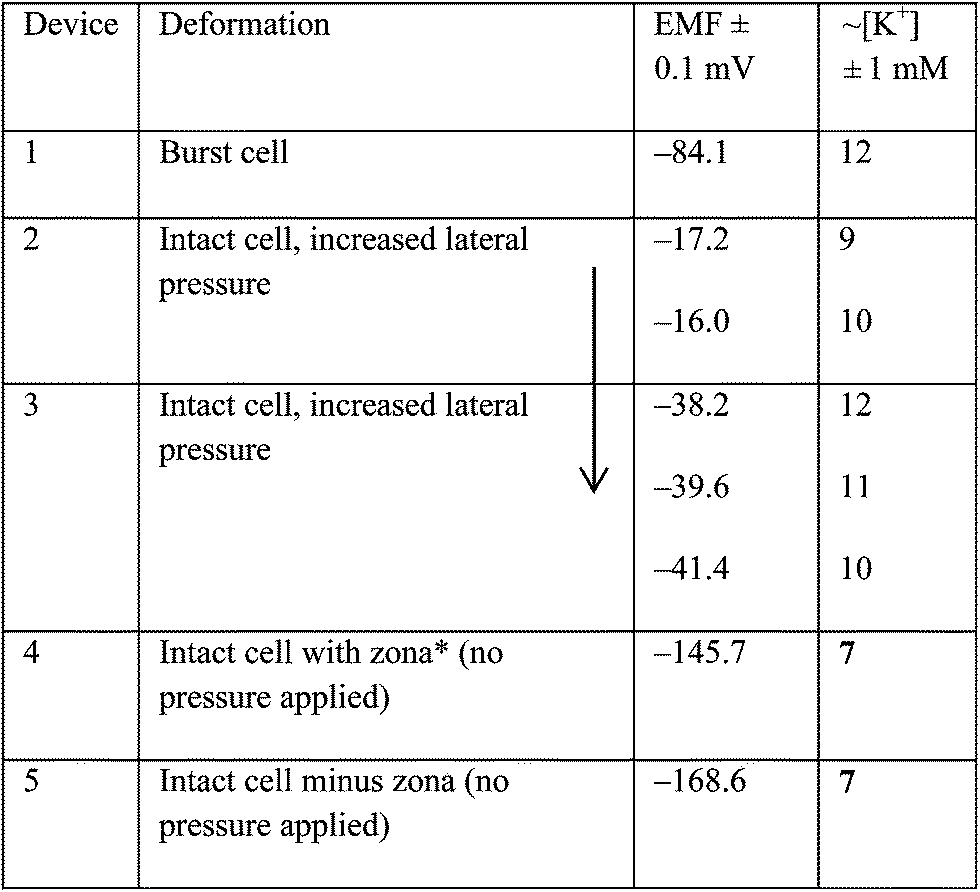
Multiple devices were used to apply variable pressure to the cells (Table 1). In all cases except device 1, care was taken not to completely rupture the cells. EMF measurements were recorded with an increase in force for devices 2 and 3. Devices 2 and 3 show that increasing the stress applied to the cell yields an increase in EMF value, indicating a small increase in the efflux of K+ ion concentration. Device 4 shows the response from an oocyte cell with and without the zona pellucida. It should be noted that the devices presented here are calibrated from a single device from a wafer set and all others are assumed to behave identically. The large variance in the absolute EMF values illustrate that devices from different wafer sets show very variable values, reinforcing that each batch of wafers need to be calibrated before used. However, the repeatable trends in EMF values suggest that an increase in concentration efflux on an increase in applied stress is clearly evident. With more consistent device fabrication any systematic error will be greatly reduced. Cell apoptosis was not observed during the time frame of the measurements unless the cells were ruptured. This paper reports proof of concept studies and is not intended to be a full elucidation of biological processes. However, given that the sensor device mechanically stresses the cell, the signalling response is likely to be dominated by mechanically gated ion channels. There are very few investigations into the role of ion-channel activity in embryonic development but potassium channels are known to exist.18–20 Our results indicated that signal responses from mechanically stressing cells directly correlate to the movement of ions, specifically K+ ions in this case. This observation is justifiable as Trimachi and co-workers made similar observations18 indicating potassium efflux through potassium channels and concurrent cell shrinkage are early indicators of cell death in mouse zygotes caused by cell shrinkage stimulated chemically. Measurements were made non-invasively using self-referencing potassium ion-selective electrodes.
 |
A video demonstrating actuation of a microgripper device whilst moving an oocyte cell is shown in Fig. S5.†
Conclusions
The proofs of concept results using the microgripper sensor device that are presented here indicate that it is a very competitive tool for the manipulation and sensing of single cells. Both the manipulation and sensing technology operate with excellent accuracy and characterization, similar to their competition, but with the added advantage of conducting both actions simultaneously. Exchanging the ionophore to one selective towards a different ion will allow different biological ions to be monitored. This concept is being extended to amperometric devices.Acknowledgements
The CellEctor used in the ion selective electrode fabrication and as the external manipulation system for the microgripper sensor device was kindly lent by Anya Hunt and Norbert Brill from Molecular Machines and Industries (MMI) AG, Zurich, Switzerland. The mouse oocytes used in the proof of concept experiments were supplied by Prof. Mary Herbert and Dr Lisa Lister from the Centre for Life, Newcastle University. We thank EPSRC for part-funding a studentship for RD.Notes and references
- S. S. Rubakhin, E. V. Romanova, P. Nemes and J. V. Sweedler, Nat. Methods, 2011, 8(4), 520–529 Search PubMed.
- S. Hong, Q. Pan and L. P. Lee, Integr. Biol., 2012, 4, 374–380 RSC.
- M. L. Kovarik, D. M. Ornoff, A. T. Melvin, N. C. Dobes, Y. Wang, A. J. Dickinson, P. C. Gach, P. K. Shah and N. L. Allbritton, Anal. Chem., 2013, 85, 451–472 CrossRef CAS PubMed.
- J. Isaksson, P. Kjall, D. Nilsson, N. D. Robinson, M. Berggren and A. Richter-Dahlfors, Nat. Mater., 2007, 6, 673–679 CrossRef CAS PubMed.
- A. J. Bard and L. R. Faulkner, Electrochemical Methods: Fundamentals and Applications, Wiley and Sons, New York, 2000 Search PubMed.
- S. Mkarychev-Mikhailov, A. Shvarev and E. Bakker, Electrochemical Sensors, Biosensors and their Biomedical Applications, Academic Press, USA, 2008 Search PubMed.
- C. Zuliani and D. Diamond, Electrochemica Acta, 2012, 84, 29–34 CrossRef CAS PubMed.
- R. Daunton, A. J. Gallant, D. Wood and R. Kataky, Chem. Commun., 2011, 47, 6446–6448 RSC.
- B. Solano, S. Rolt and D. Wood, Proc. Inst. Mech. Eng., Part C, 2008, 222, 73–86 CrossRef.
- Y. Sulaiman and R. Kataky, J. Electrochem. Soc., 2012, 159(2), F1–F9 CrossRef CAS PubMed.
- J. Bobacka, A. Lewenstam and A. Ivaska, J. Electroanal. Chem., 2000, 489, 17 CrossRef CAS.
- J. N. Butler, Ionic Equilibrium: Solubility and pH Calculations, Wiley and Sons, New York, 1998 Search PubMed.
- E. Lindner and Y. Umezawa, IUPAC, 2008, 80(1), 85–104 CAS.
- M. Miyake, L. D. Chen, G. Pozzi and P. Bulhman, Anal. Chem., 2012, 84, 11014–11111 CrossRef PubMed.
- J. Bobacka, A. Ivaska and A. Lewentam, Chem. Rev., 2008, 108(2), 329–531 CrossRef CAS PubMed.
- J. Bobacka, Anal. Chem., 1999, 71(21), 4932–4937 CrossRef CAS PubMed.
- G. J. Moody, B. B. Saad and J. D. R. Thomas, Analyst, 1989, 114(1), 15–20 RSC.
- J. R. Trimarchi, L. Liu, P. J. S. Smith and D. L. Keefe, Biol. Reprod., 2000, 63, 851–857 CrossRef CAS.
- M. L. Day, S. J. Pickering, M. H. Johnson and D. I. Cook, Nature, 1993, 365, 56–562 CrossRef PubMed.
- C.-G. Hur, E.-J. Kim, S.-K. Cho, Y.-W. Cho, S.-Y. Yoon, H.-M. Tak, C.-W. Kim, C. Choe, J. Han and D. Kang, Reproduction, 2012, 143, 625–636 CrossRef CAS PubMed.
Footnote |
| † Electronic supplementary information (ESI) available: A video showing the microgripper sensor device manipulating a 30 μm polystyrene bead. See DOI: 10.1039/c4ra05052e |
| This journal is © The Royal Society of Chemistry 2014 |