A novel intermediate-temperature all ceramic iron–air redox battery: the effect of current density and cycle duration

Xuan Zhao, Xue Li, Yunhui Gong, Nansheng Xu and Kevin Huang*
Department of Mechanical Engineering, University of South Carolina, Columbia, SC29201, USA. E-mail: kevin.huang@sc.edu

Received 28th March 2014 , Accepted 14th May 2014

First published on 14th May 2014


Abstract

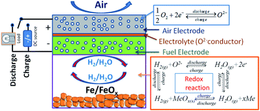
We here report the energy storage characteristics of a new all ceramic iron–air redox battery comprising of a reversible solid oxide fuel cell as the charger/discharger and a Fe–FeOx redox couple as the chemical storage bed. The effects of current density and cycle duration on specific energy and round trip efficiency of the new battery have been systematically studied at 650 °C and 550 °C. The results explicitly show that current density is the most influential variable on the performance, signifying the importance of improving electrochemical performance of the reversible solid oxide fuel cell.


Introduction

Metal–air batteries are a class of promising electrical energy storage systems with high energy density and inexhaustible, storage-free source of cathode oxidant (air). However, commercial development of conventional liquid-electrolyte based metal–air batteries relying on A+ (e.g., A = Li, Na) and/or OH conduction has been severely hampered by the irreversibility, fast capacity decay and electrode deformation, to name just a few reasons. Most of these problems are directly related to the chemical interactions between solid electrodes and liquid electrolytes and blockage of reactants' access to the reactive sites.

To cope with these problems, we have recently demonstrated a new type of metal–air redox battery comprising of all ceramic solid-oxide components: solid oxide metal–air redox batteries (SOMARBs).1–10 The new battery is centered on solid-state oxide-ion transport chemistry, utilizing a reversible solid oxide fuel cell (RSOFC) as the electrical charger/discharger and a metal/metal-oxide mixture as the chemical energy storage bed. Similar works have also been reported by other group.11–19 The working principle of the SOMARB is best illustrated by the chemistry of iron–air shown in Fig. 1; the free-standing Fe–FeOx chemical bed is situated inside the fuel-electrode chamber where an oxygen shuttle H2–H2O is present to transport oxygen between RSOFC and chemical bed. Comparing with the conventional liquid A+ or OH transport based metal–air batteries, the solid-state O2−-transport chemistry enables high rate of charge transfer and ensures minimal chemical reactions between electrolyte and electrodes.


image file: c4ra02768j-f1.tif
Fig. 1 Schematic of the working principle of the all ceramic solid oxide iron–air redox battery.

While the basic energy storage characteristics, e.g. specific energy (SE) and cycleability, of a number of metal–air chemistries have been previously demonstrated in SOMARB for preselected conditions, the effects of operating current density and cycle duration on specific energy and round trip efficiency (RTE) have not been systematically studied even though these two parameters are critically important to the design and operation of a practical SOMARB. This study is aimed to fill this gap by systematically investigating the effects of these two parameters for a solid oxide iron–air redox battery.

Experimental procedures

Battery materials and assembly

The battery for the tests were assembled in a planar button cell configuration as described previously.2 The RSOFC was comprised of a 200 μm thick La0.8Sr0.2Ga0.83Mg0.17O3−δ (LSGM) electrolyte membrane prepared by tape casting and nanostructured Sm0.6Sr0.4CoO3−δ (SSC) cathode and Ni anode prepared by infiltration method.7,8 The active electrode area was 1.3 cm2. The nanostructured Fe–FeOx redox couple material was synthesized from a carbothermic reaction; the details about this synthesis can be found in ref. 8. The iron loading has been consistently kept as 0.7 grams for the tests carried out throughout the study.

Battery testing

At the beginning of each test, the battery cell was first heated up in a mixture of 5% H2 and N2. Once reaching the melting temperature of the sealing glass at 650 °C, the 5% H2–N2 gas was switched to a pure H2 humidified with 3% H2O. After converting iron oxide into iron, the inlet and outlet of H2 flow were closed off, making the fuel-electrode a closed chamber. To create the Fe–FeOx redox couple from pure Fe, a small discharge current of 10 mA cm−2 was applied by the RSOFC to convert H2 into H2O, and further Fe into FeOx. To ensure the attainment of Fe–FeOx equilibrium without over-consuming the active Fe, EMF of the RSOFC was closely monitored during the electrochemical oxidation by intermittently switching between the discharging and OCV states. As soon as the EMF reached the theoretical value, an indication of attainment of Fe–FeOx equilibrium, the electrochemical oxidation was stopped, and the system was ready for the charge–discharge cycles. It is worth mentioning that the equilibrium redox couple is Fe–FeO for 650 °C and Fe–Fe3O4 for 550 °C; the corresponding EMFs of the batteries are 1.03 and 1.07 volt, respectively.

Before each battery's performance evaluation, the battery was first characterized by DC polarization and AC impedance spectroscopy to establish the performance baseline such as VI and PI curves for RSOFC in the temperature range of 550–650 °C. The typical impedance spectrum was collected in the frequency range of 0.01–6.3 × 10⁵ Hz and an AC perturbation amplitude of 10 mV. As a standard practice in electrochemical impedance spectroscopy, the area-specific ohmic and polarization resistances were extracted from the spectrum at high and low frequency region, respectively. These initial performances were used to compare with those post-cycled batteries to discern performance degradation.

To examine the effects of current density and cycle duration on battery's SE and round-trip efficiency (RTE), a testing matrix shown in Table 1 was created. The execution of this testing matrix was carried out on a single-cycle basis to minimize uncontrollable variables such as “aging”. After each cycle H2–3% H2O was re-introduced into the fuel electrode chamber before the next test. A Solartron 1260/1287 Electrochemical System was employed to characterize the electrical performance of the battery under various operating conditions with software modules such as impedance, OCV–t and galvanic cycles.

Table 1 Current density and cycle duration used in the studya
T °C Constants Independent variables (t in min; j in mA cm−2)
a j – current density; t – cycle duration for single discharge or charge cycle.
650 j = 25 t = 10 t = 20 t = 30 t = 40
t = 10 j = 25 j = 50 j = 75 j = 100
550 j = 10 t = 10 t = 20 t = 30 t = 40
t = 10 j = 10 j = 20 j = 30 j = 40


Results and discussion

Fuel cell performance of the battery

The fuel cell performance of the RSOFC used by the battery is represented in Fig. 2 by AC impedance spectrum and VI (or PI) characteristic measured at 550 and 650 °C with air and H2–3% H2O as the oxidant and fuel, respectively. The total cell resistance increases from 3.92 Ω cm2 at 650 °C to 10.55 Ω cm2 at 550 °C. The corresponding peak power density decreases from 176 mW cm−2 @ 280 mA cm−2 at 650 °C to 64 mW cm−2 @ 102 mA cm−2 at 550 °C. These performances are typical of a thick-film LSGM based SOFC for the temperatures range. The operating current densities selected for the study are within 10% of the peak current densities to ensure meaningful cell voltage for practical operation.
image file: c4ra02768j-f2.tif
Fig. 2 Fuel cell performance of RSOFC tested in H2–3% H2O gas mixture; (a) impedance spectra and (b) VI & PI characteristics measured under different temperatures.

Battery characteristics

The battery voltage as a function of operating current density and cycle duration is shown in Fig. 3 for 550 and 650 °C. For either temperature, it is evident that the operating current density (j) has a greater effect than cycle duration (t). This is understandable according to the following simplified voltage equation for an electrochemical device:
 
E = EN ± iR (1)
where E is the battery's terminal voltage; EN is the Nernst potential; i is the applied current and R is the total resistance of the battery. Evidently, higher j leads to higher voltage loss iR, resulting in lower E for the discharge and higher E for the charge. There would be no effect from t as long as the “aging” effect is negligible in the battery, which is particularly true for single-cycle study carried out herein.

image file: c4ra02768j-f3.tif
Fig. 3 Etj characteristics of the battery measured at 650 °C (a) and 550 °C (b).

Calculated from Fig. 3, the effects of j and t on discharge specific energy (DSE)/charge specific energy (CSE) and RTE are shown in Fig. 4(a)–(c) for 650 °C and (d)–(f) for 550 °C, respectively. Each calculation was normalized to the actual Fe consumed by the oxygen flux provided by the RSOFC. At a fixed j (Fig. 4(a) and (d)), both of the DSE and the CSE were stable over different cycle durations (t). In contrast, at a fixed t (Fig. 4(b) and (e)), DSE and CSE decrease as current density j increases. The RTE is calculated by:

 
RTE = DSE/CSE (2)


image file: c4ra02768j-f4.tif
Fig. 4 (a) DSE/CSE–t relationship with fixed j; (b) DSE/CSE–j relationship with fixed t; (c) RTE–tj relationship of the battery measured at 650 °C; similar relationships measured at 550 °C are shown in (d)–(f), respectively.

It is evident from Fig. 4(c) and (f) that j also has a greater impact on RTE than t, which is as expected.

The insensitivity of RTE to t at a fixed j = 25 mA cm−2 for 650 °C and j = 10 mA cm−2 for 550 °C suggests good redox reversibility of the Fe–FeO and Fe–F3O4 redox couples, respectively, under these circumstances. The good reversibility observed is believed to largely benefit from the carbothermic reaction based synthesis yielding robust redox materials. These multi-variable comparisons further infer that operating a SOMARB under a relatively lower j for longer cycle duration to achieve a required energy storage capacity is a preferred approach to maintaining a high RTE; this is also a strategy commonly used for lithium-ion batteries (LIBs). However, the rate capacity presented by SOMARB here is still close to one order of magnitude higher than LIBs. As the performance of RSOFC at reduced temperatures is being further improved by the use of thin-film electrolyte and nanostructured electrodes, the rate capacity as well as energy capacity of SOMARB can be further enhanced. Operation under 100 mA cm−2 at a reduced temperature, for example, is routinely achievable by an RSOFC.

Conclusions

A new class of all-ceramic solid-oxide iron–air redox batteries comprising of a reversible solid oxide fuel cell and multivalent metal/metal-oxide chemical bed has been recently demonstrated with great potential to overcome the challenges facing conventional liquid-based iron–air batteries. This study presented a systematic study of the new battery on the effects of operating current density and cycle duration on the specific energy and round trip efficiency at 650 °C and 550 °C, under which two respective equilibrium redox couples of Fe–FeO and Fe–Fe3O4 predominate. The results explicitly showed that the current density is the most pronounced factor affecting the battery's performance, signifying the importance of retaining electrochemical performance of RSOFC for the new battery.

References

  1. N. Xu, X. Li, X. Zhao, J. B. Goodenough and K. Huang, Energy Environ. Sci., 2011, 4, 4942–4946 CAS.
  2. X. Zhao, N. Xu, X. Li, Y. Gong and K. Huang, RSC Adv., 2012, 2, 10163–10166 RSC.
  3. X. Zhao, Y. Gong, X. Li, N. Xu and K. Huang, J. Electrochem. Soc., 2013, 160, A1241–A1247 CrossRef CAS PubMed.
  4. X. Zhao, X. Li, Y. Gong, N. Xu, K. Romito and K. Huang, Chem. Commun., 2013, 49, 5357–5359 RSC.
  5. X. Zhao, Y. Gong, X. Li, N. Xu and K. Huang, J. Electrochem. Soc., 2013, 160, A1716–A1719 CrossRef CAS PubMed.
  6. M. Guo, X. Zhao, R. E. White and K. Huang, J. Electrochem. Soc., 2013, 160, A2085–A2092 CrossRef CAS PubMed.
  7. X. Zhao, Y. Gong, X. Li, N. Xu and K. Huang, J. Mater. Chem. A, 2013, 1, 14858–14861 CAS.
  8. X. Zhao, X. Li, Y. Gong and K. Huang, Chem. Commun., 2014, 50, 623–625 RSC.
  9. X. Zhao, N. Xu, X. Li, Y. Gong and K. Huang, ECS Trans., 2013, 50, 115–123 CrossRef PubMed.
  10. X. Zhao, N. Xu, X. Li, Y. Gong and K. Huang, ECS Trans., 2013, 45, 113–121 CrossRef CAS PubMed.
  11. H. Landes and R. Reichenbacher, ECS Trans., 2013, 50, 47–68 CrossRef PubMed.
  12. A. Inoishi, Y. W. Ju, S. Ida and T. Ishihara, J. Power Sources, 2013, 229, 12–15 CrossRef CAS PubMed.
  13. A. Inoishi, S. Ida, S. Uratani, T. Okano and T. Ishihara, Phys. Chem. Chem. Phys., 2012, 14, 12818–12822 RSC.
  14. A. Inoishi, Y. W. Ju, S. Ida and T. Ishihara, Chem. Commun., 2013, 49, 4691–4693 RSC.
  15. A. Inoishi, S. Ida, S. Uratani, T. Okano and T. Ishihara, RSC Adv., 2013, 3, 3024–3030 RSC.
  16. W. Drenckhahn, H. Greiner, M. Kuhne, H. Landes, A. Leonide, K. Litzinger, C. Lu, C. Schuh, J. Shull and T. Soller, ECS Trans., 2013, 50, 125–135 CrossRef PubMed.
  17. H. Ohmori, S. Uratani and H. Iwai, J. Power Sources, 2012, 208, 383–390 CrossRef CAS PubMed.
  18. A. Inoishi, Y. Okamoto, Y. W. Ju, S. Ida and T. Ishihara, RSC Adv., 2013, 3, 8820–8825 RSC.
  19. A. Inoishi, T. Ishihara, S. Ida, Y. W. Ju and T. Sakai, J. Mater. Chem. A, 2013, 1, 15212–15215 CAS.

This journal is © The Royal Society of Chemistry 2014
Click here to see how this site uses Cookies. View our privacy policy here.