DOI:
10.1039/C4RA01376J
(Paper)
RSC Adv., 2014,
4, 21221-21229
Facile synthesis of WO3 with reduced particle size on zeolite and enhanced photocatalytic activity†
Received
17th February 2014
, Accepted 11th April 2014
First published on 15th April 2014
Abstract
WO3 supported on zeolite-Y (WO3-ZY) was successfully synthesized by a facile impregnation method and well characterized by various techniques. The photocatalytic activity of the prepared catalysts was investigated for the degradation of Rhodamine B (RhB) under visible, UV and solar light irradiation. The enhanced photocatalytic activity was observed for the catalyst WO3-ZY, which may be due to the presence of more active sites that can adsorb a greater number of dye molecules. The TEM, FESEM and adsorption studies confirm that the WO3 supported on zeolite-Y has a very small particle size of about 8 nm compared with the bare WO3 at 97 nm. The efficient electron–hole pair separation and the role of active species were investigated by photoluminescence spectroscopy and the test of the effect of scavengers, respectively. The mechanism for the photocatalytic degradation of RhB was proposed and the pathway of RhB degradation was illustrated schematically.
Introduction
Semiconductor photocatalysis is a promising technique for addressing environmental issues such as energy storage and decontamination of environmental pollution.1 This technique provides clean and recyclable hydrogen energy and also can utilize solar energy to decompose organic and inorganic pollutants present in air and aqueous media.2,3 TiO2 is the most widely used and best photocatalytic material; however, only a small fraction of solar light (3–5%) can be utilized due to its wide band gap.4,5 Even though the visible light photocatalytic activity of TiO2 has been reported in nitrogen-doped TiO2, the quantum efficiency of the nitrogen-doped TiO2 is much lower than that under UV light irradiation.6 In contrast, WO3 is n-type semiconductor that has strong absorption in the solar spectrum, stable physicochemical properties, and is resistant to photocorrosion effects.7 The narrow band gap of about 2.4–2.8 eV and deeper valance band (+3.1 eV) results in additional advantages for visible light driven photocatalysis.7 However, due to fast recombination of electron–hole pairs and low conduction band level, pure WO3 is not an efficient photocatalyst.8 However, it has been found that the photocatalytic efficiency of the pure WO3 can be enhanced by several methods. Some examples are tuning a physical property such as morphology and particle size,9–12 semiconductor coupling,13–16 noble metal deposition,7,14,15,17 and metal ion doping.18 Increasing the surface area and suppressing the electron–hole pair recombination can also enhance the photocatalytic activity of WO3,8 but there are few reports available on tuning the physical properties of WO3 to improve the efficiency under visible light irradiation.19
Recently, researchers have intensively focused on mesoporous materials such as zeolite as a support for metal oxides that influence photocatalytic activity through structural modification.20–23 The zeolitic materials have gained significant importance due to their high surface area, thermal stability and their specific photophysical properties in charge and electron transfer processes.24,25 The use of zeolite as a support for metal oxides improves the amount of photons absorbed by the catalyst and reduces the amount of metal oxides required.26 Despite that there are several metal oxides supported on zeolitic materials that proved to be better photocatalysts, there is no report on WO3 supported on zeolitic materials for photocatalytic applications.
For the first time, we report a facile synthesis of WO3 supported on zeolite-Y catalyst by impregnation method and its photocatalytic efficiency for the degradation of Rhodamine B (RhB) under visible, UV and solar light irradiation. The prepared catalysts were well characterized by powder X-ray diffraction (PXRD), X-ray photoelectron spectroscopy (XPS), transmission electron microscopy (TEM), field emission scanning electron microscope (FESEM), Raman, Fourier transform infrared spectroscopy (FT-IR) and UV-vis diffuse reflectance spectra (UV-DRS) techniques. Greatly enhanced photocatalytic activity was observed in the catalyst WO3 loaded on zeolite-Y. The TEM, FESEM and adsorption studies confirmed the reduced particle size of the catalyst. The efficient electron–hole pair separation of the catalysts was investigated by photoluminescence (PL) spectroscopic techniques. The photocatalytic activity in the presence of different scavengers was demonstrated by testing which of the active species plays an important role in the degradation of the RhB. The mechanism for the photocatalytic degradation of RhB is proposed; the pathway of RhB degradation is also illustrated schematically.
Experimental
Materials
All analytical grade reagents of Na2WO4·2H2O, H2WO4, RhB, BaSO4 and zeolite-Y were used as such without further purification. Deionized and double distilled water was used throughout this work.
Synthesis
The WO3-supported zeolite-Y (WO3-ZY) catalyst was prepared by the facile impregnation method as follows. The zeolite-Y (1 g) was put into an aqueous medium and stirred. After that, 5 g of H2WO4 was added into the above reaction mixture. Then, the reaction mixture was refluxed at 100 °C for 24 h. The obtained precipitate was collected by centrifugation, washed several times using distilled water and dried. The dried sample was calcinated at 500 °C for 3 h. For comparison, pure WO3 was prepared by the precipitation method as reported in the literature.27 The sodium tungstate was dissolved in distilled water and slowly heated to 85 °C. The appropriate amount of warm, concentrated nitric acid was added drop-wise to this solution with vigorous stirring. The mixed solution was held at the same temperature for 30 min under continuous stirring. The precipitate was allowed to settle overnight at room temperature, then washed by adding a large amount of water and allowing the precipitates to settle before decanting the liquid. Finally, the precipitate was separated by centrifugation and dried. After drying, the pure WO3 was calcined at 500 °C for 3 h.
Characterization
PXRD data were collected by a PAN analytical X'pert Pro dual goniometer diffractometer. The data were collected with a step size of 0.008° and a scan rate of 0.5° min−1. The radiation used was Cu-Kα (1.5418 Å) with a Ni filter, and the data collection was carried out using a flat holder in Bragg–Brentango geometry. XPS analysis was carried out by Kratos Axis-Ultra DLD instrument by passing 200 eV energy. During XPS analysis the sample was irradiated with Mg Kα and the data collected at sweep rates of 2 eV and 5 eV in a wide and narrow range scan, respectively. TEM analysis was done by JEOL model 2010 FasTEM instrument with a 200 kV accelerating voltage. An FESEM image was obtained by a Carl Zeiss SIGMA instrument with 1.2 nm resolution. The energy-dispersive X-ray spectra (EDX) were recorded using the INCAx-act Oxford Instrument equipped with SEM. Raman spectra were recorded by employing a Horiba JY LabRAMHR 800 Raman spectrometer coupled with a microscope in reflectance mode with a 514 nm excitation laser source. UV-DRS spectra were recorded on Shimadzu UV-2450 UV-visible spectrophotometer equipped with an integrated sphere assembly using BaSO4 as the reflectance sample. FT-IR analysis was performed using Jasco FTIR 460 plus spectrophotometer. The PL spectrum was recorded by a JASCO FP-6500 spectrofluorometer with 300 nm excitation wavelength.
Photocatalytic test
The photocatalytic degradation of a model pollutant RhB was chosen to investigate the photocatalytic activity of the prepared catalysts. In a typical experiment, 25 mg of the catalyst was suspended in 50 mL of aqueous solution contains 10 mg L−1 of RhB dye. Prior to irradiation, the suspension was held for 30 min in the dark to achieve adsorption–desorption equilibrium by aeration. Photocatalytic activity was investigated under visible and UV light irradiation by 300 W tungsten halogen lamp (8500 lumen) and 125 W medium pressure mercury lamp emitting 365 nm (110 μW cm−2, measured by a Lutron UV light Meter) light respectively. The reaction mixture was aerated continuously under irradiation until the reaction mixture was thorough mix. At the given time interval 3.5 mL of the sample was withdrawn and centrifuged to separate the catalyst. The degradation of RhB was determined by measuring the maximum absorbance at 554 nm on a UV-vis spectrophotometer.
Results and discussion
Characterization
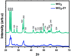
Crystalline structure. The PXRD pattern of the prepared catalysts is shown in Fig. 1. The peaks obtained in the pattern are indexed with standard data (JCPDS no. 83-0950) and correspond to the monoclinic phase structure. In pure WO3, the pattern shows very sharp peaks that represent the high crystallinity and greater particle size. The diffraction peaks appeared in the WO3-ZY corresponds to WO3 indicating the formation of WO3 on the zeolite-Y (please see the ESI† for the PXRD pattern of pure zeolite-Y). On the other hand, there are no sharp peaks in the diffraction pattern of WO3-ZY that could be attributed to the smaller size particles of WO3. The crystalline size of the WO3 and WO3-ZY in the (002) plane is calculated by the Scherer formula to be around 43 and 26 nm, respectively. This result shows that the growth of WO3 on zeolite-Y is very limited and controlled.
 |
| Fig. 1 PXRD pattern of the WO3 and WO3-ZY. | |
Morphology and particle size. The FESEM image of the WO3 sample shows spherical shaped particles with the average size of 102 nm, as shown in Fig. 2(a). The FESEM image of WO3-ZY shows very small particles (12 nm) as shown in Fig. 2(c). Since there are no distinct particles, it is difficult to obtain particle size from the image. For comparison, the FESEM image of zeolite-Y is shown in Fig. 2(b). The TEM image of WO3 is given in Fig. 2(d), which further confirms the shape of the particles. The average particle size was calculated from the TEM image to be around 97 nm, which is close to that calculated from FESEM image. The highly magnified TEM image of WO3 is shown in Fig. 2(e). The inter-planar distance from the TEM image was calculated to be 0.39 nm, which is well matched with the lattice spacing of (200) planes of the monoclinic WO3 structure. The TEM image of WO3-ZY shows that the particles are very small in size, as shown in Fig. 2(f); the particle size distribution is shown in the inset. The calculated average particle size of WO3-ZY from Fig. 2(f) is around 8 nm. These FESEM and TEM results shows that the WO3 particle size was reduced from 97 nm to 8 nm under the given reaction conditions. This decrease in particle size may provide more active sites. The elements present in the catalysts WO3 and WO3-ZY were confirmed by the EDX analysis and are shown in Fig. 3(a and b).
 |
| Fig. 2 FESEM images of (a) WO3, (b) zeolite-Y, (c) WO3-ZY, (d and e); TEM and HR TEM images of WO3; and (f) TEM image of WO3-ZY. | |
 |
| Fig. 3 EDX spectra of (a) WO3; and (b) WO3-ZY. | |
XPS analysis. The elements and chemical states present in the catalysts were further investigated by XPS analysis. The overview XPS spectra of the samples WO3 and WO3-ZY are shown in Fig. 4(a). The spectra clearly show the presence of W4d, W4f and O1s peaks and the respective oxidation states of the elements are indexed. The narrow range spectra of W4d and O1s corresponding to WO3 and WO3-ZY are shown in Fig. 4(b and c). The binding energy observed at around 247 and 530 eV in Fig. 4(b and c) is ascribed to W4d and O1s of WO3, respectively. An obvious shift of W4d and O1s peaks in WO3-ZY to a higher binding energy is observed in the spectra, which is attributed to the strong interaction between WO3 and zeolite-Y. The O1s peak shift from 530 eV to 538 eV is attributed to the oxygen of WO3 hydrogen bonded to the zeolite surface.28 On the other hand, the particle size variation and lattice variation can also change the binding energy in XPS. The particle size reduction will result in a higher binding energy shift, which clearly shows the reduction of WO3 particle size in WO3-ZY.29 This reduction in particle size is in good agreement with results obtained from FESEM and TEM analysis.
 |
| Fig. 4 (a) XPS survey spectra of WO3 and WO3-ZY, and narrow range survey spectra of (b) W4d, (c) O1s of WO3 and WO3-ZY. | |
Raman spectral analysis. The Raman spectra of the prepared catalysts consist of three main regions, less than 200, 200–400 and 600–900 cm−1, as shown in Fig. 5(a), which was well matched with the literature report of the monoclinic tungsten oxide phase.30,31 The Raman peaks at 135 and 184 cm−1 correspond to the (W2O2)n chains.30 The W–O–W bending modes of bridging oxide ion peaks appear at 273 and 329 cm−1.30 The peaks at 720 and 809 cm−1 are attributable to the W–O–W stretching mode in the tungsten oxide network.32 The intensity of the Raman peaks was very low for the catalyst WO3-ZY, which may be due to the very small particle size.
 |
| Fig. 5 (a) Raman and (b) FT-IR spectra of WO3 and WO3-ZY. | |
FT-IR analysis. The FT-IR spectral characterization was carried out to analyze the catalysts; the obtained spectra are shown in Fig. 5(b). The strong absorption peaks for pure WO3 were observed in the 500–900 cm−1 range, which corresponds to the ν(O–W–O) stretching mode.33 The peak at around 750 cm−1 is attributable to the ν(O–W–O) stretching mode.34 The bands in the range of 3200–3550 cm−1 are ascribed to the ν(O–H) stretching, and the band at 1625 cm−1 corresponds to the δ(O–H) bending modes of the coordinated water.33
Optical properties. The optical properties of the catalysts were investigated by UV-vis DRS spectroscopy; results are shown in Fig. 6(a). The spectra reveal that all catalysts have absorption edges above a wavelength of 400 nm. The band gap energies of the samples can be calculated by the following equation35,36where α, ν, Eg and A are the absorption coefficient, frequency of the light, band gap energy and a constant, respectively; and n is the type of optical transition of a semiconductor, which is 1. The band gap energy (Eg) of the catalysts can be calculated from the intercept of the tangent to the X axis from a plot of (αhν)1/2 versus energy (hν), as given in Fig. 6(b). The calculated band gap energies of the samples are 2.52 and 2.73 eV for WO3 and WO3-ZY, respectively. The valance band (VB) edge potential of a semiconductor at the point of zero charge can be calculated from the following equation37where EVB is the VB edge potential; X is the electronegativity of the semiconductor; Ec is the energy of free electrons on the hydrogen scale (about 4.5 eV); and Eg is the band gap energy of the semiconductor. The conduction band (CB) edge potential (ECB) can be determined by ECB = EVB − Eg. The X value for WO3 is about 6.60, and the calculated EVB and ECB of the catalysts are 3.36 and 0.84 eV, respectively, for WO3 and 3.46 and 0.73 eV, respectively, for WO3-ZY. The band gap energy changes and blue shift in the UV-vis spectrum clearly suggest that the particle size of the catalyst has decreased.
 |
| Fig. 6 (a) UV-vis DRS and (b) plot of (αhν)1/2 vs. hν of WO3 and WO3-ZY. | |
Photocatalytic activity. The photocatalytic activity of the prepared catalysts for the degradation of RhB was demonstrated under visible, UV and solar light irradiation. Before that, the blank experiment without any catalyst was carried out to test the stability of RhB under visible, UV and solar light irradiation. The UV-vis spectral changes of RhB under various light irradiations were recorded (see Fig. S1–S3 in the ESI†). There were no significant changes observed in the UV-vis spectrum, which confirms the degradation of RhB is almost zero or negligible under the various light irradiations in the absence of any catalyst. These experimental results show RhB in aqueous medium is highly stable under the given light irradiation. The percent degradation of RhB was calculated by the following equation |
%D = (A0 − At)/A0 × 100
| (3) |
where %D is the percentage of degradation, and A0 and At are initial absorption and absorption at time t, respectively.Photocatalytic degradation of organic compounds usually follows the pseudo-first order kinetics model. The rate constant for the degradation of RhB is calculated using the following Langmuir–Hishelwood kinetic equation38,39
where
C0 is the initial concentration of the dye solution (mol L
−1);
C is the concentration of the dye solution at time
t (mol L
−1); and
kapp is the apparent rate constant (min
−1).
The rate constant for the degradation of RhB was calculated from the slope of the plot, ln(C0/C), vs. irradiation time.
Under visible light. The photocatalytic activity for the degradation of RhB by the catalysts under visible light irradiation is shown in Fig. 7(a). The enhanced photocatalytic activity was observed by the catalyst WO3-ZY, which may be due to high percentage adsorption of dye on the surface of the catalyst. The percentage adsorption of RhB on the surface of the catalyst under dark after 30 min is shown in the inset figure of Fig. 7(a). The high percentage adsorption of about 30% was achieved by the catalyst WO3-ZY, whereas WO3 shows less than 10% adsorption. This high percentage of adsorption may be due to decreasing the particle size of WO3 on zeolite-Y, which may provide more active sites to adsorb dye molecules. This study experimentally confirms the reduced particle size of the catalyst WO3-ZY. The photocatalytic activity of zeolite-Y catalyst for the degradation of RhB is very minimum in visible light when compared with WO3-ZY, as shown in Fig. 7(a).
 |
| Fig. 7 Percent degradation of RhB under visible light irradiation (a) over different catalysts, over WO3-ZY (b) on varying the amount of catalyst, (c) on varying the amount of RhB and (d) under different light irradiation. | |
Optimization study. To effectively utilize the catalyst in a low amount and get high efficiency at an optimum dye concentration, two sets of experiments were done. First, we changed the amount of WO3-ZY from 0.25 g L−1 to 1 g L−1 while keeping the 10 mg L−1 dye concentration constant. Second, we changed the dye concentration from 5 mg L−1 to 20 mg L−1 while keeping 0.5 g L−1 catalyst constant. The increased percentage degradation of 58% to 92% was observed when the amount of the catalyst was increased from 0.25 g L−1 to 0.5 g L−1, respectively. This may be due to the increased availability of active sites on the catalyst surface, thereby increasing the available amount of catalyst. Upon further increasing the amount of catalyst, the degradation efficiency does not increase, as shown in Fig. 7(b). This may be due to the aggregation of a large amount of catalyst, which causes a reduction in the number of active sites for the adsorption of dye molecules and photons. Moreover, a high concentration of catalyst creates turbidity and thus reduces the penetration intensity of light radiation by the scattering effect.40,41 As the dye concentration increases, the photocatalytic activity decreases, as shown in Fig. 7(c). This may be due to a decreased number of photons reaching the surface of the catalyst because more photons are absorbed by dye molecules.42 These experimental results suggest that the optimum reaction condition to achieve better efficiency is 0.5 g L−1 catalyst and 10 mg L−1 dye concentration.
Under UV and solar light. The photocatalytic efficiency of the catalyst WO3-ZY was investigated under UV and solar light irradiation. The photocatalytic degradation of about 86% was observed at 140 min under UV light irradiation, which is a very high efficiency when compared with WO3 (see Fig. S4 in the ESI† for the degradation profile of different catalysts); this result is consistent with that obtained under visible light irradiation. Under solar light irradiation, 95% degradation was observed at 180 min. The rate constants for the degradation of RhB under different light irradiations are given in Fig. 7(d). The rate constant increased in the order visible < UV < solar light irradiation. The high rate constant under solar irradiation suggested that the catalyst can be efficiently used for the conversion of solar energy.
Reaction mechanism and degradation pathway
Recombination of electron–hole pair. The photocatalytic efficiency of a catalyst can be enhanced by inhibiting the recombination of photo-generated electron–hole pairs. The lower PL intensity of the catalyst can have a lower recombination rate and a higher photocatalytic activity as the recombination of electron–hole pair releases energy in the form of fluorescence.43,44 The PL spectra of the catalysts are shown in Fig. 8(a). The PL intensity of the catalyst WO3-ZY shows the lowest intensity compared with pure WO3. It is suggested that WO3-ZY has the lowest electron–hole pair recombination rate, which is consistent with the high photocatalytic activity observed. This decrease in the PL intensity may be due to the small particle size of the catalyst, which can increase the surface area and thereby increase the interfacial charge–carrier transfer.19
 |
| Fig. 8 (a) PL spectrum of the catalysts and (b) effect of electron acceptor for the degradation of RhB. | |
Role of electron acceptors. Electron acceptors such as air and hydrogen peroxide can create more active radicals of ˙O2− and ˙OH, respectively, which are strong enough to degrade organic molecules. The experimental results for the photocatalytic degradation of RhB over WO3-ZY in the presence of air, hydrogen peroxide (5 mmol) and no acceptor under visible light irradiation are shown in Fig. 8(b). The kapp of 0.0052 min−1 in the absence of an electron acceptor increased to 0.0143 min−1 after the addition of hydrogen peroxide. This enhanced photocatalytic activity in the presence of electron acceptors may be due to a decreased recombination rate of electron–hole pairs and formation of more active radicals.
Role of active species. The holes (h+) and radical trapping experiments were carried out to investigate the role of reactive species in the photocatalytic degradation of RhB over WO3-ZY under visible light irradiation. The changes of kapp for the degradation of RhB in the presence of different scavengers (5 mmol) are shown in Fig. 9(a). When t-BuOH (as the ˙OH scavenger) was added,45 the kapp decreased slightly to 0.0035 min−1 from 0.0052 min−1. On the other hand, the kapp of RhB degradation decreased to 0.0023 min−1 when benzoquinone (BQ) was added as the ˙O2− scavenger.46,47 However, upon the addition of ammonium oxalate (AO) as the h+ scavenger,48 the kapp decreased radically, to 0.0005 min−1. These decreases in the kapp upon the addition of different scavengers suggested that h+ and ˙O2− play a major role, whereas ˙OH is a minor active species for the degradation of RhB. The active radical ˙O2− can be formed by reacting photo-generated electrons with O2 molecules adsorbed on the surface of the catalyst,1 which indicates that O2 is an efficient electron acceptor for generating ˙O2− and inhibiting electron–hole pair recombination.49,50
 |
| Fig. 9 (a) Effect of different scavengers; (b) possible mechanism; and (c) the temporal UV-vis absorption spectral variation for the photocatalytic degradation of RhB over WO3-ZY. | |
Possible reaction mechanism and degradation pathway
Based on the effect of scavengers, a possible mechanism for the photocatalytic degradation of RhB over WO3-ZY is illustrated in Fig. 9(b). As shown in Fig. 9(b), the electron–hole pair is created by the illumination of the catalyst. Then the photoinduced electrons in the CB react with an O2 molecule adsorbed on the surface of the catalyst and form ˙O2− radicals to degrade RhB. Meanwhile, the photoinduced holes in the VB can directly degrade RhB. The photocatalytic degradation of RhB can be illustrated as follows: |
WO3 + hν → e−CB + h+VB
| (5) |
|
e−CB + O2 → ˙O2− + catalyst
| (6) |
|
RhB + ˙O2− → products
| (7) |
|
RhB + h+VB → products
| (8) |
It is well known that the degradation of RhB proceeds via two processes of N-de-ethylation and destruction of the conjugated structure.51 The temporal UV-vis absorption spectral variation for the photocatalytic degradation of RhB under solar light irradiation is shown in Fig. 9(c). The absorption band at 554 nm has decreased, which suggests the degradation of the xanthene ring in RhB. The blue shift in the absorption spectrum is ascribed to the formation of de-ethylated RhB.52 Based on the results obtained from the UV-vis spectral changes, we propose the degradation pathway of RhB schematically in Scheme 1: the degradation of RhB occurred through de-ethlyation process, followed by the destruction of the conjugated xanthane structure in RhB, which produces the benzenoid intermediates.53 After that occurs, the schematic diagram shows the ring opening of the intermediates and mineralization process.
 |
| Scheme 1 Proposed degradation pathway for the photocatalytic degradation of RhB. | |
Conclusion
In this study, we have successfully synthesized and thoroughly characterized both pure WO3 and WO3 supported on zeolite-Y. The TEM, FESEM and adsorption studies confirm that the catalyst WO3-ZY has a very small particle size: 8 nm. The photocatalytic activity of the prepared catalysts was investigated for the degradation of RhB under visible, UV and solar light irradiation. The enhanced photocatalytic activity was observed for the catalyst WO3-ZY. The higher photocatalytic activity of WO3-ZY under solar light irradiation compared with other light irradiation sources suggests the catalyst can be utilized for solar energy conversion. The efficient electron–hole pair separation of the catalyst provides the condition whereby enhanced photocatalytic activity is obtained, as confirmed by PL spectra. The test of the effect of scavengers shows that the active species h+ and ˙O2− play a major role in the photocatalytic degradation of RhB. The proposed mechanism for the photocatalysis and degradation pathway of RhB is illustrated: it involves N-de-ethylation, destruction of conjugated structure, ring opening and mineralization processes.
Acknowledgements
The authors thank DST-SERC for financial support, sanction no. SR\FT\CS-042\2008.
Notes and references
- M. R. Hoffmann, S. T. Martin, W. Choi and D. W. Bahnemann, Chem. Rev., 1995, 95, 69 CrossRef CAS.
- S. C. Zhang, J. D. Shen, H. B. Fu, W. Y. Dong, Z. J. Zheng and L. Y. Shi, J. Solid State Chem., 2007, 180, 1456 CrossRef CAS PubMed.
- A. Fujishima and K. Honda, Nature, 1972, 238, 37 CrossRef CAS.
- W. K. Ho, J. C. Yu and S. C. Lee, Chem. Commun., 2006, 1115 RSC.
- Y. Cong, J. L. Zhang, F. Chen and M. Anpo, J. Phys. Chem. C, 2007, 111, 6976 CAS.
- H. Irie, Y. Watanabe and K. Hashimoto, J. Phys. Chem. B, 2003, 107, 5483 CrossRef CAS.
- G. R. Bamwenda and H. Arakawa, Appl. Catal., A, 2001, 210, 181 CrossRef CAS.
- Z. G. Zhao and M. Miyauchi, Angew. Chem., Int. Ed., 2008, 47, 7051 CrossRef CAS PubMed.
- D. Chen and J. H. Ye, Adv. Funct. Mater., 2008, 18, 1922 CrossRef CAS.
- Y. F. Guo, X. Quan, N. Lu, H. M. Zhao and S. Chen, Environ. Sci. Technol., 2007, 41, 4422 CrossRef CAS.
- Z. G. Zhao and M. Miyauchi, J. Phys. Chem. C, 2009, 113, 6539 CAS.
- K. Z. Lv, J. Li, X. X. Qing, W. Z. Li and Q. Y. Chen, J. Hazard. Mater., 2011, 189, 329 CrossRef CAS PubMed.
- J. Papp, S. Soled, K. Dwight and A. Wold, Chem. Mater., 1994, 6, 496 CrossRef CAS.
- H. W. Choi, E. J. Kim and S. H. Hahn, Chem.–Eng. J., 2010, 161, 285 CrossRef CAS PubMed.
- S. M. Sun, W. Z. Wang, S. Z. Zeng, M. Shang and L. Zhang, J. Hazard. Mater., 2010, 178, 427 CrossRef CAS PubMed.
- D. Su, J. Y. Wang, Y. P. Tang, C. Liu, L. F. Liu and X. J. Han, Chem. Commun., 2011, 47, 4231 RSC.
- J. Kim, C. W. Lee and W. Choi, Environ. Sci. Technol., 2010, 44, 6849 CrossRef CAS PubMed.
- X. F. Cheng, W. H. Leng, D. P. Liu, J. Q. Zhang and C. N. Cao, Chemosphere, 2007, 68, 1976 CrossRef CAS PubMed.
- A. Purwanto, H. Widiyandari, T. Ogi and K. Okuyama, Catal. Commun., 2011, 12, 525 CrossRef CAS PubMed.
- W. Zhang, K. Wang, Y. Yu and H. He, Chem.–Eng. J., 2010, 163, 62 CrossRef CAS PubMed.
- A. Nezamzadeh-Ejhieh and Z. Salimi, Desalination, 2011, 280, 281 CrossRef CAS PubMed.
- Z. M. El-Bahy, M. M. Mohamed, F. I. Zidan and M. S. Thabet, J. Hazard. Mater., 2008, 153, 364 CrossRef CAS PubMed.
- A. Nezamzadeh-Ejhieh and Z. Banan, Desalination, 2011, 279, 146 CrossRef CAS PubMed.
- H. Chen, A. Matsumoto, N. Nishimiya and K. Tsutsumi, Colloids Surf., A, 1999, 157, 295 CrossRef CAS.
- M. Alvaro, E. Carbonell, M. Espla and H. Garcia, Appl. Catal., B, 2005, 57, 37 CrossRef CAS PubMed.
- M. Aleksic, H. Kusic, N. Koprivanac, D. Leszczynska and A. L. Bozic, Desalination, 2010, 257, 22 CrossRef CAS PubMed.
- S. Supothina, P. Seeharaj, S. Yoriya and M. Sriyudthsak, Ceram. Int., 2007, 33, 931 CrossRef CAS PubMed.
- I. Gouzman, M. Dubey, M. D. Carolus, J. Schwartz and S. L. Bernasek, Surf. Sci., 2006, 600, 773 CrossRef CAS PubMed.
- B. Richter, H. Kuhlenbeck, H. J. Freund and P. S. Bagus, Phys. Rev. Lett., 2004, 93, 26805 CrossRef CAS.
- B. Pecquenard, H. Lecacheaux, L. Livage and C. Julien, J. Solid State Chem., 1998, 135, 159 CrossRef CAS.
- M. Boulova and G. Lucazeau, J. Solid State Chem., 2002, 167, 425 CrossRef CAS.
- H. Habazaki, Y. Hayashi and H. Konno, Electrochim. Acta, 2002, 47, 4181 CrossRef CAS.
- H. I. S. Nogueira, A. M. V. Cavaleiro, J. Rocha, T. Trindade and J. D. P. D. Jesus, Mater. Res. Bull., 2004, 39, 683 CrossRef CAS PubMed.
- C. Guery, C. Choquet, F. Dujeancourt, J. M. Tarascon and J. C. Lassegues, J. Solid State Electrochem., 1997, 1, 199 CrossRef CAS.
- M. A. Butler, J. Appl. Phys., 1977, 48, 1914 CrossRef CAS PubMed.
- J. Zeng, H. Wang, Y. C. Zhang, M. K. Zhu and H. Yang, J. Phys. Chem. C, 2007, 111, 11879 CAS.
- X. Zhang, L. Z. Zhang, T. F. Xie and D. J. Wang, J. Phys. Chem. C, 2009, 113, 7371 CAS.
- J. G. Yu, H. G. Yu, B. Cheng, X. J. Zhao, J. C. Yu and W. K. Ho, J. Phys. Chem. B, 2003, 107, 13871 CrossRef CAS.
- H. Kumazawa, M. Inoue and T. Kasuya, Ind. Eng. Chem. Res., 2003, 42, 3237 CrossRef CAS.
- A. Akyol, H. C. Yatmaz and M. Bayramoglu, Appl. Catal., B, 2004, 54, 19 CrossRef CAS PubMed.
- B. Neppolian, H. C. Choi, S. Sakthivel, B. Arabindoo and V. Murugesan, Chemosphere, 2002, 46, 1173 CrossRef CAS.
- M. A. Rauf and S. S. Ashraf, Chem.–Eng. J., 2009, 151, 10 CrossRef CAS PubMed.
- T. J. Cai, M. Yue, X. W. Wang and Q. Deng, Chin. J. Catal., 2007, 28, 10 CrossRef CAS.
- H. Tang, K. Prasad, R. Sanjines, P. E. Schmid and F. Levy, J. Appl. Phys., 1994, 75, 2042 CrossRef CAS PubMed.
- T. Xu, L. Zhang, H. Cheng and Y. Zhu, Appl. Catal., B, 2011, 101, 382 CrossRef CAS PubMed.
- J. Bandara and J. Kiwi, New J. Chem., 1999, 23, 717 RSC.
- M. C. Yin, Z. S. Li, J. H. Kou and Z. G. Zou, Environ. Sci. Technol., 2009, 43, 8361 CrossRef CAS PubMed.
- N. Zhang, S. Q. Liu, X. Z. Fu and Y. J. Xu, J. Phys. Chem. C, 2011, 115, 9136 CAS.
- Y. Y. Li, J. S. Wang, H. C. Yao, L. Y. Dang, Z. J. Li and J. Mol, J. Mol. Catal. A: Chem., 2011, 334, 116 CrossRef CAS PubMed.
- Y. Q. Yang, G. K. Zhang, S. J. Yu and X. Shen, Chem.–Eng. J., 2010, 162, 171 CrossRef CAS PubMed.
- C. Chen, X. Li, W. Ma, J. Zhao, H. Hidaka and N. Serpone, J. Phys. Chem. B, 2002, 106, 318 CrossRef CAS.
- N. Bao, X. Feng, Z. Yang, L. Shen and X. Lu, Environ. Sci. Technol., 2004, 38, 2729 CrossRef CAS.
- Z. He, C. Sun, S. Yang, Y. Ding, H. He and Z. Wang, J. Hazard. Mater., 2009, 162, 1477 CrossRef CAS PubMed.
Footnote |
† Electronic supplementary information (ESI) available: PXRD spectrum of zeolite-Y, UV-vis. Spectral changes of RhB under visible, UV and solar light irradiation without any catalyst and % degradation of RhB under UV light irradiation by different catalyst. See DOI: 10.1039/c4ra01376j |
|
This journal is © The Royal Society of Chemistry 2014 |
Click here to see how this site uses Cookies. View our privacy policy here.